Experimental study on flue gas foam-assisted steam flooding: investigating characteristics of enhanced oil recovery and gas storage
 Qiuying Cao1
  Aiqing Cao
- 1Exploration and Development Research Institute of Shengli Oilfield, Sinopec, Dongying, China
- 2School of Petroleum Engineering, China University of Petroleum (East China), Qingdao, China
- 3School of Mechanical and Electrical Engineering, China University of Petroleum (East China), Qingdao, China
Steam flooding is one of the most widely used heavy oil thermal recovery technologies. Steam transfers heat to heavy oil to reduce viscosity and improve fluidity. The current problem is that steam loses a lot of heat in the formation, and there are serious carbon emissions in the whole production process. In this paper, flue gas and steam were combined to drive heavy oil in the form of composite thermal fluid, and foam was added on this basis. With the help of one-dimensional sandpack model, both single-model and parallel dual-model with permeability ratio experiments were conducted to investigate key characteristics such as steam heat transfer, heavy oil production and flue gas retention during the displacement process. The experimental results indicated that flue gas effectively inhibited steam condensation and reduced heat loss during the flow process. Compared to steam flooding, the sandpack model exhibited temperature rises of 4.4°C and 9.1°C at the middle and end, respectively. While flue gas foam fell slightly short of flue gas in terms of enhanced heat transfer, it outperforms in recovery factor, achieving a 10.4% improvement over flue gas-assisted steam flooding. The foam blocked gas channeling by accumulating and capturing along the flow path, resulting in a gas retention volume of 389 mL within the model. Furthermore, the flue gas foam facilitated steam flow to previously unswept low-permeability areas, thus enhancing oil recovery. In the parallel double-model experiment, the low-permeability model exhibited significantly improved oil displacement efficiency compared to flue gas-assisted steam flooding, and the remaining oil content in the end of the high permeability model was increased by 1.9%, while the remaining oil content in the front and end of the low-permeability model was reduced by 3.5% and 3.8% respectively.
1 Introduction
In the current era of rapid development, the social demand for energy is increasing day by day, and conventional oil and gas resources are clearly unable to meet these requirements (Castanier and Brigham, 2003; Xu et al., 2019; Li, 2023; Wang et al., 2023). Heavy oil comprises over 70% of the world’s total oil and gas resources (Yu, 2001; Li B et al., 2023), with abundant reserves and vast development potential. Therefore, there is an urgent need for enhanced oil recovery technology specifically targeting heavy oil development. Compared to light oil, heavy oil contains a significant amount of asphaltene and other heavy components, resulting in heavy oil viscosity typically exceeding 100 mPa s under reservoir conditions, making it difficult to flow naturally. Due to the considerable viscose-temperature effect, viscosity varies greatly with temperature (Xia and Greaves, 2000; Turta et al., 2007; Li et al., 2011; Wang et al., 2022). Generally, as temperature rises, heat input increases the internal energy of the molecular system, decreases intermolecular cohesion, and causes a gradual decline in viscosity. This characteristic makes thermal recovery technology the most direct and effective method for heavy oil development. Presently, the mainstream heavy oil thermal recovery technologies worldwide include steam flooding (Wang et al., 2015), cyclic steam stimulation (Yang et al., 2016), combustion oil in-situ (Zhang et al., 2013; Li et al., 2022), steam-assisted gravity drainage (SAGD) (Wei et al., 2022), microwave oil recovery, etc (Li et al., 2023a).
Steam flooding, as a substitute technology for cyclic steam stimulation, can effectively supplement formation energy and enhance development efficiency (Wang et al., 2008). However, practical application faces challenges such as significant heat loss and vapor scavenging during the late stage of development. Researchers have been exploring the addition of chemicals, nanoparticles, non-condensate gas, and graphene to enhance steam transfer in formations, resulting in various auxiliary steam flooding methods. Alomair and Alajmi (2022) investigated a novel nanofluid-assisted steam flooding process, where a hot nanofluid slug was injected first, followed by steam flooding, to reduced steam consumption. By optimizing nanofluid injection parameters, temperature and pressure changed during displacement were monitored. The results showed that the method significantly increased oil recovery to 68% using a 0.5 PV HNF-ZrO2/SHS slug, compared to 52.9% with a 1.0 PV SHS slug. Additionally, flue gas is used as an auxiliary agent for heavy oil thermal recovery. Flue gas composition includes nitrogen, carbon dioxide, etc., which can effectively increase formation energy and form a miscible phase with heavy oil. Both N2 and CO2 exhibit production characteristics that inhibit steam condensation during the steam flooding process, reducing steam heat loss and promoting deep heat transfer. This helps maintain pressure stability, increase oil production rates, and decrease the amount of steam injected (Li et al., 2020; Lu et al., 2021). Li et al. (2019) studied the influence of flue gas-assisted steam flooding on produced oil components and oil flooding efficiency using a two-dimensional plane model. They found that flue gas could create a penetration channel in the steam front, facilitating steam flow and reducing the flow resistance. Although this improves the displacement efficiency in heavy oil reservoirs where steam use is challenging, it does not effectively address the problem of vapor flushing during displacement. As a result, the production increase effect in the later stage of steam flooding development is limited, and the sustainability of recovery enhancement is insufficient.
Foam fluids, which exhibit high apparent viscosity in formations, selectively seal high permeability pores while preserving low permeability reservoirs (Zhong et al., 2015; Sun, 2016; Li et al., 2023b; He et al., 2023). They can effectively inhibit gas flow, seal high permeability channels, adjust vapor absorption profiles, and expand the steam front (Zhang et al., 2014; Sun et al., 2020). Pang, Z. et al. (Pang et al., 2015) improved the injection profile by using a temperature-resistant surfactant to generate nitrogen foam, inhibiting gravity overlap and steam channeling, thereby enhancing oil displacement efficiency to 81.24% in a sandpack model steam flooding experiment. Deng (2021). confirmed through laboratory experiments that high-temperature-resistant foam can reduce steam flow rate and inhibit channeling. However, the current flue gas foam-assisted steam substitution injection component is complex, featuring multiple interactive elements. Flow characteristics, transportation and distribution laws remain unclear, and further research in this area is needed.
In this paper, oil displacement experiments of steam flooding, flue gas-assisted steam flooding and flue foam-assisted steam flooding were carried out using single sandpack model, by comparing the changes in temperature field during oil displacement, the dynamic of heavy oil production, the distribution of residual oil, and the characteristics of gas retention, the advantages and differences of foam and flue gas in reducing steam heat loss and gas storage were demonstrated. Based on this, parallel experiments of 3 different displacement modes were conducted to further explore the influence of reservoir heterogeneity on the oil recovery efficiency of flue gas foam-assisted steam flooding.
2 Experimental section
2.1 Materials and apparatus
Degassed heavy oil (from Shengli Oilfield, China, with a viscosity of 1760 mPa s and a density of 947.8 kg/m3 at atmospheric pressure of 50°C), compound gas (N2 and CO2 according to volume ratio 4: 1 mixed), purified water, temperature resistant surfactant HY-GW (including anionic foaming agent and non-ionic foaming agent). Steam generator (GL-1 type, maximum output steam temperature 350°C, maximum output pressure 25 MPa), Piston pump (HPB-30 type, working range 0–10 mL/min, accuracy is 0.01 mL/min, maximum pressure 42 MPa), mass flow controller (MKS type, with stop valve, Measuring range: 0–50 sccm, accuracy: 1% of the full range), sandpack model (Jiangsu Hai 'an Hua 'an Petroleum Science and Technology Instrument Co., LTD., diameter: 25.4 mm × 600 mm, maximum pressure: 30 MPa, maximum temperature: 300°C), pressure piston vessel (Jiangsu Hai 'an Petroleum Science and Technology Instrument Co., LTD., volume: 1 L, Maximum pressure 32 MPa, maximum temperature 200°C), back pressure regulator (BPR) (opening error <0.05 MPa). The connection of the experimental device is shown in Figure 1.
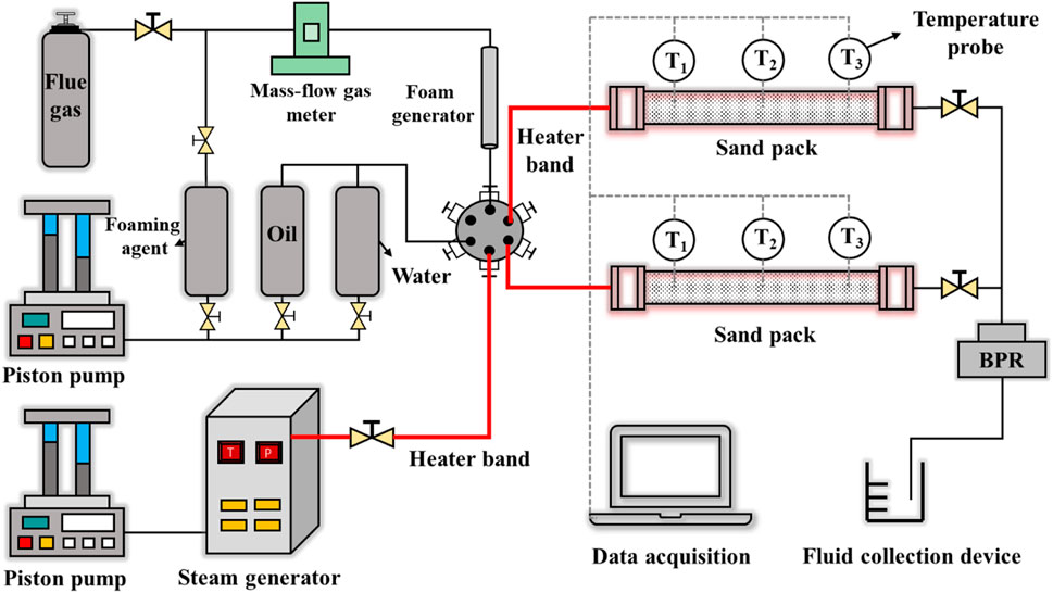
FIGURE 1. The experimental apparatus.
2.2 Experimental procedures
2.2.1 Oil displacement experiment with single-sandpack model
1) In the sandpack model, quartz sand was added and compacted. After being pumped with a vacuum pump for 6 h, water was naturally absorbed to saturation state, and the water absorption volume was the pore volume. Water was injected into the sandpack model at a constant flow rate. When the rate of the produced liquid and the injection rate were equal, the stable flow state was reached. Combined with displacement pressure and geometric parameters of the sandpack model, the effective water flooding permeability was calculated by Darcy formula.
2) The model was wrapped with insulation and placed in a constant temperature environment of 60°C for 2 h. The saturated heavy oil was injected into the model at the rate of 0.1 mL/min, the steam generator was adjusted to 250°C and preheated in advance, and steam or flue gas-assisted steam flooding began to be injected. Relevant parameters of the experiment are shown in Table 1.
3) During the experiment, temperature and pressure data were recorded and liquid and gas production were continuously collected. The surfactants utilized to generate foam were introduced into the model in conjunction with flue gas and steam at the scheduled timing, initiating flue gas foam-assisted steam flooding. When the temperature of each temperature measuring point does not change significantly, the oil displacement ends.
4) At the end of the experiment, oil sands at different locations were sampled, the initial and post-washing weights were weighed, the remaining oil content under different displacement modes was calculated, and the mechanism of corresponding enhanced oil recovery was analyzed.
5) The experimental data were sorted out, the gas retention effect was evaluated, and the action law of flue gas/foam on heat transfer, oil recovery and gas storage during steam oil displacement was explored.
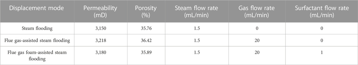
TABLE 1. Relevant parameters of oil displacement experiment with sandpack model.
2.2.2 Parallel oil displacement experiment with dual-sandpack model
1) The two sandpacks were taken and air-dried at 60°C for 4 h, then weighed and placed in a sandpack holder. Water was injected into the sandpack at the rate of 0.5 mL/min. The permeability was calculated when the flow rate was stable, and the wet weight was weighed to obtain the porosity. The sandpack was placed in an incubator and saturated with heavy oil at the rate of 0.1 mL/min. The saturation was completed when water was no longer seen at the outlet. The initial oil saturation of each sandpack was calculated.
2) The two sandpacks with large permeability differences were put into the clamp, and then the oil displacement experiment was started. The steam generator was set at 250°C and the steam flow rate was 2 mL/min. The ratio of permeability between the two sandpacks was 3. High permeability sandpacks were filled with 80–120 mesh quartz sand, while low permeability sandpacks were filled with 100–120 mesh quartz sand. Relevant parameters of the experiment are shown in Table 2.
3) During the experiment, liquid production was continuously collected. When the water content exceeded 95% or the temperature at each temperature measurement point did not change significantly, the oil displacement ended.
4) The oil production rate and oil displacement efficiency of high and low permeability sandpacks were measured respectively, and the influence of permeability difference was analyzed, including the law of foam blocking of hyperpermeability channel, the law of gas channeling in different sandpacks, etc., to reveal the mechanism of interlayer heterogeneity on the degree of steam displacement oil recovery.
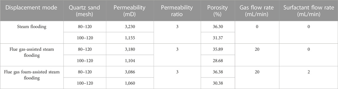
TABLE 2. Experimental parameters of parallel sandpack flooding.
3 Results and discussion
3.1 Oil displacement experiment with single sankpack model
3.1.1 Thermal transfer effect
In this section, surfactant in the flue gas foam-assisted steam flooding was continuously introduced alongside steam and flue gas injection at the beginning of the displacement process. The temperature curves of temperature measurement points at different positions over time are shown in Figure 2. The temperature of all parts of the sand pack increases with time in all 3 sets of experiments, and the farther away from the injection port, the lower the rate of warming as well as the final equilibrium temperature. The temperature difference between the front and end of the flue gas-assisted steam flooding is the smallest, and the final steam heat loss is the largest, while the opposite is true for the flue gas foam-assisted steam flooding.
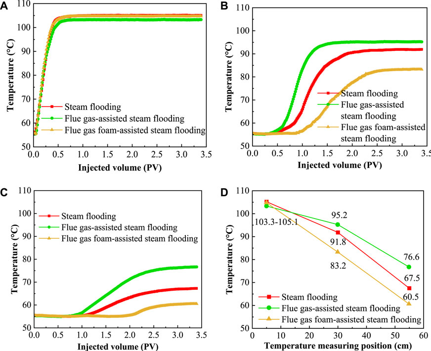
FIGURE 2. Temperature changes in different parts ((A) Temperature change at the front; (B) Temperature change in the middle; (C) Temperature change at the end; (D) Heat equilibrium temperature).
When the steam just enters the inlet, it carries the most heat. At this time, the steam has a high dryness and is a pure gaseous fluid. The temperature measurement point immediately senses the temperature change, and the temperature rises rapidly with a high slope of the curve. The heat transfer of sand and fluid in the steam and model is rapid, and the temperature peaks quickly. Due to the limitation of saturated steam pressure and superheat, the inlet temperature does not change subsequently, and the curve is almost horizontal. At this time, the laws obtained by different displacement modes are consistent, and the steady-state temperature is very close. Because the amount of fluid entering the model is too small, its properties have little influence on heat transfer, and the influence of the temperature gradient is dominant.
The difference of different displacement modes is reflected in the temperature curve in the middle part of the model. There is resistance to steam flow in the model, and it takes a certain time for the steam front to reach the middle part of the model. The curve rarely rises before 0.42 PV, and it begins to rise slowly after the steam heat is sensed. The time for the temperature to rise to the steady state is significantly longer than that in the inlet section, and the stable temperature is also lower, because the steam keeps convective heat transfer with the surrounding medium during the flow process. At the same time, the thermal radiation also plays the role of heat dissipation, resulting in the decrease of heat flux along the flow direction, and the heat transferred to the rear is also reduced. At this point, the maximum temperature of the model is less than 100°C, which means that steam cannot continue to maintain the form of gas phase, but liquefied into hot water. The change of steam phase state will cause the change of flow resistance, heat transfer coefficient and other parameters. As can be seen from Figure 2, the flue gas-assisted steam flooding first reaches the steady state. Due to the low gas viscosity and low flow resistance in the fluid, the flue gas-assisted steam flooding first diffused to the steam front, followed by steam flooding, and flue gas foam-assisted steam flooding. It is not difficult to see that flue gas can increase the speed of steam heat transfer, and the retention of foam in the formation leads to the slowing down of heat propagation rate, which plays a role in regulating fluidity.
As the steam continues to penetrate into the model, the heat loss increases along the process, and the steady-state temperature is about 75°C when displacement mode is flue gas-assisted steam flooding, and even only about 60°C when displacement mode is the flue gas foam-assisted steam flooding. The change rule of the curve is similar to that of the former, but the difference is that the time for the temperature to reach stability is further extended, the slope of the curve is significantly slowed down, and the thermal equilibrium temperature is about 45% lower than that of the inlet section. It is worth noting that in flue gas foam-assisted steam flooding, the temperature in the outlet section tends to rise after about 1.67 PV of the experiment. Compared with the two other displacement modes, the heat transfer rate is the slowest, because the foam blocks the high permeability channel of the model, forcing the subsequent steam to open up a new flow space. From a small scale, the steam main line generates diverts, the number of tributaries increases, and the heat and flow are dispersed to other areas (Bi and Tang, 2013; He and Xie, 2015). However, the power of each tributary is insufficient, and the heat transfer rate is slow on the macro level, which verifies the role of foam in adjusting liquid production profile from the side.
3.1.2 The dynamics of oil displacement
Figure 3 shows the changes of oil producing rate and recovery factor with injected volume. Under different displacement modes, with the increase of injected PV, the oil production rate shows a sharp rise first, then a rapid decline, and finally tends to be stable, except that the flue gas-foam assisted steam flooding has another increase in oil production rate after the first peak. Among the three displacement modes, the peak value of flue gas-assisted steam flooding is the largest, followed by flue gas-foam assisted steam flooding, and finally steam flooding (Figure 3A). Therefore, the cumulative oil recovery factor of flue gas-assisted steam flooding is the largest in the first half. When the injected PV number is 1.53, due to the increase of the second oil production rate of flue gas-foam assisted steam flooding, the cumulative oil recovery factor has achieved reverse overshoot, becoming the displacement mode with the highest cumulative oil recovery factor (Figure 3B).
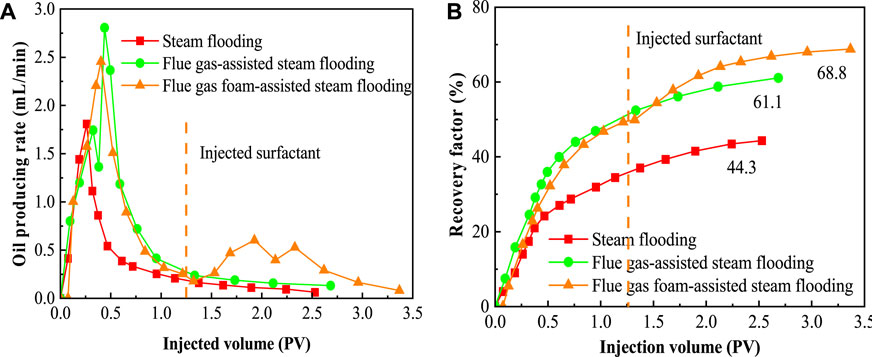
FIGURE 3. The Curve of oil producing rate and recovery factor with injected volume ((A) The curve of oil producing rate; (B) The curve of recovery factor).
Obviously, when the displacing medium just enters the oil-bearing model, the flow velocity is relatively slow due to the influence of flow resistance such as capillary force, fluid friction force and additional force of foam flow deformation. The fluid is in the stage of developing advantageous flow channel, and no channeling occurs in this stage. The formation heavy oil is continuously produced under the driving force, with little water and high oil content, and the oil production rate continues to rise. After a period of time, the fluid at the displacement front is close to the exit position, which means that the dominant channel is formed, and the subsequent fluid percolation tends to flow along this channel, resulting in a decrease in the sweep coefficient. In terms of the different drives, flue gas foam-assisted steam flooding has decent peak production rate and the longest duration of production, which means that the foam flows more slowly, effectively delaying the time of channeling and thus carrying the maximum amount of oil. The change rule of recovery factor is always increasing, and the slope of the curve reflects the change of oil recovery speed. The steeper the curve, the faster the oil recovery speed. Later due to serious injection fluid channeling flow, the heavy oil near the main channel is heated and reduced viscosity, basically all the output, the remaining oil is distributed in the narrow seam network away from the main line, if you do not take sealing channeling measures, continuous injection brings little income, and the recovery factor curve is close to the level.
Figure 4A shows the curve of pressure over time in the process of flue gas foam-assisted steam flooding. As foams continue to enter the model, the blocking effect of foam becomes more and more significant, and the displacement pressure differential curve increases rapidly. After all foams occupy the mainstream channel, a large number of foams can be seen in the produced liquid, as shown in Figure 4B. At this time, the number of foams entering the model should be consistent with the number of output theoretically, and the pressure difference curve fluctuates around a certain equilibrium value. Due to the high viscosity between molecules of heavy oil, a small amount of gas cannot break through and is wrapped in heavy oil to form the state of foam oil and then produced together, indicating that gas is not completely separated from oil and flows, and some of it miscibles into heavy oil molecules, which plays a certain role in improving the fluidity of oil (JPT staff, 2006; Bybee, 2010; Sheikh Mohammad Samiur and Chacko, 2013; Singh, 2014; Karatum et al., 2016). Therefore, it can be inferred that the existence states of flue gas in the model may include such as flue gas locked by foam liquid film, flue gas dissolved in heavy oil and single-phase free gas. Each flue gas plays a different role in enhancing oil recovery. The flue gas in the foam modifies the reservoir structure and increases the sweep range of injected fluid. The flue gas dissolved in the oil reduces the viscosity of the oil, thus increasing its flow capacity; The free flue gas flow velocity block opens up a channel for steam flow behind it, reduces the possibility of steam lingering heat dissipation for a long time, shortens the heat transfer interval between steam and distant heavy oil, and improves the heat transfer efficiency of steam.
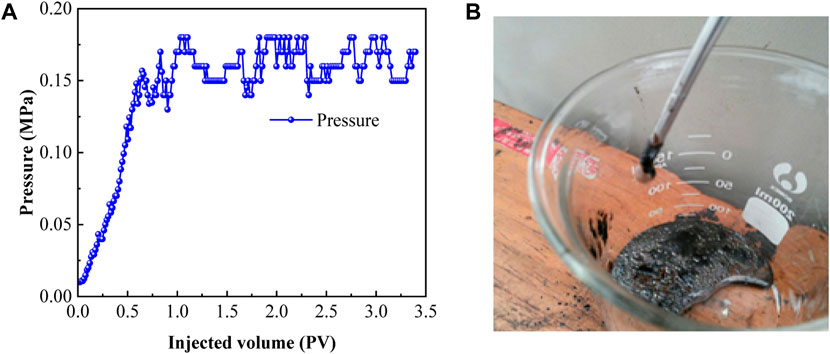
FIGURE 4. The output dynamics during flue gas foam-assisted steam flooding ((A) The pressure curve; (B) The produced oil).
After the experiment, the oil sands at different positions of the model were sampled and analyzed, as shown in Figure 5. As shown below, the oil sands at the entrance were the lightest in color, with the least oil content, and the highest displacement efficiency. From the inlet to the outlet direction, the color of the oil sand deepened, indicating that the remaining oil content is large. Due to the limited heat carried by steam and the serious heat loss during the flow process, the steam waste heat is not enough to promote the flow of the rear heavy oil.
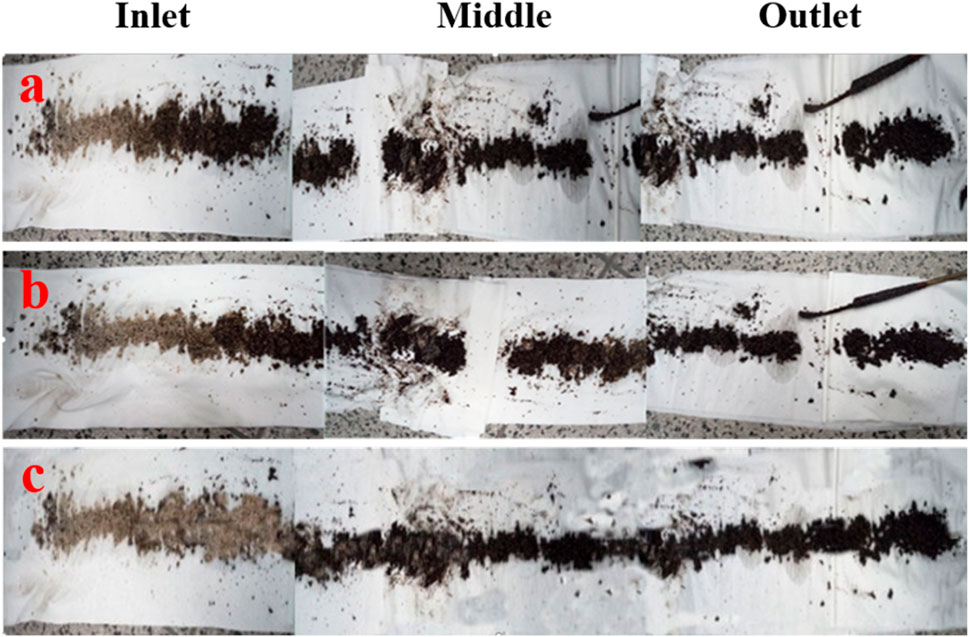
FIGURE 5. The oil sands after displacement ((A) Steam flooding; (B) Flue gas-assisted steam flooding; (C) Flue gas foam-assisted steam flooding).
Figure 6 shows the remaining oil content at each point of the sandpack. The oil content in the inlet section of flue gas foam-assisted steam flooding is the least, less than 5%. Because, in addition to the heating effect of steam, the surfactant in the foam causes emulsification to the heavy oil there, reducing the oil-water interfacial tension, and thus reducing the oil flow resistance. The outlet oil content of flue gas-assisted steam flooding is the lowest, less than 15%, and nitrogen in the gas has strong compression and expansion capacity. When nitrogen collected in the high-pressure area migrates to the low-pressure area, the volume greatly increases to release elastic energy and replenish the energy in the formation deficit, and the formation heavy oil also expands and flows accordingly. The proportion of CO2 in flue gas is relatively small, but its effect on enhancing oil recovery cannot be ignored. CO2 can be miscible with oil to form a miscible phase and reduce the viscosity of heavy oil. In addition, studies have shown that CO2 can also extract light components in heavy oil and play a role in improving quality and reducing viscosity (Yuan et al., 2011; Nguyen et al., 2014; Wei et al., 2018; Sun et al., 2019).
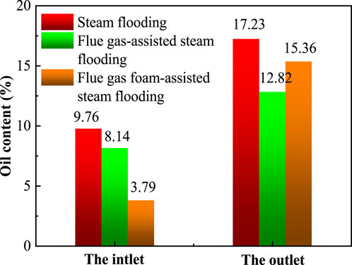
FIGURE 6. The remaining oil distribution at different positions.
3.1.3 Gas retention characteristics
Figure 7 shows the gas production and retention curves of the two displacement modes as the PV number of injected gas increases. As shown in Figure 7A, gas is also produced continuously in the injection process of flue gas-assisted steam flooding and flue gas foam-assisted steam flooding, and the gas production curve presents an overall upward trend. Combined with the retained gas curve (Figure 7B), it is found that the amount of retained gas in the early stage of injection far exceeds the amount of produced gas, so the dominant flow channel is not formed, and the gas does not occur large-scale channeling, but is more locked in the foam and heavy oil in the form of dissolved state. With the extension of time, the displacement phase fluid gradually occupied the pore space of the model and brought out the originally high viscosity heavy oil, which reduced the resistance of subsequent fluid flow, resulting in a rapid increase in gas production rate, corresponding to a rapid increase in gas production. At this time, the blocking effect of foam could no longer effectively inhibit gas channel flow, the amount of gas trapped in the model tended to be saturated, and the slope of the trapped gas curve decreased. By calculation, at the end of the experiment, the gas retention under the flue gas-assisted steam flooding is 238 mL, and the gas retention under the flue gas foam-assisted steam flooding is 389 mL, which again confirms the ability of foam sealing and strengthening gas storage.
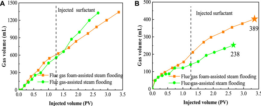
FIGURE 7. Gas production and during storage displacement ((A) Gas production during displacement; (B) Gas retention during displacement).
3.2 Parallel oil displacement experiment with dual-sandpack model
To further study the effect of formation heterogeneity on oil recovery and residual oil distribution during displacement, the crude oil production dynamic rate and the distribution characteristics of remaining oil were analyzed. The surfactant was always injected at the beginning of flue gas foam-assisted steam flooding.
3.2.1 Recovery factor and remaining oil distribution
The relationship between high and low permeability sandpack displacement efficiency and injection volume is shown in Figure 8. No matter the sandpack permeability difference and the type of displacement method, the change law of oil displacement efficiency is generally the same, that is, with the increase of injection volume, the oil displacement efficiency increases rapidly in the early stage, then the rate slows down, and finally becomes stable. The steam flooding curve is always below the other two curves, and the oil displacement efficiency is the lowest at the same injection volume, which is attributed to the low steam heat utilization rate, resulting in poor oil displacement efficiency. In the flue gas foam-assisted steam flooding, their curves in the high permeability sandpack almost coincide, the difference in oil displacement efficiency is small, close to 7 layers of oil are taken out, showing good oil displacement ability (Figure 8A). In the low permeability sandpack, the advantage of foam becomes obvious, and the oil displacement efficiency at stability is 20%, which is 8% and 12% higher than that of flue gas-assisted steam flooding and steam flooding, respectively (Figure 8B).
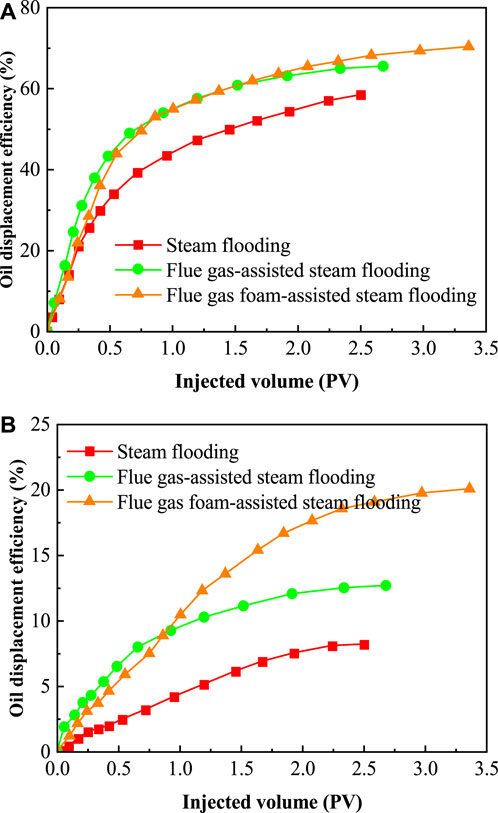
FIGURE 8. Oil displacement efficiency ((A) High permeability sandpack; (B) Low permeability sandpack).
Figure 9 illustrates the remaining oil content at different positions of the sandpack under different displacement modes and permeability. The oil content of the sandpack is in opposition to the oil displacement rate. The higher the oil displacement efficiency, the lower the oil content of the area, and the oil content of the front end is generally about 10% lower than that of the back end. Consistent with the conclusion drawn above, the steam displacement efficiency is the lowest, and the oil content is the highest at the front and back of the sandpack. The flue gas foam-assisted steam flooding has the best oil displacement effect, and the oil content in the front and back end of the high permeability sandpack is only 6.9% and 10.3%. According to past experience, this residual oil may be located in the blind end pores or “dead oil zone” where the displacement phase does not flow, which is technically unrecoverable. In general, flue gas foam-assisted steam flooding can maximize the use of sandpack heavy oil, and its various EOR mechanisms promote each other, effectively solving several difficulties such as steam channeling, serious heat loss, and heavy oil flow resistance (Butler, 2004; Yee and Stroich, 2004; Jianfang et al., 2014).
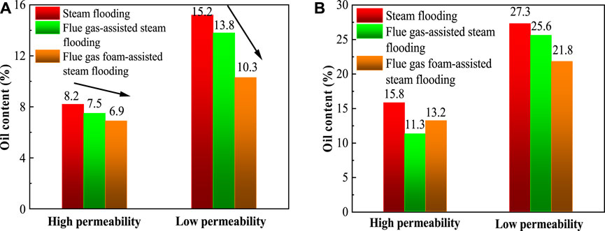
FIGURE 9. Oil content of different parts ((A) Oil content of the front; (B) Oil content of the end).
3.2.2 Gas production characteristics
Figure 10 shows gas production curves under different displacement modes in parallel sandpack. In the high permeability sandpack, the cumulative gas production reached 2076 mL and 2,281 mL, respectively. There is no inflection point throughout the line, and it has been in a monotonically increasing state, indicating that the gas output in the high-permeability sandpack is very rapid, and correspondingly the amount of ground gas retained in the sandpack is small, and the ground capacity of gas storage is low. In low permeability sandpack, gas flow is inhibited to some extent due to narrow gas flow channels and poor connectivity between pores. The cumulative gas production of flue gas-assisted steam flooding and flue gas foam-assisted steam flooding decreased significantly compared with hyperosmotic conditions, and the curve law was still monotonically increasing, with smaller derivative value and smaller increase rate. The final gas output was 428 mL and 1,189 mL, respectively. The addition of foam, which has the ability of sealing the high permeability formation and adjusting the vapor absorption profile, reduces the gas flow in the high permeability sandpack and increases the gas flow in the low permeability sandpack, and makes the gas distribution more uniform (Lyu et al., 2021; Li S et al., 2023).
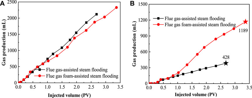
FIGURE 10. Gas production of different permeability sandpack ((A) Gas production of high permeability sandpack; (B) Gas production of low permeability sandpack).
4 Conclusion
1) Flue gas can effectively inhibit steam heat dissipation, while foam, although less effective in inhibiting steam heat dissipation, can effectively block the steam channel and prolong the thermal action time. In the flue gas-assisted steam flooding, the temperature in the middle and end of the model is increased by 4.4°C and 9.1°C respectively compared with steam flooding, effectively retaining steam waste heat, and the final recovery efficiency is increased to 58.3%. Due to longer thermal action time, the final recovery efficiency of flue gas foam-assisted steam flooding is increased to 68.7%.
2) The sealing effect of the foam is effective in increasing gas retention. During flue gas-assisted steam flooding displacement, the volume of gas trapped in the model is very limited due to rapid channeling. In the case of flue gas foam-assisted steam flooding, the injection pressure curve rose rapidly in a short time, and a large amount of foam accumulated in the pore channels between the sand grains, resulting in the blocking effect, inhibiting the rapid production of gas, and making the final retention volume reach 389 mL, which has an obvious sealing effect.
3) Foam as an additive and its excellent anatomical plugging ability can effectively improve the formation non-homogeneity and enhance the recovery of heavy oil from low-permeability formations. In the oil displacement experiment, the final recovery of flue gas foam-assisted steam flooding in the high permeability sandpack was increased by 4.8% compared with that of flue gas-assisted steam flooding, while it was increased by 7.4% in the low permeability sandpack. The reason for this is that the foam improves the problem of steam channeling and increases the efficiency of the use of steam heat.
Data availability statement
The original contributions presented in the study are included in the article/Supplementary material, further inquiries can be directed to the corresponding author.
Author contributions
QC: Conceptualization, Data curation, Methodology, Writing–original draft. TW: Formal Analysis, Validation, Writing–review and editing. GW: Data curation, Validation, Writing–original draft. JY: Formal Analysis, Investigation, Writing–original draft. KT: Methodology, Project administration, Writing–original draft. AC: Conceptualization, Writing–review and editing.
Funding
The author(s) declare financial support was received for the research, authorship, and/or publication of this article. This study was supported and funded by the National Natural Science Foundation of China (Grant No. U20B6003) and China Petroleum & Chemical Corporation (SINOPEC) Research Project (Project P21037-4).
Conflict of interest
Authors QC, TW, GW, JY, and KT were employed by Exploration and Development Research Institute of Shengli Oilfield, Sinopec.
The remaining authors declare that the research was conducted in the absence of any commercial or financial relationships that could be construed as a potential conflict of interest.
The authors declare that this study received funding from China Petroleum & Chemical Corporation (SINOPEC). The funder had the following involvement in the study: design, collection, analysis, interpretation of data, the writing of this article.
Publisher’s note
All claims expressed in this article are solely those of the authors and do not necessarily represent those of their affiliated organizations, or those of the publisher, the editors and the reviewers. Any product that may be evaluated in this article, or claim that may be made by its manufacturer, is not guaranteed or endorsed by the publisher.
References
Alomair, O. A., and Alajmi, A. F. (2022). A novel experimental nanofluid-assisted steam flooding (NASF) approach for enhanced heavy oil recovery. Fuel 313, 122691. doi:10.1016/j.fuel.2021.122691
Bi, C., and Tang, G. (2013). Effective thermal conductivity of the solid backbone of aerogel. Int. J. Heat. Mass Transf. 64, 452–456. doi:10.1016/j.ijheatmasstransfer.2013.04.053
Butler, R. M. (2004). The behaviour of non-condensible gas in SAGD-a rationalization. J. Can. Pet. Technol. 43. doi:10.2118/04-01-02
Bybee, K. (2010). Cryogenic piping reduces the effect of LNG transfer terminals on local communities. J. Pet. Technol. 62, 67–69. doi:10.2118/0410-0067-jpt
Castanier, L., and Brigham, W. (2003). Upgrading of crude oil via in situ combustion. J. Pet. Sci. Eng. 39, 125–136. doi:10.1016/s0920-4105(03)00044-5
Deng, H. (2021). Laboratory evaluation of new foam agent for profile control and flooding integrated high-temperature flue gas drive. Spec. Oil Gas. Reserv. 28, 105–112. doi:10.3969/j.issn.1006-6535.2021.06.014
He, T., Li, Y., Zhao, J., Gao, H., Wei, B., Sun, L., et al. (2023). Dynamic features of nonaqueous foam in fracture systems. Energy & Fuels 37, 5048–5058. doi:10.1021/acs.energyfuels.3c00040
He, Y., and Xie, T. (2015). Advances of thermal conductivity models of nanoscale silica aerogel insulation material. Appl. Therm. Eng. 81, 28–50. doi:10.1016/j.applthermaleng.2015.02.013
Jianfang, S., Wu, G., Liu, C., and Li, W. (2014). “Mechanism and application of improving heavy oil recovery greatly by solvent and foam assisted steam flooding,” in Proceedings of International Petroleum Technology Conference, Doha, Qatar, 19-22 January 2014.
Jpt Staff (2006). Technology update: new options, improved economics from aerogel insulation. J. Pet. Technol. 58, 24. doi:10.2118/0606-0024-jpt
Karatum, O., Steiner, S. A., Griffin, J. S., Shi, W., and Plata, D. L. (2016). Flexible, mechanically durable aerogel composites for oil capture and recovery. ACS Appl. Mater. Interfaces 8, 215–224. doi:10.1021/acsami.5b08439
Li, B., Li, B., Zang, Y., Zhu, D., Li, Z., and Ruan, L. (2023). Experimental study of the distillation mechanism during coinjection of flue gas and steam for heavy oil development. Sep. Purif. Technol. 324, 124553. doi:10.1016/j.seppur.2023.124553
Li, S., Wang, P., Wang, Z., Cheng, H., and Zhang, K. (2023). Strategy to enhance geological CO2 storage capacity in saline aquifer. Geophys. Res. Lett. 50, 101431. doi:10.1029/2022gl101431
Li, S., Yu, T., Li, Z., and Zhang, K. (2019). Experimental investigation of nitrogen-assisted SAGD in heavy-oil reservoirs: a two-dimensional visual analysis. Fuel 257, 116013. doi:10.1016/j.fuel.2019.116013
Li, Y. (2023). Editorial: the challenge and opportunity of CCUS in the development of unconventional resource. Front. Energy Res. 11, 1153929. doi:10.3389/fenrg.2023.1153929
Li, Y., He, T., Zhao, J., Lin, X., Sun, L., Wei, B., et al. (2023b). Gas-liquid surface characterization and liquid film thinning of Non-Aqueous foam. J. Mol. Liq. 388, 122780. doi:10.1016/j.molliq.2023.122780
Li, Y., Jia, H., Pu, W., Wei, B., Wang, S., and Yuan, N. (2023a). Investigation of feasibility of alkali–cosolvent flooding in heavy oil reservoirs. Pet. Sci. 20, 1608–1619. doi:10.1016/j.petsci.2022.12.001
Li, Y., Zhang, S., Luo, C., Zhao, S., Wei, B., and Pu, W. (2022). An experimental investigation in the formation damage mechanism of deposited coke in in-situ combustion process using nuclear magnetic resonance. Fuel 313, 122703. doi:10.1016/j.fuel.2021.122703
Li, Z., Lu, T., Tao, L., Li, B., Zhang, J., and Li, J. (2011). CO2 and viscosity breaker assisted steam huff and puff technology for horizontal wells in a super-heavy oil reservoir. Pet. Explor. Dev. 38, 600–605. doi:10.1016/s1876-3804(11)60059-1
Li, Z., Xu, Y., Lu, T., Yang, J., Wang, H., and Shang, Z. (2020). Research on the mechanism of enhanced deep steam heat transfer by non-condensable gases. Spec. Oil Gas. Reserv. 27, 113–117. doi:10.3969/j.issn.1006-6535.2020.04.017
Lu, T., Ban, X., Li, Z., Gao, Y., Guo, E., Yang, J., et al. (2021). Mechanism of flue gas-assisted SAGD steam chamber expansion. Acta Pet. Sin. 42, 1072–1080. doi:10.7623/syxb202108008
Lyu, X., Voskov, D., and Rossen, W. R. (2021). Numerical investigations of foam-assisted CO2 storage in saline aquifers. Int. J. Greenh. Gas. Control 108, 103314. doi:10.1016/j.ijggc.2021.103314
Nguyen, P., Fadaei, H., and Sinton, D. (2014). Pore-scale assessment of nanoparticle-stabilized CO2 foam for enhanced oil recovery. Energy fuels. 28, 6221–6227. doi:10.1021/ef5011995
Pang, Z., Liu, H., and Zhu, L. (2015). A laboratory study of enhancing heavy oil recovery with steam flooding by adding nitrogen foams. J. Pet. Sci. Eng. 128, 184–193. doi:10.1016/j.petrol.2015.02.020
Sheikh Mohammad Samiur, R., and Chacko, S. (2013). Improved paraffin-deposition-profile estimation in hydrocarbon pipelines and effective mitigation review. Oil Gas Facil. 2, 78–85. doi:10.2118/165933-pa
Singh, A. (2014). “Utilising aerogel in effective oil spill cleanup and recovery,” in Proceedings of Offshore Technology Conference-Asia, Kuala Lumpur, Malaysia, 25-28 March 2014.
Sun, H., Wang, Z., Sun, Y., Wu, G., Sun, B., and Sha, Y. (2020). Laboratory evaluation of an efficient low interfacial tension foaming agent for enhanced oil recovery in high temperature flue-gas foam flooding. J. Pet. Sci. Eng. 195, 107580. doi:10.1016/j.petrol.2020.107580
Sun, L., Bai, B., Wei, B., Pu, W., Wei, P., Li, D., et al. (2019). Recent advances of surfactant-stabilized N2/CO2 foams in enhanced oil recovery. Fuel 241, 83–93. doi:10.1016/j.fuel.2018.12.016
Sun, Y. (2016). Study on molecular design and application performance of surfactant multi compound low tension foam oil displacement system. Jinan: Shandong University.
Turta, A., Chattopadhyay, S., Bhattacharya, R., Condrachi, A., and Hanson, W. (2007). Current status of commercial in situ combustion projects worldwide. J. Can. Pet. Technol. 46. doi:10.2118/07-11-ge
Wang, C., Liu, H., Pang, Z., Wang, J., Chen, C., Wang, C., et al. (2015). Enhance oil recovery for steam flooding: low-temperature oxidative decomposition of heavy oil with air injection. Energy fuels. 29, 6242–6249. doi:10.1021/acs.energyfuels.5b01330
Wang, D., Zhou, N., and Mou, K. (2008). Current status and development trends of heavy oil thermal recovery technology. West-China Explor. Eng. 12, 129–131.
Wang, Z., Li, S., Jin, Z., Li, Z., Liu, Q., and Zhang, K. (2023). Oil and gas pathway to net-zero: review and outlook. Energy Strateg. Rev. 45, 101048. doi:10.1016/j.esr.2022.101048
Wang, Z., Li, S., and Li, Z. (2022). A novel strategy to reduce carbon emissions of heavy oil thermal recovery: condensation heat transfer performance of flue gas-assisted steam flooding. Appl. Therm. Eng. 205, 118076. doi:10.1016/j.applthermaleng.2022.118076
Wei, B., Li, Q., Wang, Y., Gao, K., Pu, W., and Sun, L. (2018). “An experimental study of enhanced oil recovery EOR using a green nano-suspension,” in Proceedings of SPE Improved Oil Recovery Conference, Tulsa, Oklahoma, USA, 14-18 April 2018.
Wei, S., Duan, Y., Wei, M., Ren, K., Lu, C., Zhan, J., et al. (2022). Experimental study on the effect of different distributed interlayer on SAGD performance. J. Pet. Sci. Eng. 209, 109827. doi:10.1016/j.petrol.2021.109827
Xia, T., and Greaves, M. (2000). “Upgrading Athabasca tar sand using toe-to-heel air injection,” in Proceedings of SPE/CIM International Conference on Horizontal Well Technology, Calgary, Alberta, Canada, 6-8 November 2000.
Xu, Z., Li, Z., Jing, A., Meng, F., Dang, F., and Lu, T. (2019). Synthesis of magnetic graphene oxide (MGO) and auxiliary microwaves to enhance oil recovery. Energy fuels. 33, 9585–9595. doi:10.1021/acs.energyfuels.9b01841
Yang, J., Li, X., Chen, Z., Tian, J., Liu, X., and Wu, K. (2016). Combined steam–air flooding studies: experiments, numerical simulation, and field test in the qi-40 block. Energy fuels. 30, 2060–2065. doi:10.1021/acs.energyfuels.5b02850
Yee, C., and Stroich, A. (2004). Flue gas injection into a mature SAGD steam chamber at the Dover Project (Formerly UTF). J. Can. Pet. Technol. 43. doi:10.2118/04-01-06
Yu, L. (2001). The distribution of heavy oil resources in the world and the current status and prospects of their extraction technologies. Spec. Oil Gas. Reserv. 8, 98–103.
Yuan, J., Chen, J., Pierce, G., Wiwchar, B., Golbeck, H., Wang, X., et al. (2011). Noncondensable gas distribution in SAGD chambers. J. Can. Pet. Technol. 50, 11–20. doi:10.2118/137269-pa
Zhang, X., Liu, Q., and Che, H. (2013). Parameters determination during in situ combustion of Liaohe heavy oil. Energy fuels. 27, 3416–3426. doi:10.1021/ef400095b
Zhang, Y., Zhang, L., Chen, B., Li, H., Wang, Y., and Ren, S. (2014). Performance evaluation and experimental method research of high-temperature and high-pressure CO2 foam. J. Chem. Eng. Chin. Univ. 28, 535–541. doi:10.3969/j.issn.1003-9015.2014.03.016
Keywords: flue gas foam, heavy oil, enhanced oil recovery, heat loss, gas storage
Citation: Cao Q, Wei T, Wu G, Yu J, Tian K and Cao A (2023) Experimental study on flue gas foam-assisted steam flooding: investigating characteristics of enhanced oil recovery and gas storage. Front. Energy Res. 11:1328292. doi: 10.3389/fenrg.2023.1328292
Received: 26 October 2023; Accepted: 10 November 2023;
Published: 23 November 2023.
Edited by:
Yibo Li, Southwest Petroleum University, ChinaReviewed by:
Hailong Chen, Southwest Petroleum University, ChinaZhengxiao Xu, Changzhou University, China
Copyright © 2023 Cao, Wei, Wu, Yu, Tian and Cao. This is an open-access article distributed under the terms of the Creative Commons Attribution License (CC BY). The use, distribution or reproduction in other forums is permitted, provided the original author(s) and the copyright owner(s) are credited and that the original publication in this journal is cited, in accordance with accepted academic practice. No use, distribution or reproduction is permitted which does not comply with these terms.
*Correspondence: Aiqing Cao, caq0000@163.com