Simulated safety analysis of a total loss of feedwater accident in the steam generator of CPR1000 nuclear power plant
 Guanyi Wang
 Chaoying Zheng
 - Nuclear and Radiation Safety Center, Beijing, China
As M310 series units, CPR1000 Nuclear Power Plant in China is also the first batch of demonstration nuclear power plants in China to try out SOP(the state-oriented procedure) accident procedures. The establishment of SOP accident regulations is an important work to mitigate the consequences of radioactive accidents in the design of nuclear power plants, and it is also the embodiment of the defense-in-depth requirements in the implementation of nuclear safety regulations. It can handle superimposed accidents, human errors in program implementation and events not considered in the primary cause sequence. In order to study the efficiency of its upgraded SOP procedure and its ability to deal with severe accidents, the typical primary cause event of severe accidents in nuclear power plants–such as the total loss of feedwater accident of steam generators has been adopted for research. The initial state of the simulation is the full power operation of the nuclear power plant, the simulation process is from the loss of all the water supply accidents to the whole accident processing. A total of 30 simulation experiments were carried out. The temperature and pressure of the key parameters obtained are the average values of 30 simulation experiments. The stability and efficiency of the updated SOP are evaluated by the treatment time of the water supply loss accident and the changes of reactor temperature and pressure after the accident. The results show that the upgraded SOP procedure is more stable and efficient. The upgraded SOP procedure, when dealing with other types of accidents, has improved the treatment of residual heat conduction in the core, increased the efficiency of accident treatment, and enhanced the safety of the reactor. At the same time, based on the weaknesses of the upgraded SOP procedure, constructive suggestions on changing the setting value of the steam generator bypass valve have also been put forward accordingly. Furthermore, it can be concluded from many simulated accidents that this change will win about 5% more of the disposal time for nuclear power plants under accidents, which provides references for the subsequent upgrading of M310 series power plant procedures.
1 Introduction
With the discovery of Nuclear Fission in 1938 (DOE/NE-0088, 2011), scientists considered nuclear energy as an alternative mean to generate power and thus developed nuclear fission reactors. These reactors however, require continuous cooling in order to extract nuclear fission energy as well as to keep nuclear fuel well below its melting point (Zubair et al., 2017). Currently with the advantages of cleanness, environmental protection and low consumption, nuclear power has become the third largest power supply pillar after thermal power and hydropower. Moreover, with the increasing tension of energy supply around the world, the development of nuclear power is bound to be faster and faster. Science and Technology Daily, Beijing, November 1 (Reporter Chen Yu) Wang Shoujun, president of the Chinese Nuclear Society, introduced at the 23rd Pacific Nuclear Energy Conference held on the first that, as of June 2022, the number of nuclear power-generating units in operation in China has reached 53 (Yi, 2022). Since the first nuclear power plant in the world was built and put into operation in 1954, the development of nuclear power has gone through several important stages, which can be divided into the so-called first generation, the second generation and the third generation. It is generally believed that the first generation refers to nuclear power plants developed and constructed before the 1960s, the second generation refers to nuclear power plants developed and constructed after the 1970s, and the third generation is still under development and has not started large-scale construction. Between the second generation and the third generation, there is also a liquid passing reactor type, which can be called the 2.5 generation or “second generation plus”, that is, the improved version of the second generation. In addition, M310 unit can also be considered to be the nuclear power technology unit of “improved version of the second generation” [For example, a filter containment and venting systems was added (Li et al., 2022)], which is designed, manufactured, constructed and operated independently in China (Liu, 2022). Most of the nuclear power plants in operation use M310 series units, which needs to be strengthened in terms of accident treatment capacity compared with the third-generation nuclear power units, although the overall technology of such units is relatively mature. In the past, most of the accident procedures used by units were EOP-type (According to the occurrence of the accident to implement the appropriate procedures), which has the advantages of strong pertinence and fast execution. The basic principle of EOP(procedure is that after an initial event occurs in the main control room, the reactor operator, the secondary loop operator, and the coordinator simultaneously execute their respective accident procedures. They diagnose according to the guidelines of the diagnostic procedures and collect the information provided by the control room, judge the type of accident currently occurring in the unit, and then enter the following accident procedures to take corresponding actions to deal with the accident:1) Fault and design standard accident procedures; 2) Procedures for exceeding-design baseline accidents; 3) Emergency operation procedures for extreme operating conditions. However, there are also obvious limitations, that is, only a specific single accident can be handled, but not the superimposed accident caused by expected equipment failure or human error. For this reason, in recent years, the SOP procedure (the corresponding regulations are implemented according to the unit status of the nuclear power plant) that is more comprehensive and systematic has been adopted to replace the EOP procedure in the old generation of domestic units (Wu et al., 2011). The possible physical state of the reactor caused by an infinite combination of events (equipment failure or superposition with human failure) is limited, and the physical state of the reactor can be identified by monitoring several representative parameters. Periodic diagnosis of physical conditions to achieve overall safety objectives, definition of priority levels, and corrective control actions of state functions constitute the principles of SOP incident handling. Compared to SOP, EOP has the following advantages:
(1) The highly systematization and formatting of programs enable a limited number of programs to be used to cover possible accident conditions;
(2) Through regular diagnosis of physical state and annular structure, operators can always verify the effectiveness of the operating strategy being implemented. Even if the accident development tends to be complex (human error, superimposed fault), they can also find the appropriate operating strategy again, which is characterized by “error tolerance” and “self-correction";
(3) Unavailable or failed systems can be replaced or restored;
(4) The redundancy of function target control means makes the operator always have an available solution to be implemented, thus improving the operability and timeliness of the program;
(5) The accident diagnosis logic can be executed by any authorized person (operator, machine leader, shift supervisor, safety worker) at any time. In fact, the reinforcement of personnel redundancy is consistent with the principle of personnel redundancy in the setting of production organization
The upgraded SOP protocol avoids the shortcomings of the EOP protocol, is highly systematic and formatted, can be “Error tolerant” and “Self-correcting”, and is more operable and timely. The ability to deal with a combination of unexpected equipment failures or human failures (errors) has been greatly enhanced.
At present, most of the nuclear power plants operating in China are equipped with units using M310 technology, among which CPR1000 Nuclear Power Plant is a typical M310 series nuclear power plant (Jiao et al., 2021). The internal events of nuclear power plant are complex and include equipment maintenance, equipment damage, etc. These events will affect the probability of the current risk level of the system as well as the reliability of the equipment parameter values so such kind of events will serve as an important basis for systematic analysis and calculation (Zubair et al., 2011). Indeed, there are relatively strict regulations and procedures in the design, construction and operation of the overall nuclear power plant. In addition, after the Three Mile Island accident, relevant improvement measures have also been implemented. However, once a serious accident occurs, it will do great harm to the units and the environment. Therefore, in order to avoid serious accidents as much as possible, it is necessary to have a faster and more accurate accident treatment mechanism and system at the beginning of the accident, so as to prevent or delay the accident from developing into a serious accident. In fact, this also puts forward higher requirements for accident procedures and operators.
Based on the deficiencies of the above research, this paper uses a full scope simulator to simulate the steam generator loss of feedwater accident. Under the condition that there is no operator intervention, the system operation parameters under the non-upgraded SOP procedure and upgraded SOP procedure are recorded to obtain the numerical changes of key unit safety parameters, thereby verifying the effect of the upgraded procedure. Besides, the improvement method for the existing upgraded SOP procedure is proposed to deal with the accident and obtain relevant parameters, which will be compared with the parameters under the original procedure to verify the effect of the improved SOP procedure.
2 Simulated equipment and model
2.1 The methodology
The complete loss of feedwater accident of steam generator is simulated according to the actual situation of the power plant. At the same time, the SOP procedures before and after the upgrade are used to deal with the feedwater accident of steam generator loss. Through the comparative simulations, the technicians can analyze the changes of main parameters and unit status after the nuclear power plant accident is handled to determine the advantages of the upgraded SOP procedure. In addition, according to the problems found in the simulation, the staff can put forward corresponding suggestions to better improve the SOP procedures.
2.2 Full scope simulator
Figure 1 shows the hardware system diagram of the full scope simulator of the nuclear power plant. Generally, the full scope simulator is composed of front-end monitoring and display equipment in the control room of the simulated nuclear power plant, background power plant equipment status and operation parameter simulation calculation process model, background power plant digital control system simulation model, teaching control system, computer cluster and other components and equipment. The establishment of its model mainly depends on two programs, namely, Relap5 and MELCOR2.1. Among them, RELAP5 program is mainly aimed at the modeling of design basis conditions, while MELCOR2.1 is aimed at the modeling of severe accident conditions. Meanwhile, this simulator can continuously simulate the operation of the reference power station in real time, including normal operation steady and transient conditions, abnormal conditions and accident conditions. Furthermore, through continuous, real-time and iterative numerical calculation of the dynamic simulation model of the reference power plant, the simulator displays the equipment status and operating parameters under various operating conditions of the nuclear power plant on various display or indication devices in the control room of the simulator; Therefore, through fault simulation and receiving manual operation signals from the analog control equipment, the simulator can predict various operating parameters of the nuclear power plant under the conditions of manual intervention and equipment status changes in the nuclear power plant operation transient and accident conditions, thus providing a simulation environment similar to the actual control room of the nuclear power plant and achieving the purpose of practical research. In general, this simulator is particularly suitable for emergency drill, design verification, operation analysis and other technical research and analysis.
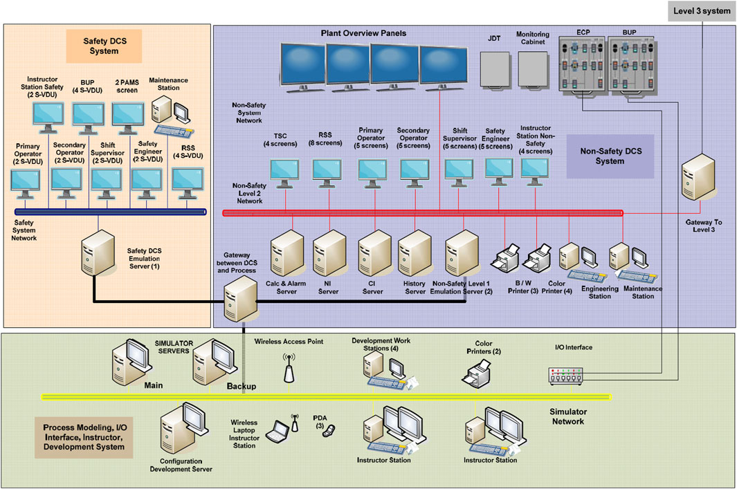
Figure 1. Hardware system diagram of full scope simulator of nuclear power plant.
2.3 Simulation software platform
3KEYMaster is a fully integrated simulation development software environment, which is the first simulation software platform developed based on Windows operating system. At the same time, 3KEYMaster has an open structure and is completely object-oriented. On the other hand, its good graphical human-computer interface provides a convenient and efficient use for the operators. The establishment of its model mainly depends RELAP5-3D. The simulation software platform is 3KEYMaster. This study mainly applies these two software.
2.3.1 Thermal hydraulic model
The simulation platform software is the core technology and basic technology platform of the simulator. At the same time, the 3KEYRELAP5-RT package was used to develop the thermal hydraulic model of the full scope simulator of CPR1000 Nuclear Power Plant, which will simulate the entire reactor vessel, including the reactor pressure vessel, reactor core and pressurizer. In addition, each loop has three separate circulation loops of SG (steam generator) and RCP (main circulation pump), while the secondary side of the steam generator directly includes the main steam pipe section of the main steam check valve and steam relief valve, as well as the section between the pressurizer relief line and the PRT. Also included Reactor protection system (RPS). Reactor protection system (RPS) compares the operating parameters with set points and initiates the scram to protect the core by inserting shutdown control rods. It also works in case of external hazard. RPS consists of sensors, analog/digital protection logic, actuation circuit, and circuit breakers (Khalil Ur et al., 2013). The specific thermal hydraulic model is shown in Figures 2–4. The single model is used for relevant calculation in the processes from full power operation to the operation with coolant capacity reduced. Therefore, the model can accurately predict the conditions consistent with the accident safety analysis in the final safety analysis report (FSAR) of the unit. The boundary conditions of the simulation parameters in this paper are: the total flow of the loop is 23,790 m3/h, and the pressure drop in the middle cooling section, hot section and transition section of the main pipe is 0.13bar, 0.12bar and 0.28bar respectively. Hydraulic components and their functions used for pressure vessels are shown in Table 1, while hydraulic components and their functions used for main pipelines, main pumps and regulators are shown in Table 2.
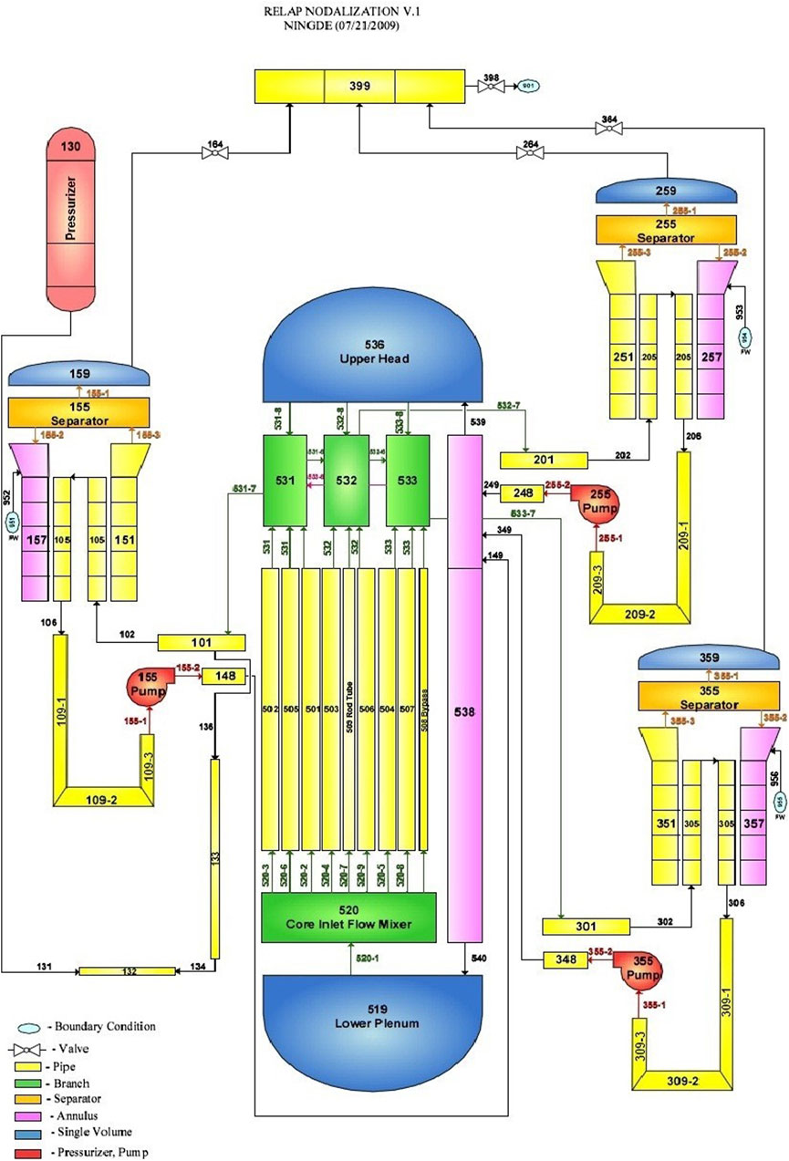
Figure 2. Schematic diagram of node division of thermal hydraulic model.
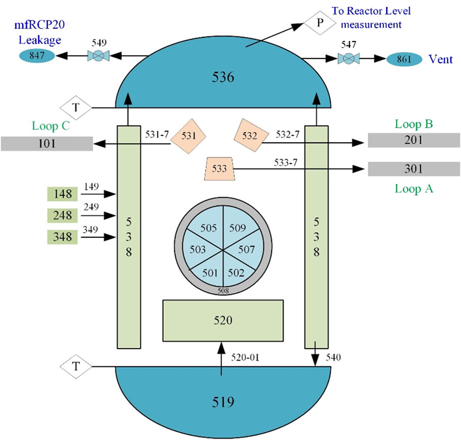
Figure 3. Reactor pressure vessel.
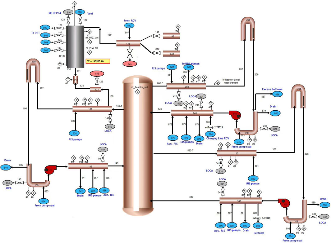
Figure 4. Primary main loop.
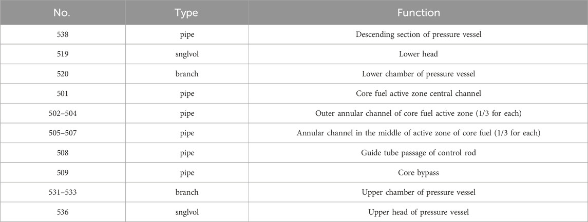
Table 1. Hydraulic components and functions of pressure vessels.
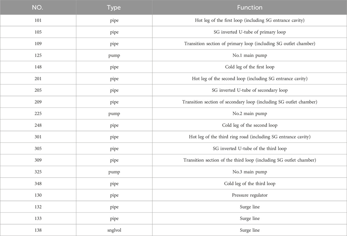
Table 2. Number and function of hydraulic parts used in main pipeline, main pump and pressurizer.
2.3.2 Neutron model and Relap5 model
The RELAP5R/T program embedded with the NESTLE program package was employed in the full scope simulator (developed by North Carolina State University (NCSU), the node eigenvalue, core steady state, and transient linear solver) to develop the core dynamics model of the full scope simulator for CPR1000 Nuclear Power Unit. In fact, it is a real two energy group, three-dimensional reactor neutron dynamics calculation program, which can be used to calculate the neutron flux and power of each segment in each time step. In the time step of each neutron diffusion calculation, the program is used to calculate the diffusion of related segments on the basis of the assumption that the thermal hydraulic conditions are constant. The diffusion equation is solved by nonlinear iteration in the form of all two groups using the nodal expansion method. At the same time, control rods can be simulated individually or in groups, or partially or completely inserted.
NESTLE program is developed based on the basic equations of dependent neutron diffusion theory related to the space-time. Therefore, it is an inherent fully dynamic model of three-dimension and multi-node that can calculate the neutron flux and power of each node in each time step. Among them, the model in RELAP5 is responsible for calculating the thermodynamic and hydraulic parameters required for the calculation of the neutron dynamics module. While the calculation model of neutron dynamics module is responsible for calculating the fission power and fission product decay power on the basic segment required for RELAP5 calculation. Moreover, the neutron dynamics module provides its output by performing nodal diffusion calculations and assuming that the thermal hydraulic conditions are constant in a single time step. At the same time, NESTLE can obtain the most accurate simulated core response by using the reload data of the actual power plant core and operating with RELAP5. Figure 5 shows the composition and structure of the neutron dynamics module. Similar to the thermal hydraulic structure diagram, this module is composed of NESTLE programming and specific input model of CPR1000 Nuclear Power Plant.
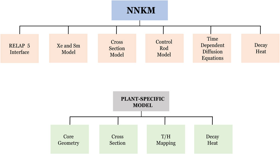
Figure 5. Block diagram of submodule.
2.4 SOP accident procedure
2.4.1 Principle of SOP procedure
The EOP accident procedure is handled in such a way that when an accident occurs, the reactor operator, the secondary circuit operator and the coordinator simultaneously implement their own accident procedures. At the same time, according to the guidance of the diagnostic procedure, they collected the information provided by the control room and made relevant diagnosis to judge the type of accident currently occurring in the unit, and then entered the corresponding accident procedure to take corresponding actions to deal with the accident. The handling method of SOP accident procedures is that the unit status is diagnosed regularly. Through the diagnosis of annular structure and state, operators can check whether they are using the correct procedure. On this basis, when unexpected faults occur, they can respond in a timely manner and correct their own errors or possible omissions. The EOP accident procedures used in traditional nuclear power plants contain a large number of procedures (event procedures and accident procedures) without taking into account superimposed accidents. After the Three Mile Island accident, its limitations gradually emerged. However, the SOP has solved the main problems existing in the past EOP accident procedures, thereby treatment the superimposed accidents; At the same time, in case of diagnostic errors or human errors, this new accident procedure can be used for diagnosis and correction; Then fewer programs are used to cover as many accidents as possible; More serious events can also be overwritten accordingly. Therefore, SOP has been widely used in nuclear power plants in the United States and France (GuangmingMeifu, 2003; Luo and Lin, 2010).
According to the types of accidents to be handled, SOP procedures can be divided into three categories, namely, thermal hydraulic accident procedures, accident procedures for loss of support system and other event procedures. In addition, the most prominent feature of SOP is LOOP structure and regular diagnosis of unit status. Based on this feature, the operator can check whether the correct program is being used. At the same time, there can be timely response when unexpected faults occur. Therefore, errors or possible negligence caused by itself can be corrected in a timely manner (AdamsMartin and Sattison, 1990; Reyes et al., 2004). In fact, the types of reactor physical state caused by unlimited event combination (equipment failure or superposition of human failure) are limited, and the reactor physical state can be identified by monitoring several representative parameters; Periodic diagnosis of physical state, definition of priority and corrective control action of state function to achieve the overall safety goal jointly constitute the principle of state approximation method for accident treatment. The reactor physical state is a combination of physical parameters that characterize the reactor safety characteristics at a specific time (Wu et al., 2011; Pan, 2017). Therefore, the six safety state functions can be summarized. As shown in Table 3, each safety state function corresponds to a functional objective, while the unit design corresponds to each functional objective, with redundant control means. Besides, through the diagnosis of six safety state functions, the physical state (safety level or accident severity) of the reactor can be identified, so as to obtain the importance ranking of all functional objectives, and then select the corresponding operation strategy. Moreover, by using available equipment and methods, the functional objectives are controlled in order of priority so as to control the unit in a safe state or transition to a safe state. In general, SOP is a circular process, among which the human error, equipment failure and the effectiveness of control operation in the process of accident treatment can be confirmed and corrected through regular diagnosis of reactor physical state.
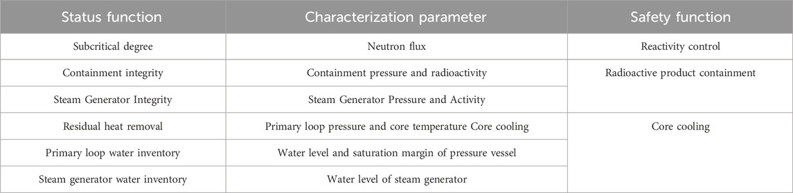
Table 3. Six status function parameters of SOP procedure.
2.4.2 Upgrade of SOP procedures
In the initial study, the pressurizer safety valve of EDF power plant is “FISCHER”, which has no discharge function. To avoid abnormal function of the safety valve of the pressurizer, the control principle for such accidents is usually to keep the safety valve open, and this kind of operation mode is called “charging-discharging” mode. Wherein, “charging” refers to manually starting safety injection, and “discharging” refers to manually opening the safety valve of PZR and keeping the two functions open. After that, the “SEBIM” safety valve was installed on the unit. SEBIM refers to Pilot-operated safety valve. In addition, such valves can be opened and closed with water, which led to the change of the control principle to “filling overflow” mode. “Overflow” means to adjust the pressure of the primary loop by opening and closing the safety valve. It is considered that for 1000MW units, it is necessary to operate in the “charge overflow” mode, that is, manually start the safety injection, and then adjust the pressure of the primary loop by opening and closing the safety valve (Auvinen et al., 2005; Jung and Park, 2011). At the same time, the suggested period for repeatedly opening the safety valve during this process is 1 h. Later detailed research believed that the time limit for repeated opening should be estimated to be 20 min, which led to the shortening of the operation time of the “filling overflow” mode in the treatment procedures, that is, only the “overflow” state was maintained, which means that the safety valve was always opened. In fact, the purpose of this is to maintain the “charge discharge” mode when Tric (reactor core temperature) > 330°C is reached or the main pump is shut down for 20 min, that is to start the safety injection and open the safety valve of PZR manually. Then the open state is also to be maintained. In addition, in the previous procedure, the manual opening of the pressurizer safety valve was carried out after the safety valve automatically operated for a period of time. The safety valves were not all opened immediately. After the procedure was upgraded, this operation instruction was changed to be all opened immediately (AdamsMartin and Sattison, 1990; Auvinen et al., 2005).
2.4.3 Process of SOP after upgrading
After the loss of feedwater accident of steam generator, the important operations of operators are mainly divided into two parts: 1) To limit the generation of primary loop power: Stop the main pump and heater. 2) To remove the residual heat of the primary loop: Start the safety injection manually, open the safety valve of the pressurizer, and remove the residual heat through the break of the primary loop to try to recover the SG water supply. Therefore, after the accident, it is necessary to enter the SOP procedure according to the purple alarm indication and the guidance of SOP accident procedure first. And enter the ECP4 (sub-procedures of SOP) processing procedure after a series of judgments and operations when there exists the judgment standard that the water level of the steam generator is lower than - 1.8 m and the water level of the three steam generators is lower than - 10 m. As shown in Figure 6, THREE SGs level < −10 m indicates that the water inventory of the three steam generators is extremely low, that is, the steam generators have lost their functions.
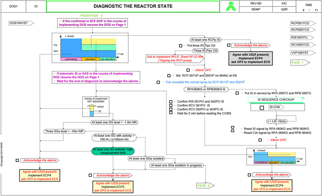
Figure 6. Dos procedures for accident.
After entering ECP4 procedure and conducting shutdown confirmation operation according to the guidance, manually convert the control mode of pressurizer spray into manual mode, and close the automatic controlling of the primary loop pressure (Reyes et al., 2004). Then stop the main pump according to the procedures. At the same time, to further reduce the thermal power of the primary loop and enter the sequence four of ECP4 procedure, manually open the safety valve of the pressurizer, as shown in Figure 7.
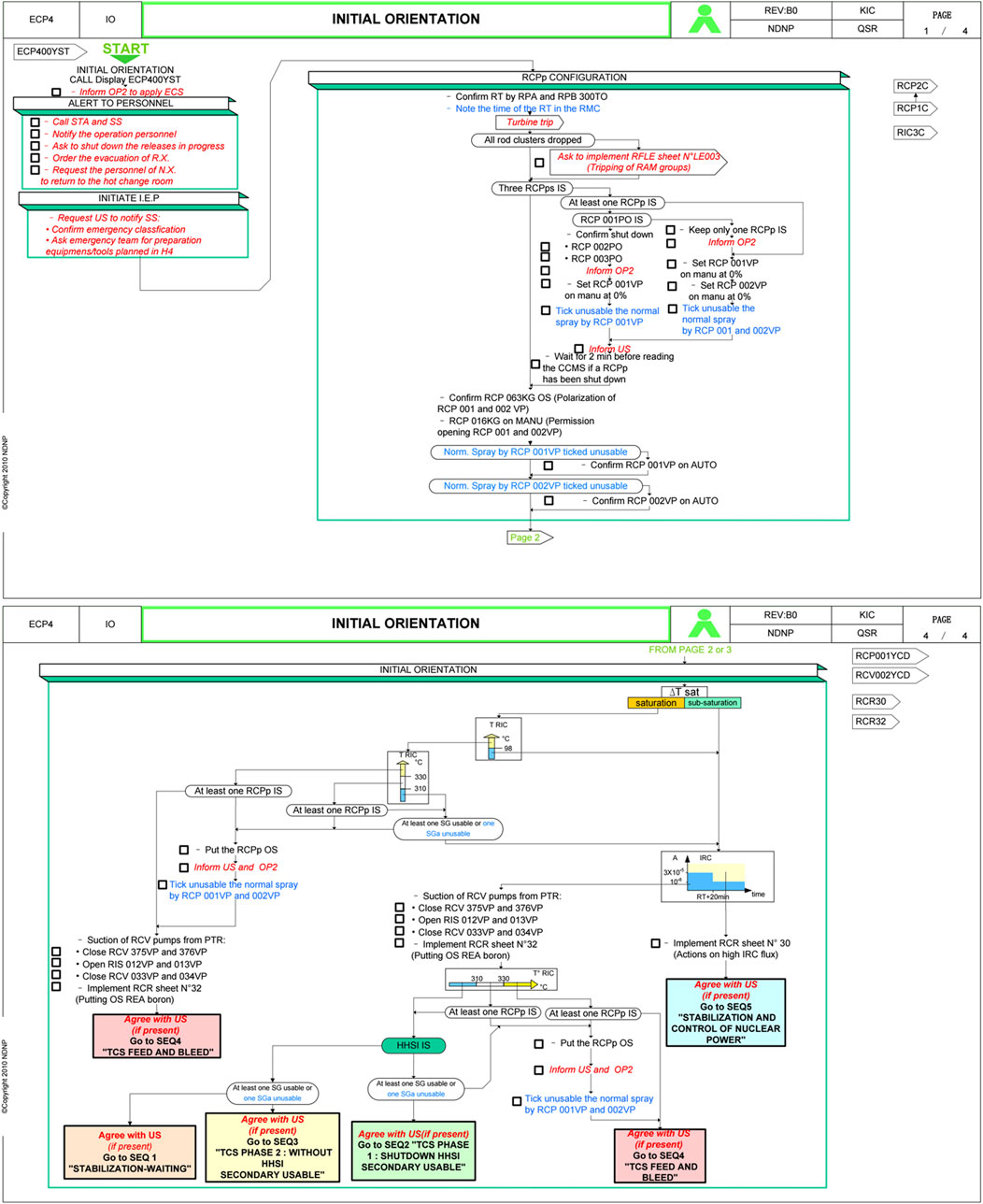
Figure 7. Ecp 4 procedure chart.
In Sequence 4, DEPRESSURLZATION BY PRL depressurizes the primary loop through the safety valve of the pressurizer. The specific operation process is to first open three groups of safety valves of the pressurizer: RCP017VP, RCP018VP, RCP019VP, RCP020VP, RCP021VP, RCP022VP. The heat in the primary loop is exported through the “charging and discharging” mode by artificially making small breaks, so as to protect the core, as shown in Figure 8.
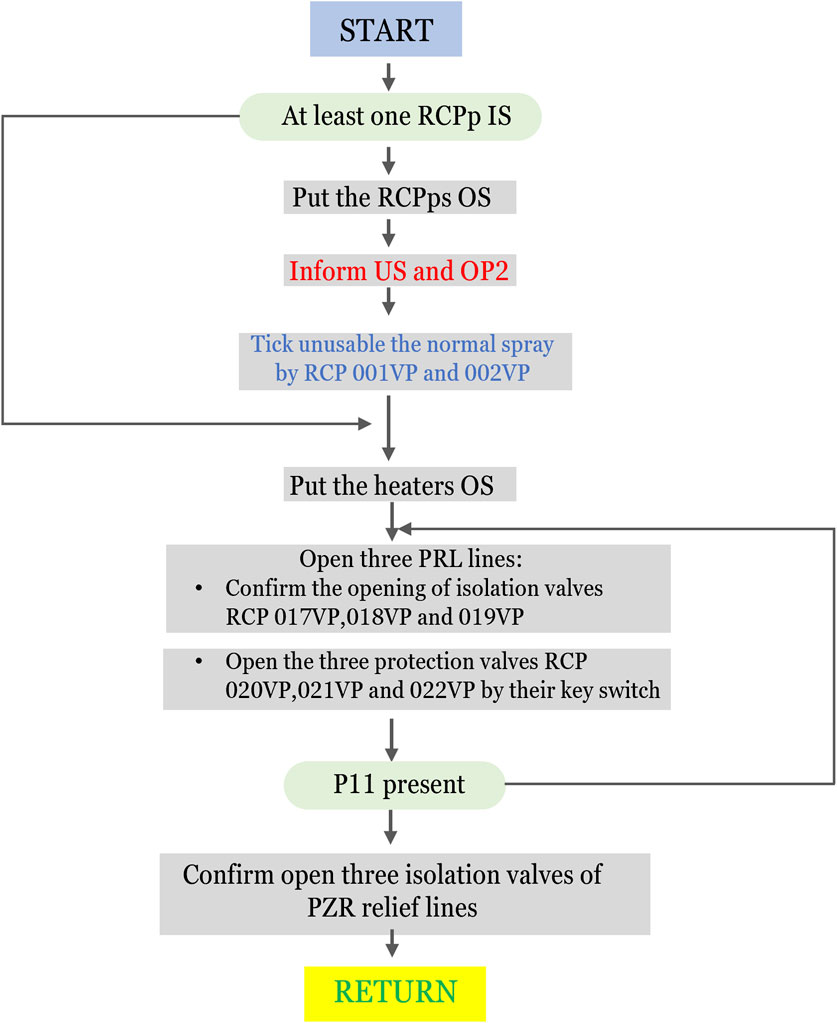
Figure 8. Step down module of sequence four.
2.5 Event assumption of primary initial accident
Based on the above model, the full scope simulator was used to simulate the total loss of feedwater accident of the steam generator, in which the operator was not intervened in the whole process. Assume that when T = 0s, main feedwater loss accident of steam generator occurs; After shutdown of the nuclear reactor, all electric and steam driven emergency feedwater pumps also failed. At the same time, the following assumptions are made:
1. Assume that the initial power of unit operation is 100%, and the unit operates stably without any abnormal conditions;
2. At 0s, the compressed air in the main feedwater control valve is suddenly lost, and the valve is in the fully closed state;
3. At 14.2s, low SG water level and SG steam water mismatch lead to the shutdown of the reactor;
4. At 14.2s, the auxiliary feedwater system fails to start, and the steam generator loses both main feedwater and auxiliary feedwater.
3 Result analysis
3.1 Transient analysis of accidents using non-upgraded procedures
Figure 9A shows the steam generator water level changes when an accident was handled using non-upgraded procedures. Due to the loss of compressed air, the main feedwater control valve in the steam generator water supply system will be placed in a safe position, that is, closed. This will also cause the water level of the steam generator to drop rapidly. When the water level reaches the lowest water level of the steam generator (dry state), the protection actions such as scram will be triggered. At this time, due to the reactor shutdown, the GCTa (GCTa refers to the steam bypass system of the secondary circuit of the nuclear power plant) system is also to be operated, and the pressure at the secondary side of the steam generator has been automatically controlled to be 7.85MPa, which leads to the reduction of the discharge flow of the steam generator, and then the decline rate of the water level of the steam generator began to slow down. When the steam generator pressure rises to the set value of GCTa pressure, the decline of the steam generator water level depends on the decay heat of the reactor. At this time, the steam generator water level is approximately equal to the decline of the slope. As the water in the steam generator continues to evaporate, the inverted U-shaped tubes begin to be exposed continuously, and the heat exchange capacity of the primary and secondary loops also decreases continuously. All these will cause the water level of the steam generator to drop slowly, and finally the steam generator will be completely evaporated.
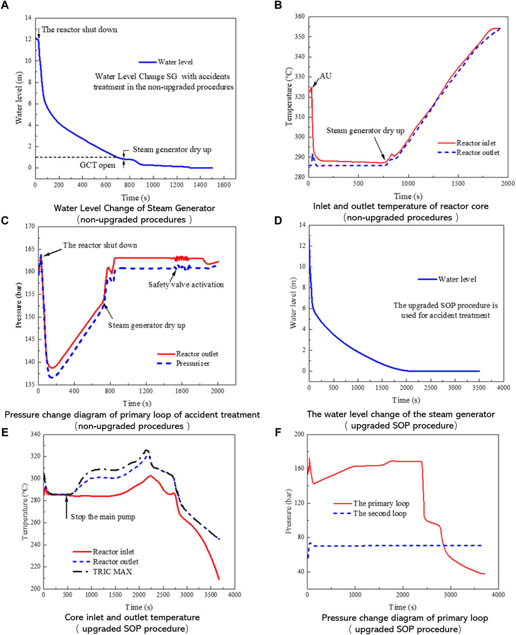
Figure 9. Summary of changes in relevant parameters (A) Water Level Change of Steam Generator (non-upgraded procedures) (B) Inlet and outlet temperature of reactor core (non-upgraded procedures) (C) Pressure change diagram of primary loop of accident treatment (non-upgraded procedures) (D) The water level change of the steam generator (the upgraded SOP procedure) (E) Core Inlet and outlet temperature (the upgraded SOP procedure) (F) Pressure change diagram of primary loop (the upgraded SOP procedure).
In the drying up process of the steam generator, the temperature of reactor inlet and outlet will also change accordingly. Figure 9B shows the change rule of inlet and outlet temperature of the reactor core that is not upgraded with the new procedures during the accident. In fact, at the beginning of the accident, although there was an emergency shutdown, the coolant flow did not change much due to the idling of the main pump. At the same time, the core outlet temperature will drop rapidly, and then the reactor coolant flow rate will also decrease, while the core outlet temperature will continue to rise. Therefore, the temperature difference and density difference of the coolant at the inlet and outlet of the core will increase accordingly. In addition, the increase of the coolant driving head will eventually be contributed to the formation of the natural cycle, and the average temperature of the primary loop will therefore become stable. In addition, when the steam generator is dried, the natural circulation will be terminated. At this time, the temperature of the primary loop increased with the continuous release and accumulation of core heat, and reached a state of near saturation at 1880s.
The change of core inlet and outlet temperature will also lead to the change of primary loop pressure. Figure 9C shows the pressure change diagram of the next loop during the accident. At the beginning of the accident, due to the reactor scram, the coolant temperature decreased, which caused the contraction of the primary coolant and the decrease of the primary pressure. At the same time, when the pressure reaches the fixed value of the low-pressure protection of the pressurizer, the electric heater will be automatically operated, and the pressure of the primary loop will also rise to 15.6 MPa. In addition, after the steam generator dries up, the rapid rise of the primary loop temperature causes the expansion of the primary loop coolant. The pressure also rises rapidly and finally reaches the action setting value of the safety valve of the pressurizer. The safety valve will open immediately and the primary loop pressure will be maintained between 16MPa and 16.6 MPa. When the steam bubble of the pressurizer disappeared, the safety valve was drained with water. Moreover, after the steam bubble is generated at the core outlet, the expansion rate of the coolant will become faster, and the action frequency of the safety valve will also become faster, but the safety valves of the pressurizer group can still be maintained between 16MPa and 16.6 MPa.
In general, in the total loss of coolant accident of steam generator, due to the large decay heat and the core heat that cannot be removed in time, the accident develops rapidly. However, more than 1 hour can also be used for the operator to intervene in response from the occurrence stage of the accident to the process when the core is exposed and damaged. If there is no intervention, the final safety injection flow cannot compensate the primary coolant discharged through the pressurizer safety valve, which will eventually lead to the core exposure, thereby entering the stage of serious accident.
3.2 Simulated disposal of accidents in upgraded SOP procedures
Figure 9D shows the water level change of the steam generator when the upgraded SOP procedure is used for accident treatment. It can be seen from the figure that the water level of the steam generator dropped rapidly at the beginning of the accident, and when the low water level of the steam generator was reached, the reactor scram and other protective actions were triggered. At this time, due to the operation of the steam bypass system (GCTa), the secondary side pressure of the steam generator is automatically controlled at 7.8 MPa. At the same time, the discharge flow of steam generator is reduced accordingly. In addition, when the steam generator pressure rises to the pressure setting value of the steam bypass system (GCTa), the primary loop decay heat shows a downward trend due to operator intervention. However, due to the constant existence of core decay heat, the water in the steam generator will continue to evaporate. Finally, the inverted U-tube was exposed, which led to the complete evaporation of the steam generator.
At the early stage after shutdown, the temperature was basically stable due to the operation of steam generator bypass. At the same time, after the operator stopped the main pump, the core heat through the natural circulation primary loop was exported, which led to the continuous rise of core temperature. After that, the core temperature continued to rise because the steam generator and the first group of SEBIM safety valves were not enough to remove the residual heat from the core. By starting the safety injection and manually opening the three SEBIM valves, the temperature in the equipment gradually decreases. The whole primary loop transits to the steam discharge stage, and the temperature of the primary loop also drops rapidly. As shown in Figure 9E, the temperature change trend of the core inlet and outlet.
After the steam generator completely loses feedwater, the reactor scram will lead to the decrease of primary loop pressure. After that, when the heat transfer function of the steam generator will be damaged, the temperature of the primary loop is also to rise rapidly, resulting in a rapid rise in pressure. This also enables the safety valve of the pressurizer to start relevant operation, which maintains the primary loop pressure between 16MPa and 16.6 MPa. When the core outlet temperature reaches 330°C, the manual startup of the safety valves of the two trains of safety injection and pressurizer will cause the rapid drop of the primary loop pressure. Due to the decrease of the primary loop pressure, the safety injection flow will continue to rise while the pressurizer discharge flow will continue to decline. Therefore, the loss rate of the working medium quality in the primary loop decreases, and the pressure drop trend also slows down. As shown in Figure 9F, the primary loop pressure change diagram. To summarize, the operation sequence comparison table of SOP before and after the upgradingare have many details on the differences, the most important is the following three steps, as shown in Figure 10.
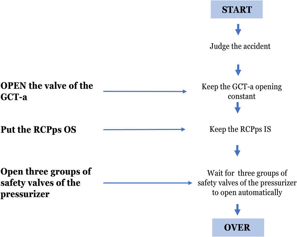
Figure 10. The main differences of SOP before and after the upgradingare
3.3 Suggestions for upgrading SOP procedures for steam generator with loss of feedwater
Due to the total loss of feedwater accident of the steam generator, there is no feedwater supplement to the steam generator. Therefore, before the steam generator dries up, how to make use of these limited water sources to export more heat is the key to ensure the safety of the unit. At this time, the operator should take all possible measures to ensure the heat removal from the reactor core. Therefore, according to the procedure, the main pump and the electric heater of the pressurizer are required to be shut down to reduce the heat source of the primary loop. Besides, the heat source of the primary system is only the core residual heat. In this case, the temperature change of the core only depends on the heat carrying capacity of the steam generator. Therefore, it is necessary to study how to control the steam generator parameters under limited water volume to obtain a large heat rate ratio (i.e., the ratio of heat carrying capacity to water consumption).
Under the same water enthalpy of the initial steam generator, the enthalpy of the exhaust steam needs to be controlled to the maximum value. According to the regulations, the steam generator will be under automatic control of the atmospheric discharge pressure of the steam generator. When the pressure is 7.85Mpa, the enthalpy of saturated steam is h = 2,760.9 kJ/kg, while the enthalpy of saturated water is h = 1310 kJ/kg. At the same time, the latent heat of vaporization of unit mass working medium is Δ h = 1,450.9 kJ/kg. It can be seen from the h-p diagram that when the possible enthalpy of saturated steam is the maximum, the corresponding saturated steam pressure is about 5.5 MPa. Therefore, when the pressure of the steam generator is reduced to 5.5MPa, the unit working medium steam can carry more heat. Meanwhile, the corresponding saturated steam enthalpy is h = 2,790.9 kJ/kg, and the saturated water enthalpy is h = 1170 kJ/kg, then Δh = 170 kJ/kg is obtained accordingly. That is, if the steam pressure is controlled at 5.5MPa, the unit working fluid can carry the additional 170 kJ heat besides the basic heat dissipation, and thereby deriving more heat from the limited water source.
After the shutdown of the nuclear reactor, the decay heat of the core continuously decreases during the water loss period of the steam generator, especially during the initial period of water loss. Therefore, under such characteristic of core decay heat, the amount of heat carried by unit steam is particularly important. In other words, as long as the same steam generator’s water capacity can carry more heat, a longer time can be won to delay the development of the accident. When the accident has occurred with the pressure reducing from 7.85 MPa to 5.5 MPa, the corresponding steam temperature will be reduced from 293.7°C to 267.0°C, with a decrease of 26.7°C. Since the valve of GCT-a is usually at 7.85MPa, the improvement is usually that the pressure setting of the steam drain valve of the steam generator can be set to 5.5Mpa in advance after the loss of feedwater accident of the steam generator. In addition, the automatic regulating function of the valve is activated to realize pressure reduction. On the basis of using different GCTa to control steam pressure during accident simulation, the effect of different GCTa on the accident process is recorded, and the calculation results are shown in Table 4.
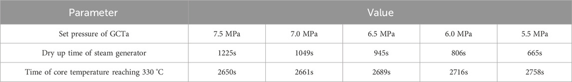
Table 4. Corresponding time change of GCTa setting of steam pressure.
According to the data in Table 4, it can be seen that reducing the steam generator pressure is helpful to delay the accident process. At the same time, the simulation results show that with the decrease of steam generator pressure, the drying time of the steam generator is also decreasing. All the above conclusions might be attributed to the decreasing steam pressure, which also results in the decrease of the corresponding steam saturation temperature. Accordingly, the coolant temperature also showed a downward trend, indicating that more coolant heat storage has been taken out, and the subcooling margin has increased. Because more heat needs to be brought out from the primary loop, the drying time of the steam generator is usually short. That is to say, the steam generator sacrifices its drying time to win more supercooling margin for the reactor, thus bringing out more core heat to protect the reactor. In addition, after the steam generator is burned out, its secondary side pressure is still maintained within the range of 5.5 MPa controlled by GCTa to prevent damage caused by excessive differential pressure of the steam generator tube sheet.
To sum up, when an accident occurs, it is necessary to immediately adjust the GCT-a valve to the fully open position, so as to reduce the pressure of the steam generator as much as possible, instead of staying at the safety setting value of 7.85Mpa, thus effectively delaying the process of the accident. However, the SOP procedure did not deal with this problem at the first time. On the contrary, GCT-a valve was not fully opened until the core outlet temperature reached 330°C. In fact, if the valve is set to fully open in advance, 5% more of the accident treatment time can be gained through the calculation results simulated by the simulator, which will win valuable time for the steam generator to restore the water source. Therefore, the upgraded SOP procedures is basically the same as before the upgrade, but The upgraded SOP procedures is more effective in dealing with This type of accident (total loss of feedwater).
4 Conclusion
By simulating the total loss of feedwater accident of steam generator in CPR1000 Nuclear Power Plant, this paper analyzes the whole accident process and the changes of main parameters in detail. First of all, after comparing the results of simulation experiments, the advantages of the upgraded SOP procedure for nuclear power plant accident handling procedures are verified. Secondly, according to the weaknesses of the upgraded SOP procedure, the relevant technicians can put forward constructive suggestions on changing the setting value of the bypass valve of the steam generator. At the same time, the results of several simulated accident experiments show that this change will strive for about 5% of the mitigation time for the nuclear power plant under this accident, and provide valuable reference for the subsequent upgrading of the nuclear power plant accident procedures. The specific conclusions are as follows:
(1) When the steam generator loses all feedwater, the operator should implement the key factors of accident intervention in SOP as required. If there is no intervention, the exposure and melting of the reactor core is inevitable, which will inevitably lead to the severe accident stage.
(2) The automatic control mode of the pressurizer is adopted in the first half of the accident without upgrading the SOP procedure, by which the heat in the core cannot be all brought out with the low reliability. Meanwhile, the upgraded SOP procedure can effectively take out the core heat by using the primary loop charging and discharging method, which is more effective, more reliable and more effective in dealing with the loss of feedwater accident of the steam generator, and can effectively extend the time from the core outlet temperature to the saturation temperature.
(3) Based on the weakness of SOP procedure, this paper puts forward relevant countermeasures and suggestions. According to the enthalpy pressure diagram of water vapor, the saturation pressure corresponding to the maximum enthalpy should be about 5.5 MPa. When the steam generator loses the total feedwater, the set pressure of GCTa should be set at 7.85 MPa. After the accident, the enthalpy value of the secondary side water is increased by modifying the set pressure value of GCTa, so that the limited feedwater can bring more heat. This measure can win about 5% more of the treatment time for the nuclear power plant under the accident.
Data availability statement
The raw data supporting the conclusions of this article will be made available by the authors, without undue reservation.
Author contributions
GW carried out Simulations and analysed the results as well as the writing of the paper. YZ and PW assisted in Simulated work and dealt with the Simulated data. FC and CZ set the guideline of this research and modified the background information. All authors contributed to the article and approved the submitted version.
Funding
The author(s) declare that no financial support was received for the research, authorship, and/or publication of this article.
Acknowledgments
This research is supported by Nuclear and Radiation Safety Center, Beijing, China. Additionally, the authors are thankful for the support of the China institute of atomic energy, Beijing, China.
Conflict of interest
The authors declare that the research was conducted in the absence of any commercial or financial relationships that could be construed as a potential conflict of interest.
Publisher’s note
All claims expressed in this article are solely those of the authors and do not necessarily represent those of their affiliated organizations, or those of the publisher, the editors and the reviewers. Any product that may be evaluated in this article, or claim that may be made by its manufacturer, is not guaranteed or endorsed by the publisher.
References
AdamsMartin, J. P. B., and Sattison, M. B. (1990). Frequency and consequences associated with a steam generator tube rupture event. Nucl. Technol. 90, 168–185. doi:10.13182/nt90-a34412
Auvinen, A., Jokiniemi, J. K., Lähde, A., Routamo, T., Lundström, P., Tuomisto, H., et al. (2005). Steam generator tube rupture (SGTR) scenarios. Nucl. Eng. Des. 235 (2-4), 457–472. doi:10.1016/j.nucengdes.2004.08.060
GuangmingMeifu, J.Li (2003). Study on beyond design basis accident for Qinshan Phase II NPP project. Nucl. Power Eng. (1), 44–45+48.
Jiao, F., Sun, W., Ma, G., Wu, Y., and Li, J. (2021). Event analysis for RCP pressure exceeding the requirement of operation technical specification of M310 series NPP. Nucl. Sci. Eng. 41 (4), 744–750.
Jung, W. D., and Park, J. K. (2011). Operator's performance time of emergency procedural tasks in SGTR scenario.
Khalil Ur, R., Shin, J., Zubair, M., Heo, G., and Son, H. (2013). Sensitivity study on availability of I&C components using Bayesian network. Sci. Technol. Nucl. Installations 2013, 1–10. doi:10.1155/2013/656548
Li, L., Zhou, Y., Wang, Z., Gu, H., Sun, Z., Li, Y., et al. (2022). Research on the filtration performance of pleated filters with rectangular and triangular structures through developed CFD code. Prog. Nucl. Energy 153, 104413. doi:10.1016/j.pnucene.2022.104413
Liu, X. (2022). Strategic positioning of nuclear energy in China's clean and low-carbon energy system. Industry Technol. Forum 21 (15), 12–15.
Luo, B., and Lin, J. (2010). Severe accident mitigation measure and severe accident sequence of CPR1000 nuclear power plant. Nucl. Power Eng. 31 (S1), 1–3+7.
Pan, C. (2017). Brief introduction to the principle of accident code for PWR nuclear power plants. Archit. Eng. Technol. Des. (13), 2692.
Reyes, Jr J., Woods, J., Groome, J., et al. (2004). Testing of passive safety system performance for higher power advanced reactors. Nucl. Eng. Des. 270, 113532.
Wu, G., Liu, Y., and Liu, Z. (2011). Application of the state oriented procedures in nuclear power plant station in our countries. Energy Eng. (1), 21–24. doi:10.16189/j.cnki.nygc.2011.01.013
Yi, Z. J. (2022). Research on application status and development trend of digital instrument and control system in nuclear power plant. Instrumentation 29 (12), 43–46.
Zubair, M., Ahmad, A., and Ahmed, I. (2017). Station black out concurrent with PORV failure using a Generic Pressurized Water Reactor simulator. Ann. Nucl. Energy 110, 1081–1090. doi:10.1016/j.anucene.2017.08.023
Keywords: SOP procedures, total loss of feedwater accident, full scope simulator, serious accident, safety analysis 1
Citation: Wang G, Zheng C, Zhang Y, Wu P and Chen F (2024) Simulated safety analysis of a total loss of feedwater accident in the steam generator of CPR1000 nuclear power plant. Front. Energy Res. 12:1252320. doi: 10.3389/fenrg.2024.1252320
Received: 03 July 2023; Accepted: 25 March 2024;
Published: 25 April 2024.
Edited by:
Hitesh Bindra, Kansas State University, United StatesReviewed by:
Jun Yang, Huazhong University of Science and Technology, ChinaIvo Kljenak, Institut Jožef Stefan (IJS), Slovenia
Copyright © 2024 Wang, Zheng, Zhang, Wu and Chen. This is an open-access article distributed under the terms of the Creative Commons Attribution License (CC BY). The use, distribution or reproduction in other forums is permitted, provided the original author(s) and the copyright owner(s) are credited and that the original publication in this journal is cited, in accordance with accepted academic practice. No use, distribution or reproduction is permitted which does not comply with these terms.
*Correspondence: Guanyi Wang, nscwgy@163.com