Coordinated frequency support strategy for VSC-HVDC integrated offshore wind farm system
 He Li1
  Kefei Yan
- 1Tongliao Power Supply Company, State Grid East Inner Mongolia Electric Power Co., Ltd., Tongliao, Inner Mongolia Autonomous Region, China
- 2Key Laboratory of Modern Power System Simulation and Control & Renewable Energy Technology, Ministry of Education, Northeast Electric Power University, Jilin, China
The large-scale offshore wind power integrated into the onshore power grid through voltage source converter-based high voltage direct current (VSC-HVDC) system is unable to provide inertia response and frequency support to the onshore power grid. To improve the frequency characteristics of the receiving-end power grid, a coordinated frequency control strategy combining VSC-HVDC and offshore wind power is proposed. The onshore converter adopts virtual inertia control, which uses DC capacitors to absorb or release energy for inertia support after the receiving-end grid is disturbed. Wind-farm-side VSC (WFVSC) obtains the frequency signal of the receiving-end power grid by detecting the local DC voltage. The offshore wind farm (OWF) transfers the frequency deviation into an additional power signal and sends it to the power controller to adjust the output, thereby performing inertia and primary frequency response. In addition, a secondary frequency regulation strategy for wind farms has been designed to achieve non-difference frequency regulation of the receiving-end power grid. Finally, a simulation model of VSC-HVDC integrated OWF system is constructed to demonstrate the proposed coordinated frequency control strategy for VSC-HVDC and OWF. The results indicate that the proposed control strategy can effectively enhance the frequency support capability of the receiving-end power grid.
1 Introduction
With the gradual deterioration of global environmental issues and the increasing depletion of traditional fossil fuels, clean, low-carbon, and sustainable energy generation technologies are rapidly developing, such as photovoltaic, wind, and microbial power generation (Kang et al., 2017; Son et al., 2021; Zahid et al., 2022) and so on. Wind power generation is the process of capturing wind energy through wind turbines, converting it into mechanical energy, and then converting mechanical energy into electrical energy. Photovoltaic power generation utilizes the photovoltaic effect at the semiconductor interface to directly convert light energy into electrical energy. For microbial power generation, electricity can be obtained from the decomposition of organic or inorganic substances through specific technologies including microbial fuel cells (Jung et al., 2023), microbial electrolysis cells (Pawar et al., 2022), and Microbial Electrosynthesis (Quraishi et al., 2021), etc. Offshore wind power, as an important technological direction for renewable energy, has advantages such as stability, high utilization, and low environmental impact, so it has become the focus of wind power resource development (Dreidy et al., 2017). Considering that offshore wind power is gradually showing characteristics such as large-scale and long-distance, the voltage source converter-based high voltage direct current (VSC-HVDC) with superior control performance provides an effective means to achieve the aggregation and transmission of offshore wind power (Alassi et al., 2019; Liu et al., 2023).
The scale of offshore wind farms (OWFs) connected to the receiving-end power grid through VSC-HVDC is constantly increasing, and partial synchronous generators (SGs) have been gradually replaced, resulting in low inertia level and poor frequency response ability of the receiving-end power grid (Zhu et al., 2013). Moreover, the power output of OWF is decoupled from the frequency of the low-inertia system, providing insufficient frequency support for the receiving-end grid, which will lead to the risk of frequency instability in the receiving power grid. Therefore, it is urgent to have further research on the control strategy for frequency stability improvement of VSC-HVDC integrated OWF system.
For OWF, in order to improve its active frequency support capability, relevant research on frequency regulation control strategies for wind turbines has been conducted in recent years, mainly from two aspects: rotor kinetic energy control and power reserve control (Yan et al., 2023). The rotor kinetic energy control is realized by changing the rotor speed of the wind turbine through additional inertial control, releasing the stored kinetic energy of the rotor to provide response power (Arani and El-Saadany, 2013). In (Van de Vyver et al., 2016) the frequency deviation of the power grid is filtered using a high pass filter to obtain the inertial power value and (Lu et al., 2019) achieves inertial response by adding a proportional link of RoCoF. However, due to the relatively small inertia of wind turbines compared to SGs, changing the rotor kinetic energy can only provide transient power support, and it is prone to excessive energy extraction, which can cause unit speed oscillation or even stall. Power reserve control is achieved by allowing wind turbines to retain a certain amount of power reserve during normal operation, enabling it to provide energy and power margin for frequency regulation. The main methods include speed control (Sun et al., 2010; Xu et al., 2018), pitch control (Wang et al., 2015; Prasad and Padhy, 2020), and a combination of speed and pitch control (Zhang et al., 2012). However, the de-loading operation state prevents the wind turbine from operating in MPPT mode, resulting in poor economic efficiency. In addition to participating in frequency regulation through wind farms, frequency support to the receiving-end grid can also be achieved by improving the control strategy of the receiving-end VSC. For VSC-HVDC systems, (Junyent-Ferre et al., 2015; Fang et al., 2018), utilize the energy storage characteristics of equivalent capacitors of VSC to participate in system frequency regulation and control the DC voltage to absorb or release power of the DC capacitor. Because of the limited energy stored by DC capacitors, VSC can only provide short-term inertia support. To enable the converter station to have primary frequency regulation capability, an essential power source is required, such as a wind farm or an asynchronous connected AC power grid.
Given that the VSC-HVDC system decouples the OWF frequency from the onshore power grid frequency, the OWF cannot directly respond to frequency changes in the onshore power grid. Therefore, coordinated control is required between the OWF and VSC-HVDC, which mainly includes communication mode and no communication mode (Lu et al., 2021). The main idea of the communication-based coordinated control method is to directly transmit the real-time frequency information of the onshore power grid to the OWF through the communication channel, and then achieve frequency support by adjusting the active power output of OWF (Pipelzadeh et al., 2012; Liu and Chen, 2015a). A coordinated control strategy for OWF integrated system through VSC-HVDC is proposed in (Liu and Chen, 2015a; Junyent-Ferre et al., 2015), which combines the kinetic energy of wind turbines with the electrical energy of DC capacitors in grid side VSC (GSVSC), to improve the overall equivalent inertia of the system. A coordinated control scheme without communication is proposed in (Phulpin, 2012; Liu and Lindemann, 2018), in which, the onshore grid frequency is fed back to the wind farm side converter station (WFVSC) through GSVSC, and the frequency support of OWF can be achieved by associating the DC voltage with the onshore grid frequency information. The above studies have focused on the issue of wind farms and VSC-HVDC participating in inertia response and primary frequency regulation from different perspectives. However, there is relatively little research considering the active participation of OWF in secondary frequency regulation. Thus, it is necessary to further explore the regulatory potential of VSC-HVDC integrated OWF system, to actively assume the responsibility of system secondary frequency regulation and achieve long-term stability of system frequency.
This paper proposes a coordinated control strategy using energy storage of DC capacitor and power reserve of OWF to provide inertia response, primary and secondary frequency regulation. Firstly, the energy storage characteristics of DC capacitors are analogized with the characteristics of SG rotors. A virtual inertia control for DC voltage is established to improve the inertia level of the receiving-end power grid, and the virtual inertia control parameters are designed considering the limitations of DC voltage and frequency. Secondly, by using DC voltage to transmit the frequency signal from the receiving-end power grid to OWF side, and then the virtual inertia and primary frequency regulation control for OWF are established based on the power reserve control so that OWF could realize active participation in frequency regulation by adjusting its active power reference value. Moreover, for OWF, an adaptive wind power control strategy is designed to achieve automatic switching between variable speed and pitch control. Finally, the feasibility and effectiveness of the proposed coordinated control strategy are verified in an OWF-integrated system via a two-terminal VSC-HVDC.
2 Configuration of VSC-HVDC integrated OWF system
The structure of the VSC-HVDC integrated OWF system is shown in Figure 1. OWF consists of multiple double-fed induction generator (DFIG) and the AC power generated by OWF is converted into high-voltage DC power via centralized wind-farm-side VSC (WFVSC), which can then be transmitted to the onshore grid-side VSC (GSVSC) through submarine cables. For DFIG, rotor-side converter generally adopts MPPT control mode, while the grid side converter adopts constant DC voltage control to ensure stable DC voltage inside the DFIG. OWF has the weak voltage self-built capability of wind power is weak and has no ability of black start. In order to ensure the stable operation of OWF integrated vis VSC-HVDC, WFVSC needs to provide stable AC voltage and frequency for OWF, thus, WFVSC need to adopt constant AC voltage control and constant frequency control. GSVSC accepts DC power and converts it into AC power, which generally adopts constant DC voltage control and constant reactive power control to maintain DC voltage stability. The receiving-end power grid contains a certain capacity of synchronous machines and loads. Due to the large-scale integration of offshore wind power, the proportion of conventional synchronous machines is relatively low, forming a typical low-inertia system with poor inertia and frequency response capabilities. With conventional control mode, OWF and VSC-HVDC do not participate in the frequency response of the onshore AC grid, and OWF cannot provide inertia and frequency support to the onshore power grid through VSC-HVDC. Therefore, to improve the frequency support ability to receiving-end power grid, it is necessary to tap into the flexible adjustment potential of VSC-HVDC and offshore wind power.
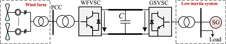
FIGURE 1. Structure of VSC-HVDC integrated OWF system.
3 Inertia and frequency regulation control strategy for VSC-HVDC integrated OWF system
This section proposes a coordinated frequency control strategy for OWF and VSC-HVDC, including a virtual inertia control strategy for VSC-HVDC and the inertia response and frequency regulation control strategy based on non-communication methods for OWF. The receiving-end converter station utilizes the charging/discharging characteristics of its capacitor to change the DC voltage to provide inertia response to onshore power grid. OWF can instantly perceive the frequency changes of the onshore power grid through DC voltage feedback, and change the power reference value through additional control, thereby automatically adjusting the speed and pitch angle to achieve inertia response and primary and secondary frequency regulation.
3.1 Virtual inertia support from the DC capacitor of VSC-HVDC
There are two control method for VSC to realize inertia support, namely, grid-following (GFL) control like (Liu and Chen, 2015b) and grid-forming (GFM) control like (Xiao et al., 2023). The implementation of GFM control requires sufficient and stable power sources, while OWF cannot provide stable power output considering the influence of wind speed. Moreover, for the VSC-HVDC integrated OWF system in this paper, if GFM control is adopted at the onshore VSC, no converter station at either side can achieve constant DC voltage control. Therefore, in this paper, the GFL control is adopted for onshore VSC.
The inertia response process of synchronous generators can be described by the rotor motion equation:
where Hg is the inertia time constant of the synchronous machine, f is the actual frequency of the AC power grid, PM is the mechanical power and PE is electromagnetic power.
The DC capacitor of VSC can ensure the stability of DC voltage and energy conservation within the VSC-HVDC system. The magnitude of DC voltage can reflect the power changes of the receiving end AC power system. Based on the dynamic characteristics of DC capacitors, the relationship between DC voltage and active power at the receiving-end grid can be expressed as
where Pin and Pout are the active power flowing into and out of GSVSC, respectively. udc is DC side voltage. SVSC is the rated capacity of VSC. Cdc is the equivalent capacitance of VSC.
Comparing Eqs 1, 2, the DC capacitor energy storage characteristics in the VSC-HVDC system are similar to the energy storage characteristics of the generator rotor. The DC capacitor voltage in the VSC-HVDC system can be equivalent to the generator rotor, and the DC voltage can be analogized to the grid frequency so that the DC capacitor could have the inertia response characteristics shown as Eq. 3.
where Hvsc is the virtual inertia time constant of the DC capacitor.
By integrating both sides of the equal sign in Eq. 6, the relationship between DC voltage and AC frequency can be obtained as Eq. 4
where f0 and udc0 are the rated values of AC power grid frequency and DC voltage, respectively.
According to Eq. 5, the relationship between inertia constant, DC voltage, and system frequency can be reformulated as
Under the same DC system parameters, the larger the inertia simulated by the converter station, the greater the DC voltage amplitude change, and the higher the frequency stability of the power grid. Therefore, the virtual inertia constant of VSC should be set appropriately to prevent the DC voltage from exceeding the limit. According to the allowable frequency deviation (Δfmax = ±0.5 Hz) of the power grid and the maximum allowable deviation of DC voltage, the inertia constant Hvsc could be designed as:
“Referring to actual engineering, the empirical value of de DC voltage deviation is selected as ±0.05∼0.1 p.u. In this paper the Δudc,max is set as ±0.1 p.u.”
By combining Eqs 5, 7, the required DC voltage reference value for simulating the set inertia can be concluded by Eq. 8.
3.2 Frequency support strategy of OWF
Due to insufficient frequency regulation reserve provided by SGs in the receiving-end grid, it is necessary for the WFs to have the ability to actively participate in frequency regulation and reduce the frequency deviation of the system. In this subsection, WTs achieve quantitative de-loading through a coordinated de-loading control strategy of variable speed and pitch, and on the basis, a frequency regulation control strategy for OWFs without communication is designed.
3.2.1 Power reserve implementation for OWF
WTs operating under MPPT status always maintain maximum output and have no capability to provide active power continuously. Only relying on the kinetic energy of the WT rotor is not enough to satisfy the frequency regulation requirements, thus WTs should keep a certain amount of power reserve in advance to achieve power support for the receiving-end grid.
In this paper, DFIG is adopted as the WT. The active power output of the WT with d% (usually 10%–20%) de-loading can be expressed as Eq. 9
Where Popt, Pdel, Cp,del, and Cp,opt are the power output and rotor power coefficient of WTs at the state of MPPT and d% de-loading operation, respectively. ρ denotes the air density, V denotes the wind speed and R denotes the wind turbine rotor radius. When ρ and V remain constant, by controlling the rotor speed and pitch angle, Cp can be controlled to achieve quantitative de-loading operation of the WT.
For different wind speed scenarios, variable rotor speed and variable pitch control should be reasonably used to achieve quantitative de-loading of OWF. The principle is shown in Figure 2.
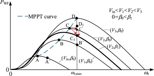
FIGURE 2. Schematic diagram of the de-loading process for wind turbine.
In Figure 2, curves (Vin, 1, 3, β0) represents the relationship between the output power and the rotor speed of the wind turbine with different wind speed and the same pitch angle. The curves (V2, β0) and (V2, β1) show the relationship between the output power and the rotor speed of the wind turbine with the same wind speed but different pitch angles. The curve ABCD represents the wind power curve when the wind turbine operates at a maximum power point tracking (MPPT) state. The OWF should adopt a power reserve control strategy applicable to the full wind speed, that is, automatically coordinate the de-loading operation mode of overspeed and pitch according to the wind speed, so that the wind turbine can constantly generate the active power of (1-d%) Popt. The main idea is: 1) when the wind speed is lower, as (V1, β0) shown in Figure 2, d% de-loading can be achieved through overspeed control, i.e., curve AA′. After de-loading, the rotor speed is still less than the maximum speed ωr,max. 2) When the wind speed further increases, as (V2, β0), the de-loading is first achieved through overspeed control, i.e., curve CC′, and when the speed increases to the maximum limit ωr,max, the rotor speed will no further continue to change. At this time, by controlling the pitch angle increasing to β1 to further realize d% de-loading of the wind turbine, i.e., curve C′C1. 3) When the wind speed is greatly high, as (V3, β0), the de-loading can be achieved directly through pitch control, the pitch angle increases, and the rotor speed is unchanged keeping at maximum speed ωr,max during the de-loading process. i.e., curve DD1.
3.2.2 Additional frequency control method for OWF
3.2.2.1 Virtual inertia and primary frequency regulation control
OWFs are generally scores or even hundreds of kilometers away from the onshore power grid. The method that transmits frequency signals over long distances through communication systems has a longer communication delay. Therefore, by establishing the relationship between the frequency of the receiving-end grid and the DC voltage, the frequency information of the receiving-end grid can be transmitted to the wind farm side using the DC voltage as the carrier. According to Eq. 5, the relationship between the frequency of the receiving-end power grid and the DC voltage can be reorganized into Eq. 10.
In Eq. 10, except for the Udc, all other parameters are constants representing system parameters or pre-set parameters. Therefore, the remote OWF only needs to measure the local DC voltage to obtain the frequency signal of the receiving power grid.
Introducing virtual inertia and droop control into the active power control link of DFIG to simulate the inertia response and primary frequency regulation process of synchronous machines. When the frequency of the receiving power grid fluctuates, the frequency regulation power provided by DFIG can be expressed as Eq. 11.
where ΔPwf is the additional frequency regulation power of the DFIG. Rwf and Hwf are the adjustment coefficient and virtual inertia of DFIG, respectively.
When the above-mentioned coordinated control strategy is applied for OWF and VSC-HVDC, the frequency response process of the receiving-end power grid can be expressed by the sorted rotor motion equation as Eq. 12 and Eq. 13.
where Sg, Svsc, and Swf are the total capacity of SG, VSC, and OWF.
From Eq. 12, the equivalent inertia of the receiving-end power grid increases after adopting the coordinated control of OWF and VSC-HVDC, which can reduce the frequency deviation of the receiving-end power grid after disturbance. Due to the pre-de-loading operation, the virtual inertia provided by the OWF is no longer limited by the rotor speed, and the wind farm can provide primary frequency regulation support for the receiving-end grid.
3.2.2.2 Secondary frequency regulation of OWF
In order to enable OWF to have secondary frequency regulation capability, a proportional-integral control link is added to the active power control of the wind turbine to change the reference value of active power, thereby achieving the non-difference adjustment of frequency. The specific expression for the secondary frequency regulation process of OWF is shown in Eq. 14
where P* w, ref is the reference values of active power for secondary frequency regulation. kp and ki are proportional and integral coefficients, respectively.
From an economic perspective, we hold an attitude of “maximizing the generation” for the wind farms that have already been built. The participation of thermal power units in secondary frequency regulation will bring additional costs for the increase in power generation, and achieving secondary frequency regulation through wind power can not only achieve wind power utilization but also reduce power frequency regulation costs. Therefore, considering the factors of low-carbon and economic, we prioritize secondary frequency regulation through wind power, as long as wind farms have sufficient frequency regulation reserves. When the wind speed is low and the wind farm reserve is insufficient to satisfy the frequency regulation power demand, the synchronous machines would increase its power generation to restore the frequency to the rated state.
3.2.3 Adaptive control strategy for OWF participating in frequency regulation
The adaptive frequency control strategy for OWF is indicated in Figure 3. The proposed frequency control strategy of OWF includes three parts: adaptive power control, primary frequency regulation, and secondary frequency regulation. By adding primary and secondary frequency regulation control frequency control links, the output power reference of the wind turbine is changed. Then, combined with adaptive power control, the output power of the fan is changed by adjusting the rotor speed or pitch angle to achieve frequency support. In adaptive power control, an automatic switching process between variable speed and pitch control was designed to achieve changes in wind power output. During frequency regulation, the safety range of the actual rotor speed ωr is [ωr,opt, ωr,max]. Therefore, the minimum and maximum limit of ωr should be used as the critical condition for starting the pitch control.

FIGURE 3. Adaptive frequency control strategy for OWF.
When a low-frequency event occurs in the receiving-end power grid, wind turbine needs to increase power to participate in frequency regulation with the rotor speed decreasing. When the rotor speed is within the range of [ωr,opt, ωr,max], switch S1 is set to Ⅱ, and switch S2 is disconnected, so that the pitch angle control link does not need to start. When the rotor speed reference value reaches the critical value ωr,opt, if the increased power is still not satisfied to the frequency regulation power requirement, S1 is set to Ⅰ, switch S2 is closed, and the pitch angle control loop is activated. The power of wind turbines is further increased by reducing the pitch angle with the rotor speed keeping at ωr,max. Similarly, when a high-frequency event occurs, the wind turbine needs to reduce power to participate in frequency regulation and raise its rotor speed. When the rotor speed reference value increases to the critical value ωr,max, if the output power of wind turbines still needs to be reduced, switch S1 is set to Ⅲ, switch S2 is closed, and the pitch angle control loop is also activated. The power of wind turbines is further decreased by reducing the pitch angle with the rotor speed keeping at ωr,opt.
4 Simulation study
To verify the effectiveness and feasibility of the proposed coordinated control strategy, the simulation model of the VSC-HVDC integrated OWF system, as shown in Figure 1, was built in MATLAB/Simulink. In the receiving-end power grid, the total capacity of SGs is 500 MW, and the total installed capacity of OWFs is 500 MW. The relevant parameters of the simulation system are shown in Table 1. The related frequency regulation parameters of SG are given as follows: the inertia time constant is 6s, the primary frequency regulation coefficient is 20, the high-pressure turbine fraction is 0.3, and the reheat time constant is 7s.
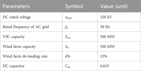
TABLE 1. Parameters of simulation system.
4.1 Verification of the coordinated frequency control strategy for OWF and VSC-HVDC
To demonstrate the effectiveness of the coordinated control strategies of WFs and VSC-HVDC, the following four cases are set up and comparative analysis.
Case 1:. None control strategy is adopted with only SG providing frequency support (Only SG).
Case 2:. DC capacitors provide virtual inertial support, based on Case 1 (VI).
Case 3:. OWF adopts inertia and primary frequency regulation, based on Case 2 (VI+PFR).
Case 4:. OWF participates in secondary frequency regulation, based on Case 3 (VI+PFR+SFR).
Under steady-state operation, the load of the power grid is 695MW, and the active power output of SGs is 400 MW. At initial time, the wind speed of OWF is set to 10 m/s, and the load increases by 35 MW at t = 10s. The simulation results of the dynamic response process of the system under different cases are shown in Figures 4, 5.
It can be seen that in Case 1, the frequency nadir of the receiving-end grid is 49.64 Hz, with a steady-state value of 49.82 Hz (as shown in Figure 4). All unbalanced power is borne by the SGs in the receiving-end grid, while the power of GVSC and wind turbine remains unchanged (as shown in Figures 5A–C). In Case 2, the power of GVSC first increases and then returns to its initial value, and the power change of SG slows down correspondingly. Compared with Case 1, the quasi-steady-state values of frequency in Case 2 are the same as that Case 1, but the initial frequency change rate is lower. The results indicate that the DC capacitor can provide short-term inertial support to in receiving end power grid, effectively suppressing the frequency change rate in the initial stage after the power disturbance.
In Case 3, the OWF detects the DC voltage deviation signal and increases its output by reducing the rotor speed to provide inertia and primary frequency regulation support for the receiving-end power grid, as shown in Figure 5D. Simultaneously, compared with Case 1 and Case 2, the increase of SG power is reduced, which indicates the frequency control of OWF also partly alleviates the frequency regulation pressure of SG. Although the frequency nadir and quasi-steady-state value of the frequency in Case 3 are significantly higher than those of Case 1 and 2, and the frequency can recover to stability more quickly, there is still a steady-state frequency deviation in the receiving-end power grid after primary frequency regulation. In Case 4, the secondary frequency regulation of OWF starts at t = 50 s, and the output power is first increased by raising the rotor speed, as shown in Figure 5E. At 76 s, the rotor speed reaches the maximum limit, and the wind turbines further increase the power by increasing the pitch angle (as shown in Figure 5F), gradually eliminating the frequency deviation and realizing non-difference frequency regulation of the receiving-end power grid. At the same time, the output power of the SG in Case 3 gradually returns to the initial value. The above results show that the proposed control strategy of OWF and VSC-HVDC can effectively improve the frequency support ability of the receiving power grid, which can not only improve the dynamic response performance of frequency, but also restore the frequency to the steady-state value before disturbance through secondary frequency modulation, achieving none-difference adjustment.

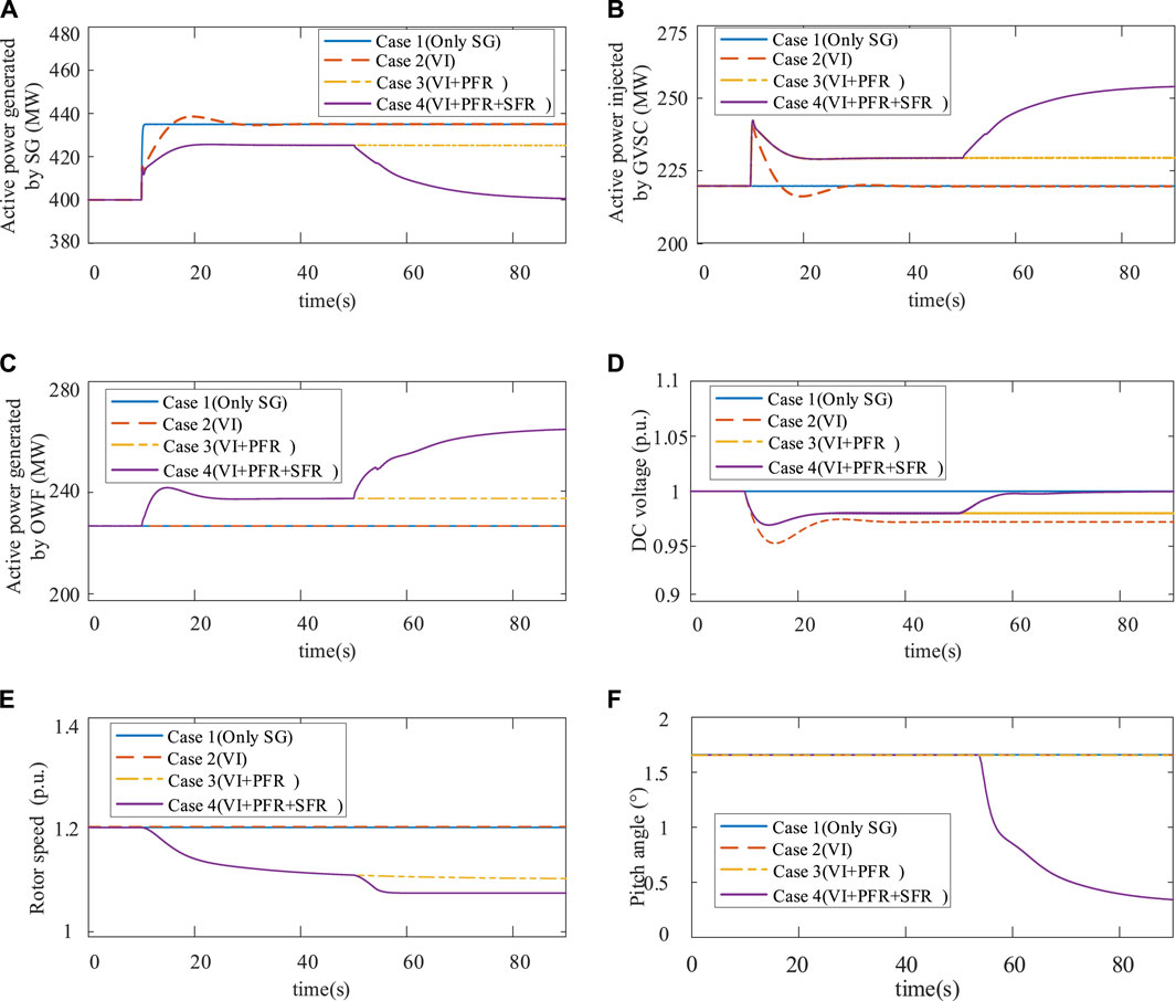
FIGURE 5. Comparision of the simulation results under Cases 1–4: (A) Active power generated by SG; (B) Active power injected by GVSC; (C) Active power generated by OWF; (D) DC voltage; (E) Rotor speed; (F) Pitch angle.
4.2 Applicability of the proposed strategies with different wind speed scenarios
In order to further verify the applicability of the proposed control strategy under different wind speeds, Case 5 and Case 6 were set, with wind speeds of 8 m/s and 11 m/s, respectively. The control strategy in Cases 5 and 6 is the same as Case 4, and the comparison of the system dynamic processes in different cases under the same disturbance conditions is shown in Figure 6.
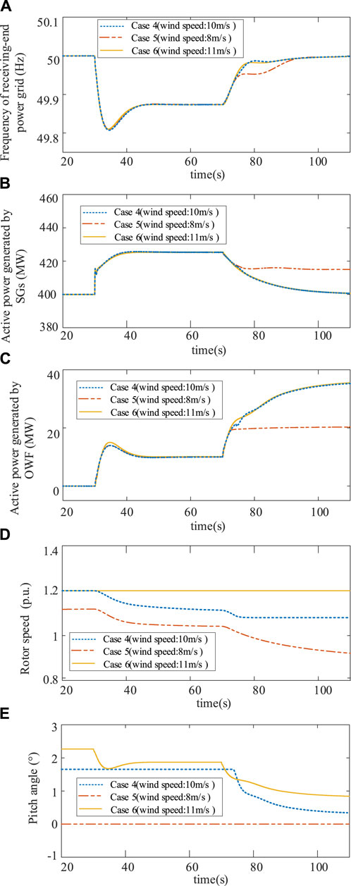
FIGURE 6. Comparision of the simulation results under Cases 4–6: (A) Frequency of receiving-end power grid; (B) Active power generated by SG; (C) Active power generated by OWF; (D) Rotor speed; (E) Pitch angle.
Figure 6A shows that, in all cases, the steady-state frequency of the receiving-end power grid can return to 50 Hz, when the frequency regulation is completed. However, as shown in Figures 6B, C, the secondary frequency regulation power is undertaken by both OWF and synchronous units in Case 5. The reason is that the reserve capacity of OWF is relatively small with low wind speed, and the maximum power increase of OWF is not enough to fully offset the unbalanced power. Figures 6D, E indicate that in Case 5, primary and secondary frequency regulation of OWF can be achieved solely by changing the rotor speed, while the pitch angle remains unchanged throughout the entire process because the speed remains within the range of [ωr,opt, ωr,max] before and after the frequency regulation process. In Case 6, the rotor speed does not change during the frequency regulation process, which is for the reason that the optimal speed of the wind turbine is the maximum limit of 1.2, with a wind speed of 11 m/s. Therefore, it is impossible to realize power increase by reducing the rotor speed even during the primary frequency regulation process. In order to provide the frequency regulation power, the pitch angle must be reduced from 2.27° to 1.87° for primary frequency regulation and continue to decrease to 0.85° for secondary frequency regulation. The above results indicate that the proposed strategy can enable OWF to participate in frequency regulation by automatically coordinating the pitch angle and rotor speed to adjust the output power, ensuring its applicability to different wind speed scenarios.
5 Conclusion
For the problems of low inertia and poor frequency regulation ability of the OWF integrated system, this paper proposed a coordinated frequency control strategy for OWF and VSC-HVDC. The proposed strategy used a DC capacitor, DFIG rotor kinetic energy, and frequency regulation reserve to improve the inertia response, primary and secondary frequency regulation capability of the receiving-end power grid. The following conclusions could be obtained through simulation analysis:
(1) When the receiving-end power grid has a power disturbance, the proposed control strategy can use the DC capacitor to provide inertial support for the system and effectively suppress the frequency change of the power grid at the initial stage of disturbance. By establishing a coupling relationship between DC voltage and the frequency of the receiving power grid, eliminate the requirement for remote communication between converter stations and improving operational reliability.
(2) By adopting additional virtual inertia and droop control to change the power reference value of the wind turbine, and coordinating speed and pitch control, OWF can have the inertia response, primary and secondary frequency regulation capabilities similar as SGs. The proposed frequency control strategy can adapt to different wind speed scenarios, effectively improving the frequency stability of the receiving-end power grid.
(3) Compared with other control schemes, the proposed wind power frequency regulation control strategy can achieve the automatic switch between variable speed and pitch control according to the rotor speed during the frequency regulation process. In this strategy, speed control is prioritized, reducing the mechanical loss caused by pitch angle action.
Data availability statement
The original contributions presented in the study are included in the article/supplementary material, further inquiries can be directed to the corresponding author.
Author contributions
HL: Funding acquisition, Writing–review and editing. YL: Writing–original draft, Visualization, Validation. YM: Project administration, Supervision, Writing–review and editing. KY: Conceptualization, Methodology, Writing–original draft.
Funding
The authors declare financial support was received for the research, authorship, and/or publication of this article. This work was financially supported by Science and Technology Projects Supported by State Grid East Inner Mongolia Electric Power Co., Ltd. (SGMDTL00YWJS2200994).
Conflict of interest
Authors HL and YM were employed by Tongliao Power Supply Company, State Grid East Inner Mongolia Electric Power Co., Ltd.
The remaining authors declare that the research was conducted in the absence of any commercial or financial relationships that could be construed as a potential conflict of interest.
Publisher’s note
All claims expressed in this article are solely those of the authors and do not necessarily represent those of their affiliated organizations, or those of the publisher, the editors and the reviewers. Any product that may be evaluated in this article, or claim that may be made by its manufacturer, is not guaranteed or endorsed by the publisher.
References
Alassi, A., Bañales, S., Ellabban, O., Adam, G., and MacIver, C. (2019). HVDC transmission: technology review, market trends and future outlook. Renew. Sustain. Energy Rev. 112, 530–554. doi:10.1016/j.rser.2019.04.062
Arani, M. F. M., and El-Saadany, E. F. (2013). Implementing virtual inertia in DFIG-based wind power generation. IEEE Trans. Power Syst. 28, 1373–1384. doi:10.1109/tpwrs.2012.2207972
Dreidy, M., Mokhlis, H., and Mekhilef, S. (2017). Inertia response and frequency control techniques for renewable energy sources: a review. Renew. Sustain. Energy Rev. 69, 144–155. doi:10.1016/j.rser.2016.11.170
Fang, J., Li, H., Tang, Y., and Blaabjerg, F. (2018). Distributed power system virtual inertia implemented by grid-connected power converters. IEEE Trans. Power Electron. 33, 8488–8499. doi:10.1109/tpel.2017.2785218
Jung, S. P., Son, S., and Koo, B. (2023). Reproducible polarization test methods and fair evaluation of polarization data by using interconversion factors in a single chamber cubic microbial fuel cell with a brush anode. J. Clean. Prod. 390, 136157. doi:10.1016/j.jclepro.2023.136157
Junyent-Ferre, A., Pipelzadeh, Y., and Green, T. C. (2015). Blending HVDC-link energy storage and offshore wind turbine inertia for fast frequency response. IEEE Trans. Sustain. Energy 6, 1059–1066. doi:10.1109/tste.2014.2360147
Kang, H., Kim, E., and Jung, S. P. (2017). Influence of flowrates to a reverse electro-dialysis (RED) stack on performance and electrochemistry of a microbial reverse electrodialysis cell (MRC). Int. J. Hydrogen Energ. 42, 27685–27692. doi:10.1016/j.ijhydene.2017.06.187
Liu, H., and Chen, Z. (2015). Contribution of VSC-HVDC to frequency regulation of power systems with offshore wind generation. IEEE Trans. Energy Convers. 30, 918–926. doi:10.1109/tec.2015.2417130
Liu, H., and Chen, Z. (2015). Contribution of VSC-HVDC to frequency regulation of power systems with offshore wind generation. IEEE Trans. Energy Convers. 30, 918–926. doi:10.1109/tec.2015.2417130
Liu, X., Han, W., Liu, Y., Liu, Z., Su, M., et al. (2023). A coordinated voltage-frequency support method for VSC-MTDC integrated offshore wind farms system. IEEE Trans. Power Syst. 39, 1485–1502. doi:10.1109/TPWRS.2023.3274752
Liu, X., and Lindemann, A. (2018). Control of VSC-HVDC connected offshore windfarms for providing synthetic inertia. IEEE J. Emerg. Sel. Top. Power Electron. 6, 1407–1417. doi:10.1109/jestpe.2017.2751541
Lu, G., Lin, C., and Wu, Y. (2021). Comparison of communication-based and coordination-based frequency control schemes for HVdc-connected offshore wind farms. IEEE Trans. Ind. Appl. 57, 3352–3365. doi:10.1109/tia.2021.3079233
Lu, Z., Ye, Y., and Qiao, Y. (2019). An adaptive frequency regulation method with grid-friendly restoration for VSC-HVDC integrated offshore wind farms. IEEE Trans. Power Syst. 34, 3582–3593. doi:10.1109/tpwrs.2019.2901986
Pawar, A. A., Karthic, A., Lee, S., Pandit, S., and Jung, S. P. (2022). Microbial electrolysis cells for electro methanogenesis: materials, configurations, and operations. Environ. Eng. Res. 27, 200484. doi:10.4491/eer.2020.484
Phulpin, Y. (2012). Communication-free inertia and frequency control for wind generators connected by an HVDC-link. IEEE Trans. Power Syst. 27, 1136–1137. doi:10.1109/tpwrs.2011.2175817
Pipelzadeh, Y., Chaudhuri, B., and Green, T. C. (2012). “Inertial response from remote offshore wind farms connected through VSC-HVDC links: a communication-less scheme,” in 2012 IEEE Power and Energy Society General Meeting, San Diego, CA, USA, July 2012, 1–6. doi:10.1109/PESGM.2012.6345609
Prasad, R., and Padhy, N. P. (2020). Synergistic frequency regulation control mechanism for DFIG wind turbines with optimal pitch dynamics. IEEE Trans. Power Syst. 35, 3181–3191. doi:10.1109/tpwrs.2020.2967468
Quraishi, M., Wani, K., Pandit, S., Gupta, P. K., Rai, A. K., Lahiri, D., et al. (2021). Valorisation of CO2 into value-added products via microbial Electrosynthesis (MES) and electro-fermentation technology. Fermentation 7, 291. doi:10.3390/fermentation7040291
Son, S., Koo, B., Chai, H., Tran, H. V. H., Pandit, S., and Jung, S. P. (2021). Comparison of hydrogen production and system performance in a microbial electrolysis cell containing cathodes made of non-platinum catalysts and binders. J. Water Process Eng. 40, 101844. doi:10.1016/j.jwpe.2020.101844
Sun, Y., Zhang, Z., Li, G., and Lin, J. (2010). “Review on frequency control of power systems with wind power penetration,” in 2010 International Conference on Power System Technology, Zhejiang, China, October 2010, 1–8. doi:10.1109/POWERCON.2010.5666151
Van de Vyver, J., De Kooning, J. D. M., Meersman, B., Vandevelde, L., and Vandoorn, T. L. (2016). Droop control as an alternative inertial response strategy for the synthetic inertia on wind turbines. IEEE Trans. Power Syst. 31, 1129–1138. doi:10.1109/tpwrs.2015.2417758
Wang, Y., Bayem, H., Giralt-Devant, M., Silva, V., Guillaud, X., and Francois, B. (2015). Methods for assessing available wind primary power reserve. IEEE Trans. Sustain. Energy 6, 272–280. doi:10.1109/tste.2014.2369235
Xiao, H., He, H., Zhang, L., and Liu, T. (2023). Adaptive grid-synchronization based grid-forming control for voltage source converters. IEEE Trans. Power Syst., 1–4. doi:10.1109/TPWRS.2023.3338967
Xu, G., Hu, J., Guo, S., Chen, C., Li, C., and Bi, T. (2018). Improved frequency control strategy for over-speed wind turbines. Automation Electr. Power Syst. 42, 39–44.
Yan, K., Li, G., Zhang, R., Xu, Y., Jiang, T., and Li, X. (2023). Frequency control and optimal operation of low-inertia power systems with HVDC and renewable energy: a review. IEEE Trans. Power Syst., 1–17. doi:10.1109/TPWRS.2023.3288086
Zahid, M., Savla, N., Pandit, S., Thakur, V. K., Jung, S. P., Gupta, P. K., et al. (2022). Microbial desalination cell: desalination through conserving energy. Desalination 521, 115381. doi:10.1016/j.desal.2021.115381
Zhang, Z. S., Sun, Y. Z., Lin, J., and Li, G. J. (2012). Coordinated frequency regulation by doubly fed induction generator based wind power plants. IET Renew. Power Gener. 6, 38–47. doi:10.1049/iet-rpg.2010.0208
Keywords: offshore wind power, voltage source converter-based high voltage direct current (VSC-HVDC), inertia response, frequency support, coordinated frequency control strategy
Citation: Li H, Li Y, Meng Y and Yan K (2024) Coordinated frequency support strategy for VSC-HVDC integrated offshore wind farm system. Front. Energy Res. 12:1351353. doi: 10.3389/fenrg.2024.1351353
Received: 08 December 2023; Accepted: 07 February 2024;
Published: 21 February 2024.
Edited by:
Joshuva Arockia Dhanraj, Hindustan Institute of Technology and Science, IndiaReviewed by:
Shunfu Lin, Shanghai University of Electric Power, ChinaHuangqing Xiao, South China University of Technology, China
Sokhee P. Jung, Chonnam National University, Republic of Korea
Yuqing Dong, The University of Tennessee, Knoxville, United States
Copyright © 2024 Li, Li, Meng and Yan. This is an open-access article distributed under the terms of the Creative Commons Attribution License (CC BY). The use, distribution or reproduction in other forums is permitted, provided the original author(s) and the copyright owner(s) are credited and that the original publication in this journal is cited, in accordance with accepted academic practice. No use, distribution or reproduction is permitted which does not comply with these terms.
*Correspondence: Kefei Yan, 2201900224@neepu.edu.cn