Aerodynamic performance and wake development of NACA 0018 airfoil with serrated gurney flaps
 Zhehui Zheng1*
  Liu Chen2
- 1Energy and Power, University of Shanghai for Science and Technology, Shanghai, China
- 2University of Shanghai for Science and Technology, Shanghai, China
Improving the aerodynamic performance of the airfoil is important for optimising the rotor efficiency of the vertical axis wind turbines. As a simple passive control method, the Gurney flap is widely used to improve the aerodynamic performance of airfoils. In this paper, we study the impact of applying a novel serrated gurney flap with different heights on the NACA 0018 airfoil. An improved delayed detached eddy simulation method is adopted to investigate the lift-enhancing mechanism of the serrated gurney flap and the evolution of the downstream vortex system. The results show that the serrated gurney flap can effectively increase the airfoil lift coefficient and the lift-to-drag ratio. The improvement of the serrated gurney flap on the aerodynamic performance of the airfoil is more pronounced at moderate angles of attack. Further analysis of the downstream wake shows that a pair of vortices wraps over both sides of the airfoil and rotates perpendicular to the wake flow, which is produced by the columnar vortex upstream of the flap. These vortices mixed with the wake and accelerated the dissipation of the separated vortex on the suction surface of the airfoil.
1 Introduction
Vertical axis wind turbines (VAWTs) are gaining recognition in distributed wind energy due to their low manufacturing cost, low operation noise, and no need for piloting mechanisms (Rolin and Porté-Agel, 2018; Hansen et al., 2021). Despite the development of various VAWTs, a common limitation is their relatively low power coefficients compared to horizontal axis wind turbines (HAWTs), restricting their utilization (Anagnostopoulou et al., 2016). Symmetrical airfoils, such as the NACA 0015 and NACA 0018, are commonly used in VAWT blade design because they are expected to produce consistent aerodynamic forces during the blade rotation (Timmer, 2008). However, symmetrical airfoils have lower lift coefficients compared to cambered airfoils and are susceptible to dynamic stall at high angles of attack (AoAs) (Islam et al., 2011). Therefore, it is crucial to apply effective flow control methods to enhance the lift of VAWT blades.
Recently, a passive flow control technique known as the Gurney Flap (GF) has received significant interest in enhancing VAWT performance Chakroun and Bangga (2021). The device was originally a small flat tab (referred to as Plane Gurney flap or PGF) protruding perpendicular to the lower side of the airfoil, near the trailing edge. The optimal height of the flap is typically between 1% and 5% of the airfoil chord (Li et al., 2002). Liebeck (1978) applied the GF as a simple lift-enhancing device on commercial aircraft and rotorcraft. Wilbur et al. (2018) have shown that a GF with a height of 2% chord length of the airfoil can increase the lift by approximately 30%.
As a result, the PGF is widely applied in VAWTs due to its ease of implementation and high efficiency. Ismail and Vijayaraghavan (2015) optimized a combination of the GF and a semi-circular inward dimple on a VAWT blade, resulting in an approximately 35% increase in averaged tangential force in steady-state conditions and a 40% increase in oscillating conditions. Xie et al. (2016) applied the GF on the NACA 0012 blade and increased the maximum energy capture and efficiency by 22% and 15%, respectively. Yang et al. (2017) developed an active flow control technique for flapped airfoils on the VAWTs. The angle of the trailing-edge flap was controlled to suppress trailing-edge wake separation and dynamic stall. Bianchini et al. (2019) studied the application of the GF on the Darrieus-type VAWT and found that it is possible to yield up to 20% power gains in certain configurations. Yan et al. (2020) investigated the effects of the GF on the aerodynamic performance of a NACA 0018 airfoil, and they found that the GF significantly improved the power coefficient of a three-blade VAWT at low tip speed ratios (TSR). Ni et al. (2021) investigated the impacts of the GF and the parameters of solidity on the performance of VAWTs. They found that installing the GF on the upstream pairs of VAWTs can achieve higher flow velocity and benefit the power outputs of downstream turbines. Balduzzi et al. (2021) explored a 180-degree range of the AoA for the NACA 0021 airfoil with the GF used in the Darrieus VAWT and confirmed the enhanced aerodynamic properties using numerical and experimental means.
Furthermore, various efforts have been made to reduce the negative influences of the GF on the airfoil drag. Meyer et al. (2006) investigated the slotted flaps to reduce lift and drag while improving the lift-to-drag ratio. They found that the three-dimensional modifications of GF configuration change the two-dimensionality of the wake and reduce the drag by 12%. Lee (2009) investigated the use of perforated flaps, which resulted in a decrease in drag with a limited lift decrement.
In addition to the drag increase, the airfoil blade with GF flaps encounters a new problem of widened wake and enhanced vortices shedding from the trailing edge. These negative behaviours can lead to intensified wake noise and fluctuating lift (Meyer et al., 2007). The resulting trailing-edge noise is of a dipolar nature, and its acoustic power varies as a power of the velocity, with typical powers ranging between four and five (Turner and Kim, 2020; Zhang et al., 2022). Trailing-edge noise is highly significant at low Mach numbers due to the efficient scattering of the turbulent fluctuations over the solid trailing edges (Moreau and Doolan, 2013; Aihara et al., 2020).
Serrated or slotted trailing edges have been found to be effective in reducing the dominant trailing edge noise. Oerlemans et al. (2009) modified the trailing-edge serrations and successfully halved the wind turbine noise without adversely affecting the aerodynamic performance. Arce León et al. (2016) and Avallone et al. (2016) both investigated the statistical properties of the boundary-layer flow of a NACA 0018 airfoil with trailing edge serrations by time-resolved stereoscopic particle image velocimetry. Their results indicated that the reduced shear stress and the modifications of the turbulence spectra lead to beneficial changes in the unsteady surface pressure, resulting in a reduction of trailing edge noise. These findings highlight the potential of serrated or slotted trailing edges as a means to mitigate the negative impact of GFs on noise generation in VAWT blade designs.
Inspired by the success of the serrated trailing edge on a single airfoil, the design of the serrated Gurney flap (SGF) has gained significant interest among researchers. Neuhart (1988) demonstrated that the SGF could delay the boundary-layer separation on the suction surface of an airfoil. Van Dam et al. (1999) showed that, although the SGF results in a lower lift than the PGF, it can increase the lift/drag ratio. Experiments conducted by Gai and Palfrey (2003) in a wind tunnel on a NACA 0012 airfoil equipped with PGF and SGF with a 5% chord height showed a significant increase in the Cl, max in the presence of the flaps, but a slight decrease of the maximum lift-to-drag ratio. It should be noted that the GF height used in their study was greater than that used by previous researchers (Jain et al., 2015; Traub and Chandrashekar, 2016). Additionally, Garry and Couthier (2006) reported that a SGF with 90-degree segments, which reduces the projected frontal area to 50% of that of a PGF, is found to be more effective than a PGF in terms of lift-to-drag ratio.
Numerical investigations using computational fluid dynamic (CFD) tools have been conducted to study the flow over a stalled airfoil. The CFD methods based on Reynolds averaged Navier-Stokes (RANS) equations can generally provide acceptable predictions for the lift and drag coefficients of an airfoil before stall. However, the accuracy of RANS predictions for airfoil flow starts to decline after stall, as RANS methods are time-averaged and cannot resolve transient and significantly separated flow structures behind a stalled airfoil (Shur et al., 2008). In this case, the Large eddy simulation (LES) is a preferred method, although its computational cost often hinders comparative parametric studies. Alferez et al. (2013) used 160 million grids in the near-wall region to conduct an LES study of a stalled NACA 0012 airfoil, while Wang et al. (2018) performed LES investigations of blunt wind turbine airfoils at a Reynolds number of 2.62 × 10⁵ using more than 280 million cells in the simulations.
To tackle this challenge, an alternative detached-eddy simulation (DES) combining the RANS and LES methods is proposed to reduce computational costs Spalart et al. (1997); Shur et al. (1999). Delayed detached eddy simulation (DDES), an improved version of DES proposed by Spalart (2009), is a reliable tool for simulating stalled airfoils, e.g., the NACA 0012 airfoil at a 45° AoA (Im and Zha, 2014). Another approach is the improved delayed detached eddy simulation (IDDES), proposed by Shur et al. (2008), which combines DDES with an improved RANS-LES hybrid model aimed at the wall modelling in LES. Zhao et al. (2017) performed IDDES simulations of flows over an airfoil NACA634-021 with mild separation and dynamic stall. Benim et al. (2018) predicted the aerodynamics of a small HAWT using IDDES and obtained good agreement between numerical and experimental data. Lei et al. (2017a,b) investigated the aerodynamic performance of a two-blade vertical axis wind turbine using IDDES, and they found that the IDDES was a reliable method for studying the performance of VAWTs.
To gain a deeper understanding of the flow characteristics around a symmetric NACA 0018 airfoil with a serrated trailing edge (SGF), a comprehensive study of the aerodynamic performance and wake structures of the airfoil in the AoA range between 0° and 20° has been conducted systematically in this paper. The IDDES method has been employed to investigate the complex wake flow, particularly the fluctuating wake characteristics. Simulations have been performed for different flap heights, providing insights into the intricate wake flow behind the blunt serrated flap with sharp corners, which is the main contribution of this study.
2 Simulation setup
2.1 Airfoil model
Figure 1 shows the NACA 0018 airfoil attached with a GF of height h considered in this study. The flap is installed perpendicularly to the airfoil surface at the trailing edge. The chord length of the airfoil c = 250 mm, and the free stream velocity is 10 m/s. As a result, the simulation is conducted at a Reynolds number of 1.6 × 10⁵. The flow is considered incompressible, which is a representative flow condition for small VAWTs.
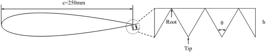
Figure 1. Schematic of NACA 0018 airfoil with SGF.
Three flap heights h are investigated in this study, corresponding to 0.02c, 0.04c, and 0.06c. As shown in Figure 1, the serrations angle θ = 60°. With full-depth cut-outs, the SGF reduces the frontal area by 50% compared to the PGF. Each flap has a thickness of 1 mm. The flow fields are extracted and analyzed within a rectangular region in the downstream plane and over the spanwise direction to cover three serration pitches. The averaging time period is chosen to be 10 vortex shedding periods.
2.2 Numerical solver
The flow around the NACA 0018 airfoil was simulated using the commercial CFD software FLUENT using the IDDES method. The modified Menter k-ω shear-stress transport (SST) two-equation turbulence model was chosen in the IDDES model due to its reliable predictions of aerodynamic forces and flow separation under adverse pressure gradients (Menter, 1994). A series of simulations are performed to evaluate the effect of SGF on the airfoil. For the transient simulation, a bounded second-order implicit time scheme with a time step of Δt = 5.0 × 10⁻⁵ s is applied.
2.3 Domain and mesh configurations
Figure 2A shows the computational domain and boundary conditions of the simulation. The domain extends 20c in the streamwise and vertical directions, respectively. In the streamwise direction, a prescribed free stream velocity of 10 m/s is imposed at the inlet boundary, while the ambient pressure outflow boundary condition is specified at the outlet. In the spanwise direction, the boundary is periodic and has a thickness of 3 serrated teeth (depending on the GF height). The surfaces of the airfoil and the flap are treated as non-slip walls.
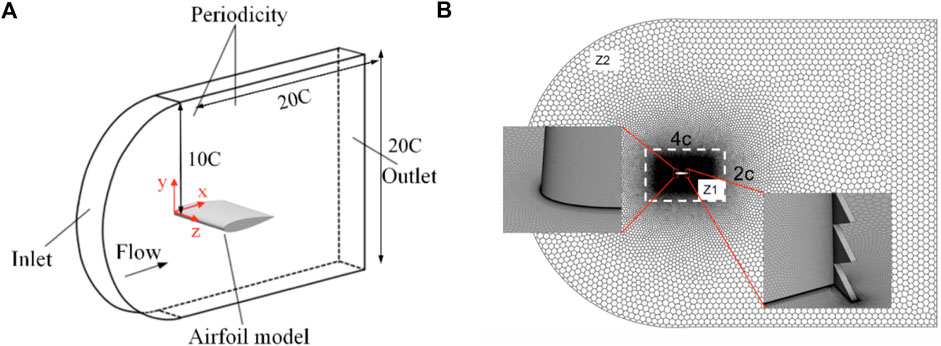
Figure 2. (A) Geometry features and main dimensions of the computational domain. (B) Zoom view of the computational mesh of the isolated aerofoil with SGF.
The mesh topology and distribution are shown in Figure 2B. The mesh is divided into two zones. Zone 1 (Z1 in Figure 2B), which is 4c in length and 2c in width, is refined to accurately capture the flow over the airfoil. A mesh size of 1 × 10⁻⁵ m at the first layer and a growth rate of 1.05 with 50 boundary layer meshes is chosen over the airfoil surface, ensuring that the condition of y+ ≤ 1 is met to resolve the flow details in the boundary layer. Outside the surface boundary layer, the mesh growth rate is set to 1.10, the curvature limitation is 10, and the maximum mesh size is 3 × 10⁻³ m in Z1. In Zone 2 (Z2), unstructured polyhedral meshes are used with a mesh growth rate of 1.30 from the border of Z1 to the border of the domain. Such a mesh configuration was found to have strong adaptability and high computational efficiency by previous researchers (Ye et al., 2023). Additional zoomed views of the mesh around the airfoil leading edge and the SGF are also shown in Figure 2B.
2.4 Simulation validations
2.4.1 Comparison with experiments
The simulation configuration in this study is validated by comparing with available experiment measurements of the baseline airfoil (Jacobs and Sherman, 1937), as well as the numerical results of Yang et al. (2017). Figure 3 displays the comparison of lift and drag coefficients of the baseline airfoil with respect to AoAs. For moderate AoAs (6° < α < 13°), the predicted lift and drag coefficients agree well with the experiment data.
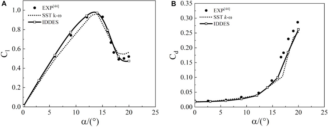
Figure 3. (A) Lift and (B) drag coefficient variations for the baseline airfoil.
Once the airfoil is stalled, the simulation predicts a decreasing trend in lift and an abrupt increase in drag for α > 13° operation cases. However, the predicted drag values are noticeably lower than the experimentally measured data when the AoA exceed 15°. This indicates a limitation of the numerical scheme in predicting the strong vortical turbulent flow separation. Similar unsatisfactory results were also reported by Yan et al. (2020) and Hassan et al. (2014), suggesting that the limitation of the numerical scheme in predicting vortical turbulent flow separation is a common challenge. In comparison, the IDDES model demonstrates a more accurate prediction of lift and drag coefficients compared to the SST k-ω model and is considered a reliable method to investigate the performance of NACA 0018.
2.4.2 Mesh convergence check
A mesh independence study was conducted for the NACA 0018 airfoil with and without the SGF at five successive refined meshes as shown in Figures 4A–C and listed in Table 1. The lift and drag coefficients of the baseline airfoil at α = 9° and 16° were used to assess the mesh independence before and after the stall. A deviation of less than 1% is observed when the total grid number is above 3.65 million. Considering the balance of the simulation accuracy and computation cost, the Case 4 mesh was found to be suitable for the simulation. In order to capture the wake development and evolution downstream of the SGF, the mesh was further refined in the vicinity of the flap parts in this study.
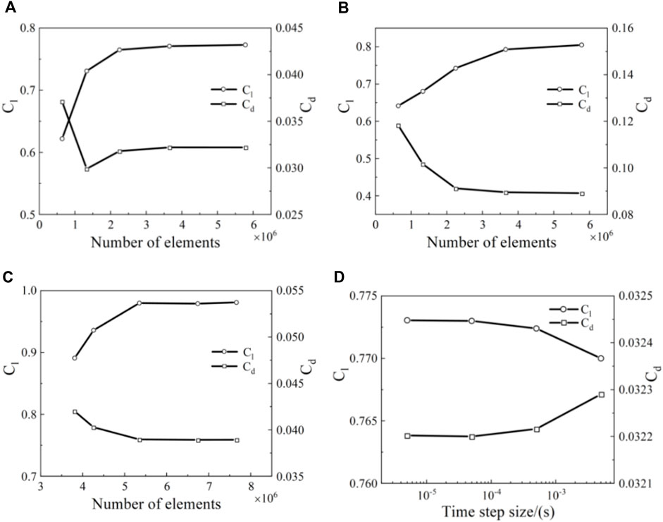
Figure 4. Mesh independence study of (A) the baseline airfoil at α = 9°; (B) the baseline airfoil at α = 16°; (C) the SGF airfoil at α = 9°. (D) The baseline airfoil with different time step sizes.
Table 1. Mesh parameters for the mesh independence study.
In all of the results presented in this study, the time step size is set to 0.0001 s by default. To investigate the effect of the time-step size on the value of the aerodynamic force coefficients, we compare the simulation results using four time-step lengths: 0.000005 s, 0.00005 s, 0.0005 s, and 0.005 s. As can be seen from Figure 4D, for the two smallest time steps analyzed, there is practically no difference in the results of either the lift coefficient or the drag coefficient. Therefore, for the further research reported in this paper, we used a time step of 0.00005 s, which is the time of the inflow passing through 1/500 of the airfoil chord length.
3 Results and discussions
3.1 Aerodynamic forces
3.1.1 Lift and drag
The effects of SGF height on the aerodynamic force coefficients upon NACA 0018 are depicted in Figure 5. Three flaps of different heights of 0.02c, 0.04c and 0.06c, are referred to as S1, S2, and S3 in Figure 5, respectively. A plane flap with a height of 0.06c (G3) is also added in Figure 5 as a comparison.
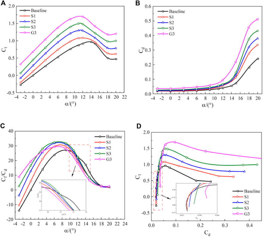
Figure 5. SGF effects on airfoil aerodynamic performance with respect to the AoA. (A) Lift coefficient verse AoA; (B) drag coefficient verse AoA; (C) lift-to-drag ratio verse AoA; (D) lift coefficient verse drag coefficient.
As we can see, all three SGFs increase the lift coefficients, Cl, across a range of AoAs from 0° to 20°. The lift increment grows as the AoA approaches the stalling point. In comparison to the baseline airfoil, the maximum lift coefficients of the airfoil with SGF (achieved at approximately α = 11°) are increased by 12.2%, 34.9% and 55.3% for S1, S2, and S3, respectively, resulting in slightly steeper lift slopes. The application of SGF reduces the lift stall angle from 14◦ to 12° for S1, and 11° for S2 and S3, respectively. Another notable finding in Figure 5A is that the SGF airfoil exhibits a positive lift at zero AoA, similar to the behaviour of a cambered airfoil. Similar results have been reported for symmetric NACA 0012 airfoil by Li et al. (2002).
On the other hand, the application of SGF also increases the drag of the airfoil, as shown in Figure 5B. We also observe that the stall angle decreases as the flap height increases. The SGF airfoils in general have higher Cd than the baseline one, although such differences are not significant before α = 11°. When the airfoil is stalled (α > 11°), the application of SGF sharply increases the drag coefficient.
Furthermore, the lift-to-drag ratio Cl/Cd is examined at different AoAs and is depicted in Figure 5C. Up to the pre-stall limit at α = 11°, the SGF airfoils generally have a higher lift-to-drag ratio than the baseline one. The maximum lift-to-drag ratio of the original airfoil is 27.08 at an AoA of 9°. In comparison, the SGF airfoils have the peak values of 29.63, 31.78, and 32.59 at AoAs of 9°, 6°, and 6°, respectively. However, the effects of SGF on airfoil performance gradually diminish and disappear as the airfoil stalled deeply. In this case, the flow separation occurs on the rear upper surface near the trailing edge. This result indicates that the SGF is capable of improving the pre-stall aerodynamic performance without significantly affecting the airfoil’s operational range.
The power output of a turbine is closely related to the designated lift coefficient. Therefore, it is interesting to compare the performance of a baseline airfoil and an SGF one at the same lift coefficient. As shown in Figure 5D, for the moderate lift coefficient (Cl < 1.0), at the same lift coefficient, the SGF airfoils have much higher drag coefficients than the baseline one. For example, at Cl = 0.2, the drag coefficients for S1, S2, and S3 are 0.0196, 0.0217, and 0.0258, while the drag coefficient of the baseline airfoil is 0.0192. It is important to note that in all SGF cases, the flap simultaneously increases the airfoil’s lift coefficient and lift-to-drag ratio. This result suggests that SGF is capable of enhancing the turbine’s output power by altering the flow behaviour around the airfoil.
Lastly, when we compared the serrated flap S3 with the plane one G3 with the same height in Figure 5, we can see that the serrated flap reduces both CL and Cd and increases the lift-to-drag ratio. This is also a favourable aerodynamic feature of the serrated flap in comparison with the traditional plane flap used in the previous studies (Ismail and Vijayaraghavan, 2015; Xie et al., 2016; Ni et al., 2021).
3.1.2 Surface pressure
The distribution of the surface pressure coefficient along the upper and lower surfaces of the airfoil provides important insights into the physical mechanism related to the observed lift enhancement with SGF. The results of three flapped airfoils at α = 6° and 20° are presented in Figure 6, along with the Cp distributions of the baseline airfoil. The pressure coefficient is defined as follows:
where p, ρ, and u0 are the static pressure, density and free-stream velocity, respectively.
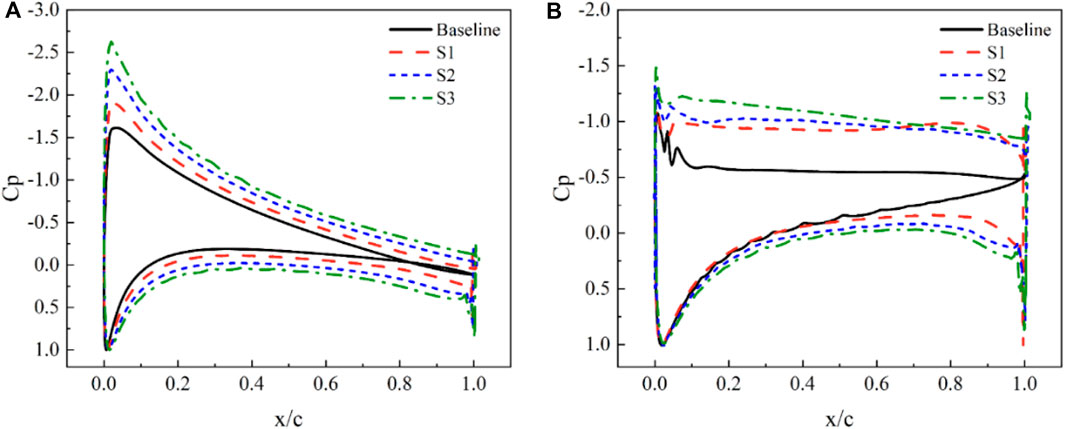
Figure 6. Pressure coefficient distributions over the airfoils. (A) α = 6°; (B) α = 20°.
In Figure 6A, the effects of the flap on the surface pressure distributions for a moderate AoA α = 6° are shown. The addition of a flap increases the low surface pressures due to flow deceleration before the flap blockage while reducing the upper surface pressures due to the streamwise down-wash flow and vortex-shedding activity behind the flap. As a result, the pressure differences between the lower and upper surfaces are increased, thus generating lift enhancement. Much of the lift increment is derived from a general increase in loading over the entire airfoil, accompanied by a higher leading edge suction peak. Additionally, the larger the flap height, the larger the pressure difference between the upper and lower surfaces of the airfoil. These effects have been interpreted by Lee (2009) as equivalent to a lengthened airfoil, which increases the flow turning near the trailing edge.
A comparison of the pressure distributions for various SGF heights at α = 20°, a deep stall condition, is presented in Figure 6B. The SGF considerably increases the loading of the airfoil, resulting in a significant area of flow separation on the suction surface. It is also noteworthy that much of the lift increment is caused by a general increase in loading and a higher suction peak. Furthermore, as the flap height is increased, higher loading is observed along the entire airfoil, particularly at low AoAs, which is more pronounced.
3.2 Wake development
As shown in Figure 7, the wake flows behind SGFs were extracted at four downstream locations to evaluate the flap effects on the near-wake dynamics, which is closely related to the airfoil performance and turbulent noise radiation. Mean velocity and turbulent kinetic energy (TKE) profiles are shown to analyze the wake development. To keep the discussion concise, Results are presented for two representative AoAs: 6° for pre-stall conditions and 20° for stalled conditions.
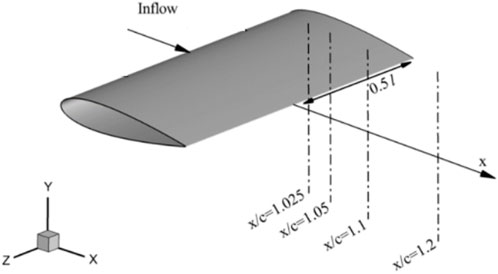
Figure 7. Airfoil coordinates allocating wake velocity depictions.
Figures 8A, B show the wake developments for the baseline and three flapped airfoils at α = 0°, on a x-y plane cutting through the serrated tip. Mean velocity and TKE profiles are plotted from x/c = 1.025 to 1.2. It is observed that the wake mean velocity profile initially maintains the self-similarity of the wake shape behind a baseline and S1 blade from x/c = 1.025 to x/c = 1.05, and gradually smooths out due to turbulent mixing in the downstream flow. However, as the height of the flap increases, the self-similarity is not observed in the wake of S2 and S3. The installation of the flap broadens the wake width and increases turbulence intensity. The downward movement of the wake center is caused by increased flow down-wash induced by the flap. Two velocity-deficit peaks are observed at x/c = 1.025 near the trailing edge, reflecting different boundary layer properties on the upper and lower surfaces. On the corresponding TKE profiles, a double-peaked profile is visible on the baseline airfoil until x/c = 1.20, while a single peak is observed on the low surface related to the flap height. The turbulence peak occurs at the flap edge, which is attributed to the flap blockage at the end of the lower surface and the abrupt flow turning around a sharp edge.

Figure 8. Wake profiles of the airfoil before stall: (A) Velocity at α = 0°; (B) TKE at α = 0°; (C) Velocity at α = 6°; (D) TKE at α = 6°.
The mean velocity and TKE profiles at α = 6° are presented in Figures 8C, D, which represent the effect of the flap on the airfoil performance at a moderate AoA. The overall pattern of wake profiles resembles those at α = 0°. A noticeable difference is the upward movement of the wake center in the baseline airfoil, as the boundary layer on the upper surface grows faster than on the lower surface, while the wake flow deflects upward in the baseline case. For the airfoils with the flap, the wake center behaves like in the case at α = 0°, as the flap raises the boundary layer thickness at the lower trailing edge, surpassing the increase of the boundary layer thickness on the upper surface. Compared with Figures 8A, B, the wake width and TKE values at α = 6° maintain a low increasing rate, which explains the enhancements in lift and lift-to-drag ratio for moderate AoAs before the stalling occurs.
Figure 9 presents the mean velocity and TKE profiles at α = 20°, which illustrates the effect of the flap on the airfoil deep-stall performance. Compared to the flows at low AoAs shown in Figure 8, there are distinct differences in the wake profiles. Firstly, the wake width becomes significantly broader. This is because the main part of the wake comes from the separated flow on the rear part of the upper surface, while the wake of the pre-stall airfoil comes from flap blockage. Secondly, in the mean velocity profiles, the flap wake is almost not visible. The two velocity-deficit peaks do not appear and the down-wash flow is also not significant at x/c = 1.10, but more pronounced at x/c = 1.40. Thirdly, the TKE profiles for all flap heights do not exhibit the two distinct peaks as seen in the flows at α = 6°. The flap-induced TKE constitutes about 1/4 to 1/3 of the overall turbulence energy. From these observations, it can be concluded that the effectiveness of the flap diminishes at larger AoAs.
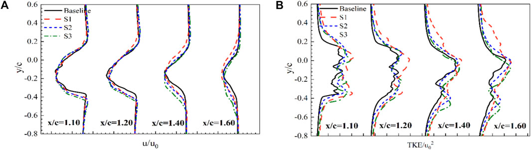
Figure 9. Wake profiles of the stalled airfoil α = 20°: (A) Velocity; (B) TKE.
3.3 Wake flow structures
3.3.1 Mean quantities
To provide a better understanding of the aerodynamic performance and wake development discussed above, we further extract and analyze the wake flow structures obtained from the simulated flow fields using IDDES. For clarity, only the typical flow fields for a flap height of h/c = 6% with α = 6° and 20° are presented in Figures 10, 11 respectively. The ensemble-averaged normalized streamwise velocity Vx/u0, and vorticity ζ0 iso-contours are plotted near the downstream of the SGF. The free stream direction is from left to right in the presented figures.
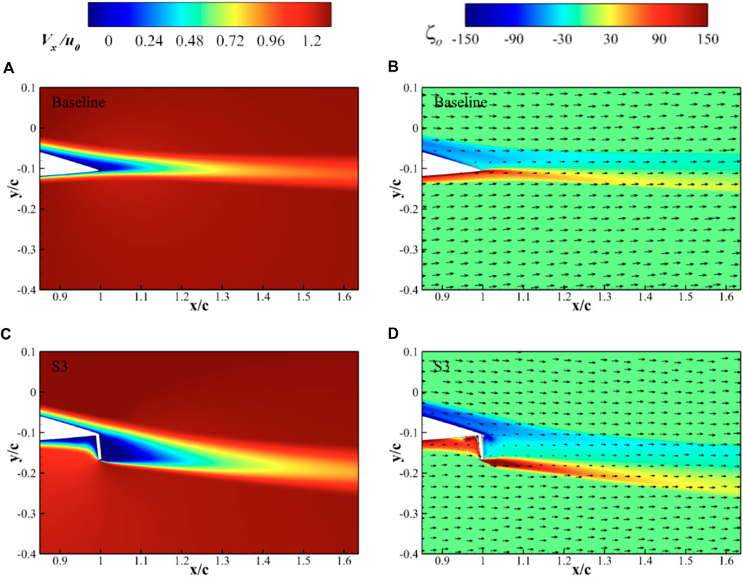
Figure 10. Impact of SGF on normalized streamwise velocity and vorticity flow fields with α = 6°. (A,B) Baseline airfoil; (C,D) S3 airfoil.
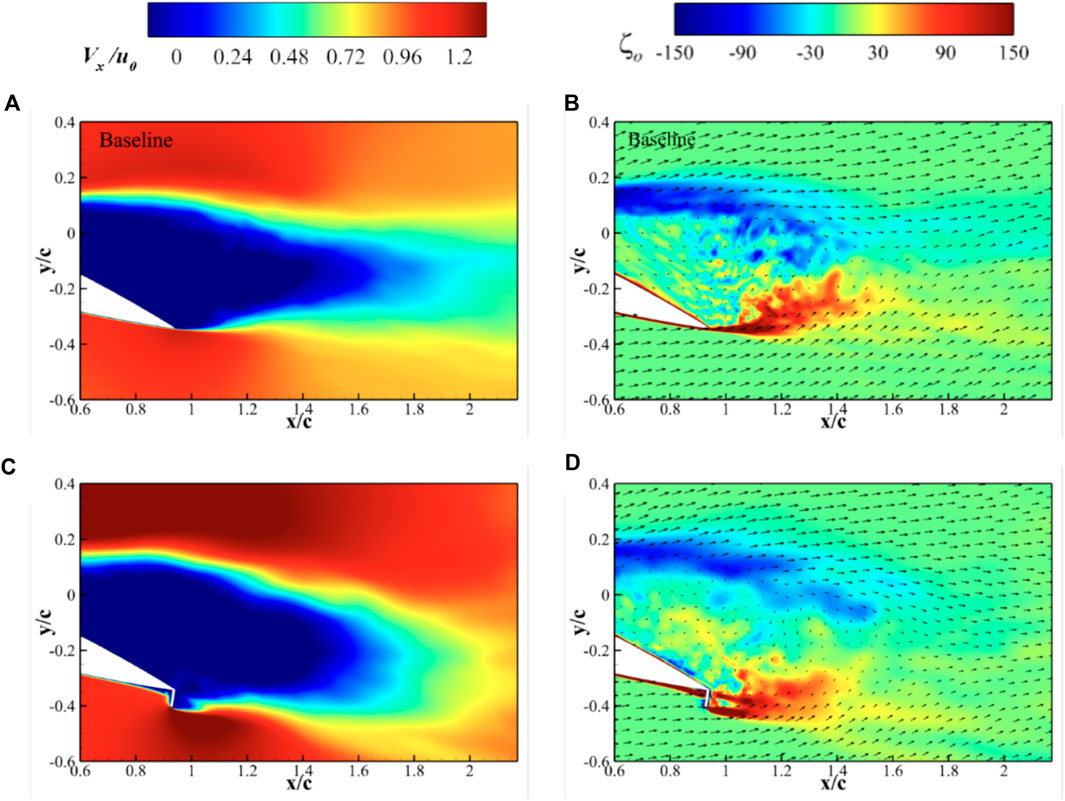
Figure 11. Impact of SGF on normalized streamwise velocity and vorticity flow fields with α = 20°. (A,B) Baseline airfoil; (C,D) S3 airfoil.
For the case with an AoA α = 6° (Figure 10), the loading is moderate and the flow over the baseline airfoil surface remains attached. The iso-contours of ζ0 indicate that the width of the near wake behind the flap with h/c = 6% is considerably widened and the maximum velocity deficit increases, compared to the baseline airfoil. It explains the increase in mean drag as shown in Figure 5B. Additionally, the wake flow direction deviates downward, indicating an increase in lift. Iso-contours of ζ0 are also included to show the vortices at the trailing edge. The negative and positive vorticities represent clockwise and anti-clockwise rotations respectively. A shear layer is clearly seen on the baseline airfoil with two concentrated vorticity streets on both sides of the airfoil. On the flapped airfoil, a small recirculated region appeared before the flap and the wake behaves as if it is behind a blunt obstacle.
Figure 11 demonstrates the wake flow structures at α = 20°, which clearly show separated flow occurring before the trailing edge on the rear suction surface of the airfoil. The flap induces extra flow deflection as well. The large separation core in the baseline airfoil is disrupted by the jet flow from the serrated flap, and the separation zone seems to be larger with lower vorticity strength. This indicates an increase in drag due to the presence of the SGF. Similar flow fields behind perforated GF were reported by Lee and Ko (2009), where the jet produced by the holes in the flap disrupted the roll-up vortex. The wake behaviour and development downstream of the trailing edge indicate that the serrated flap behaves similarly to a perforated flap or a slotted flap as used by Meyer et al. (2006).
3.3.2 Instantaneous flow fields
In addition to the mean quantities, the computational results also provide the unsteady behaviour of the near-surface flow field, particularly the structures of the flow behind the SGF. Figure 12 shows the iso-surfaces of the Q criterion (Q = 1 × 10⁵ s-2) with contours of the vorticity magnitude for the baseline and S3 airfoil at the AoAs α = 6° and 20°.
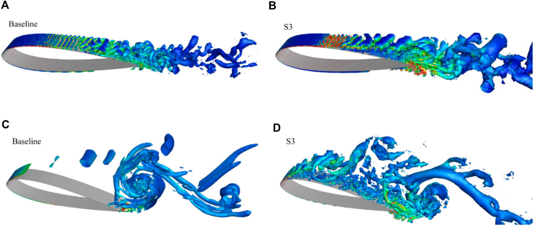
Figure 12. Iso-surfaces of the Q criterion with contours of vorticity magnitude of the baseline and S3 airfoils. (A,B) α = 6°; (C,D) α = 20°.
At the AoA α = 6°, the separation bubble on the suction side occurs at x/c = 0.4 for the baseline airfoil, while the bubble separation occurs at x/c = 0.36 for the S3 airfoil. For the baseline airfoil, the separation can be observed at x/c = 0.84 on the pressure side, while the separation on the pressure side occurs before the flap at x/c = 0.8 for the S3 airfoil, which can be attributed to the flap blockage. This separation on the pressure side of the S3 airfoil could be the primary reason for the increase of the Cp near the trailing edge, as mentioned previously. The significant two-dimensional spanwise vortex rolls appear on the suction side and the wake flow is more turbulent for the S3 airfoil, which may be the reason for the increased drag.
From the iso-surface plot at α = 20°, it can be observed that for both airfoils, the separation on the suction side occurs from the leading edge. Large blocks of vortex rolls are visible which have high vorticity intensity and far downstream ability for the baseline airfoil, while small vortices are generated on the suction side for the S3 airfoil. It seems the large separation is suppressed due to the flap at the large AoA. On the pressure side, no separation for the baseline airfoil but the separation occurs at x/c = 0.94, due to the flap structure.
Figure 13 shows the streamlines around the flap serration and iso-surfaces of the Q criterion with the velocity distribution α = 6°. A pair of counter-rotating streamwise vortices is generated behind each trough of the flapped airfoil. These induced streamwise vortices enhanced the momentum exchange and turbulent fluctuations in the downstream boundary layer. Reviewing the flow structures at both attack angles, we identify that the serrated flap generates the extra small structures with no common orientation tends, which tend to interact and dissipate more rapidly. These small vortices vanish without being convected far downstream, and complicated small-scale vortices are observed for the flapped airfoil. These features indicate that the serrated flap can break down the large-scale vortex into small vortices, which is believed to be beneficial for noise control (Oerlemans et al., 2009; Moreau and Doolan, 2013; Arce León et al., 2016).
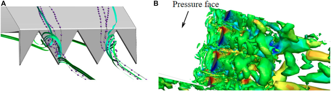
Figure 13. (A) Streamlines around the flap serration. (B) Iso-surfaces of the Q criterion with the vorticity distribution behind the flap α = 6°.
The instantaneous spanwise vorticity contours at four different time steps are presented in Figure 14 to illustrate the vortex shedding in one cycle from the baseline and S3 airfoil at α = 20°. For baseline airfoil, it can be observed that the flow separation occurs almost at the leading edge, generating an upper shear layer, whereas a higher shear layer formed on the pressure side rolls up into the airfoil wake. The roll-up of the upper shear layer without reattachment results in Kelvin-Helmoltz instabilities, which can be seen in the instantaneous vorticity contours. The vortexes roll up from the up and low shear layers alternately and fall off, exhibiting a Von-Karman-type wake characteristic. This verifies that the airfoil wake at high attack angles shows similar flow structures to those of the bluff body wake (Jacobs and Sherman, 1937). For the S3 airfoil, the same separation from the leading edge on the suction side is also observed, and the higher shear on the pressure side breaks up into irregular fine vortices through the serrations, with the fine vortices rolling up and mixing with the upper separation. The use of the SGF effectively prevents the mechanism. As a result, the vortices dissipate earlier, but the weak structures can still interact with the lower vortex roll-in formed by the SGF.
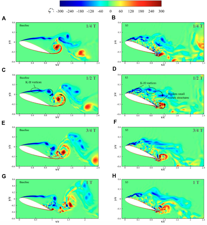
Figure 14. Contours of instantaneous spanwise vorticity magnitudes of the baseline and S3 airfoils at four different time steps. (A,B) 1/4 T; (C,D) 1/2 T; (E,F) 3/4 T; (G,H) 1 T.
4 Conclusion
A numerical study on the effect of spanwise SGF on the flow around NACA 0018 airfoil is presented at the Reynolds number of 1.6 × 10⁵. An IDDES method is utilized to simulate the unsteady flow field. The associated flow field and inherent physics are analyzed, leading to the following conclusions.
• Compared with the baseline airfoil, the airfoils with the SGF exhibit enhanced lift and drag coefficients and the maximum lift-to-drag ratio. The characteristics are similar across different heights of flaps, ranging from 2% to 6% of the chord length, which is larger than the recommendation of other researchers. The increment in the lift becomes larger as the flap height increases. Although the drag also increases within the investigated attack angle, the S3 airfoil shows the most significant improvement in lift-to-drag ratio, with a 20.3% increase, corresponding to an AoA variation from 9° to 6°. Furthermore, the stall angle is advanced 3° from 14° to 11°. In comparison with the plane flap, the SGF
• The serrations significantly affect the development of the wake deficit and the peak in the velocity deficit location compared to the baseline airfoil. At the large attack angle (α = 20°), in the range of x/c = 1.2, the wake of SGF airfoils is almost the same as the baseline due to the large separations. However, beyond the location of x/c = 1.3, the wake exhibits an obvious down-wash, resulting in an increase in the lift of the airfoil.
• The flap can affect the flow on the suction surface of the airfoil. At α = 6°, the separation is advanced and obvious two-dimensional columnar vortices are observed for the S3 airfoil, which is absent for the baseline airfoil. That might also be the reason for the increased drag caused by the flap.
• The serrations can transform the upstream columnar vortex into a pair of vortices, which wrap over both triangle sides of the serrations and rotate perpendicular to the wake flow. These vortex pairs are effective in preventing the separation mechanism in the post-stall region. The original detached post-stall flow observed in the baseline airfoil is effectively disrupted by the presence of irregular fine vortex pairs caused by the serrations in the SGF airfoils.
These findings indicate that the application of the SGF can be a viable solution to improve the aerodynamic performance of the VAWT rotor. In future studies, we plan to carry out the full simulation of the VAWT blades with the SGF installed rotating 360° around the VAWT axis to further evaluate the effect of the SGF on the VAWT power output. We can also further explore the aerodynamic characteristics of the SGF at different mounting angles, and at higher Reynolds numbers, which is crucial for large turbines, as well as in the more complex flow conditions such as the cases with small tip speed ratios and with the strong presence of dynamic stall on the blades.
Data availability statement
The original contributions presented in the study are included in the article/supplementary material, further inquiries can be directed to the corresponding author.
Author contributions
ZZ: Conceptualization, Data curation, Formal Analysis, Funding acquisition, Investigation, Methodology, Project administration, Resources, Software, Supervision, Validation, Visualization, Writing–original draft, Writing–review and editing. LC: Funding acquisition, Validation, Conceptualization, Writing–review and editing.
Funding
The author(s) declare financial support was received for the research, authorship, and/or publication of this article. This work was supported by the National Nature Science Foundation of China (Project Nos. 52276034 and 52006147).
Conflict of interest
The author declares that the research was conducted in the absence of any commercial or financial relationships that could be construed as a potential conflict of interest.
Publisher’s note
All claims expressed in this article are solely those of the authors and do not necessarily represent those of their affiliated organizations, or those of the publisher, the editors and the reviewers. Any product that may be evaluated in this article, or claim that may be made by its manufacturer, is not guaranteed or endorsed by the publisher.
Abbreviations
SGF, Serrated Gurney Flap; PGF, Plan Gurney Flap; VAWT, Vertical Axis Wind Turbine; HAWT, Horizontal Axis Wind Turbine; LES, Large Eddy Simulation; AoA, Angle of Attack; IDDES, Improved Delayed Detached Eddy Simulation; TSR, Tip Speed Ratio.
References
Aihara, A., Goude, A., and Bernhoff, H. (2020). “Les prediction for acoustic noise of airfoil at high angle of attack,” in AIAA scitech 2020 forum, 1723.
Alferez, N., Mary, I., and Lamballais, E. (2013). Study of stall development around an airfoil by means of high fidelity large eddy simulation. Flow, Turbul. Combust. 91, 623–641. doi:10.1007/s10494-013-9483-7
Anagnostopoulou, C., Kagemoto, H., Sao, K., and Mizuno, A. (2016). Concept design and dynamic analyses of a floating vertical-axis wind turbine: case study of power supply to offshore Greek islands. J. Ocean Eng. Mar. Energy 2, 85–104. doi:10.1007/s40722-015-0034-2
Arce León, C., Merino-Martínez, R., Ragni, D., Avallone, F., and Snellen, M. (2016). Boundary layer characterization and acoustic measurements of flow-aligned trailing edge serrations. Exp. fluids 57, 182–222. doi:10.1007/s00348-016-2272-z
Avallone, F., Pröbsting, S., and Ragni, D. (2016). Three-dimensional flow field over a trailing-edge serration and implications on broadband noise. Phys. Fluids 28. doi:10.1063/1.4966633
Balduzzi, F., Holst, D., Melani, P. F., Wegner, F., Nayeri, C. N., Ferrara, G., et al. (2021). Combined numerical and experimental study on the use of gurney flaps for the performance enhancement of naca0021 airfoil in static and dynamic conditions. J. Eng. Gas Turbines Power 143, 021004. doi:10.1115/1.4048908
Benim, A. C., Diederich, M., Gül, F., Oclon, P., and Taler, J. (2018). Computational and experimental investigation of the aerodynamics and aeroacoustics of a small wind turbine with quasi-3d optimization. Energy Convers. Manag. 177, 143–149. doi:10.1016/j.enconman.2018.09.042
Bianchini, A., Balduzzi, F., Di Rosa, D., and Ferrara, G. (2019). On the use of gurney flaps for the aerodynamic performance augmentation of darrieus wind turbines. Energy Convers. Manag. 184, 402–415. doi:10.1016/j.enconman.2019.01.068
Chakroun, Y., and Bangga, G. (2021). Aerodynamic characteristics of airfoil and vertical axis wind turbine employed with gurney flaps. Sustainability 13, 4284. doi:10.3390/su13084284
Gai, S., and Palfrey, R. (2003). Influence of trailing-edge flow control on airfoil performance. J. Aircr. 40, 332–337. doi:10.2514/2.3097
Garry, K., and Couthier, G. (2006). “An investigation of the effectiveness of plain and serrated gurney flaps,” in 24th AIAA applied aerodynamics conference, 3178.
Hansen, J. T., Mahak, M., and Tzanakis, I. (2021). Numerical modelling and optimization of vertical axis wind turbine pairs: a scale up approach. Renew. Energy 171, 1371–1381. doi:10.1016/j.renene.2021.03.001
Hassan, G. E., Hassan, A., and Youssef, M. E. (2014). Numerical investigation of medium range re number aerodynamics characteristics for naca0018 airfoil. CFD Lett. 6, 175–187.
Im, H.-S., and Zha, G.-C. (2014). Delayed detached eddy simulation of airfoil stall flows using high-order schemes. J. Fluids Eng. 136, 111104. doi:10.1115/1.4027813
Islam, M., Fartaj, A., and Carriveau, R. (2011). Design analysis of a smaller-capacity straight-bladed vawt with an asymmetric airfoil. Int. J. Sustain. Energy 30, 179–192. doi:10.1080/1478646x.2010.509496
Ismail, M. F., and Vijayaraghavan, K. (2015). The effects of aerofoil profile modification on a vertical axis wind turbine performance. Energy 80, 20–31. doi:10.1016/j.energy.2014.11.034
Jacobs, E. N., and Sherman, A. (1937). Airfoil section characteristics as affected by variations of the Reynolds number. NACA Tech. Rep. 586, 227–267.
Jain, S., Sitaram, N., and Krishnaswamy, S. (2015). Computational investigations on the effects of gurney flap on airfoil aerodynamics. Int. Sch. Res. notices 2015, 1–11. doi:10.1155/2015/402358
Lee, T. (2009). Aerodynamic characteristics of airfoil with perforated gurney-type flaps. J. Aircr. 46, 542–548. doi:10.2514/1.38474
Lee, T., and Ko, L. (2009). Piv investigation of flowfield behind perforated gurney-type flaps. Exp. fluids 46, 1005–1019. doi:10.1007/s00348-008-0606-1
Lei, H., Zhou, D., Bao, Y., Chen, C., Ma, N., and Han, Z. (2017a). Numerical simulations of the unsteady aerodynamics of a floating vertical axis wind turbine in surge motion. Energy 127, 1–17. doi:10.1016/j.energy.2017.03.087
Lei, H., Zhou, D., Bao, Y., Li, Y., and Han, Z. (2017b). Three-dimensional improved delayed detached eddy simulation of a two-bladed vertical axis wind turbine. Energy Convers. Manag. 133, 235–248. doi:10.1016/j.enconman.2016.11.067
Li, Y., Wang, J., Tan, G., and Zhang, P. (2002). Effects of gurney flaps on the lift enhancement of a cropped nonslender delta wing. Exp. fluids 32, 99–105. doi:10.1007/s003480200010
Liebeck, R. H. (1978). Design of subsonic airfoils for high lift. J. Aircr. 15, 547–561. doi:10.2514/3.58406
Menter, F. R. (1994). Two-equation eddy-viscosity turbulence models for engineering applications. AIAA J. 32, 1598–1605. doi:10.2514/3.12149
Meyer, R., Hage, W., Bechert, D., Schatz, M., and Thiele, F. (2006). Drag reduction on gurney flaps by three-dimensional modifications. J. Aircr. 43, 132–140. doi:10.2514/1.14294
Meyer, R., Hage, W., Bechert, D. W., Schatz, M., Knacke, T., and Thiele, F. (2007). Separation control by self-activated movable flaps. AIAA J. 45, 191–199. doi:10.2514/1.23507
Moreau, D. J., and Doolan, C. J. (2013). Noise-reduction mechanism of a flat-plate serrated trailing edge. AIAA J. 51, 2513–2522. doi:10.2514/1.j052436
Neuhart, D. H. (1988). A water tunnel study of Gurney flaps, vol. 4071. Scientific and Technical Memorandum: National Aeronautics and Space Administration.
Ni, L., Miao, W., Li, C., and Liu, Q. (2021). Impacts of gurney flap and solidity on the aerodynamic performance of vertical axis wind turbines in array configurations. Energy 215, 118915. doi:10.1016/j.energy.2020.118915
Oerlemans, S., Fisher, M., Maeder, T., and Kögler, K. (2009). Reduction of wind turbine noise using optimized airfoils and trailing-edge serrations. AIAA J. 47, 1470–1481. doi:10.2514/1.38888
Rolin, V. F., and Porté-Agel, F. (2018). Experimental investigation of vertical-axis wind-turbine wakes in boundary layer flow. Renew. energy 118, 1–13. doi:10.1016/j.renene.2017.10.105
Shur, M., Spalart, P., Strelets, M., and Travin, A. (1999). “Detached-eddy simulation of an airfoil at high angle of attack,” in Engineering turbulence modelling and experiments 4 (Elsevier), 669–678.
Shur, M. L., Spalart, P. R., Strelets, M. K., and Travin, A. K. (2008). A hybrid rans-les approach with delayed-des and wall-modelled les capabilities. Int. J. heat fluid flow 29, 1638–1649. doi:10.1016/j.ijheatfluidflow.2008.07.001
Spalart, P., Jou, W., Strelets, M., and Allmaras, S. (1997). “Comments on the feasibility of les for wings, and on a hybrid rans/les approach,” in First AFORS int. Conf. On direct numerical simulation and large eddy simulation.
Spalart, P. R. (2009). Detached-eddy simulation. Annu. Rev. fluid Mech. 41, 181–202. doi:10.1146/annurev.fluid.010908.165130
Timmer, W. (2008). Two-dimensional low-Reynolds number wind tunnel results for airfoil naca 0018. Wind Eng. 32, 525–537. doi:10.1260/030952408787548848
Traub, L. W., and Chandrashekar, S. M. (2016). Experimental study on the effects of wing sweep on gurney flap performance. Aerosp. Sci. Technol. 55, 57–63. doi:10.1016/j.ast.2016.05.015
Turner, J. M., and Kim, J. W. (2020). Effect of spanwise domain size on direct numerical simulations of airfoil noise during flow separation and stall. Phys. Fluids 32. doi:10.1063/5.0009664
Van Dam, C., Yen, D., and Vijgen, P. (1999). Gurney flap experiments on airfoil and wings. J. Aircr. 36, 484–486. doi:10.2514/2.2461
Wang, G., Zhang, L., and Shen, W. Z. (2018). Les simulation and experimental validation of the unsteady aerodynamics of blunt wind turbine airfoils. Energy 158, 911–923. doi:10.1016/j.energy.2018.06.093
Wilbur, M. L., Mistry, M. P., Lorber, P. F., Blackwell Jr, R., Barbarino, S., Lawrence, T. H., et al. (2018). Rotary wings morphing technologies: state of the art and perspectives. Morphing Wing Technol., 759–797. doi:10.1016/b978-0-08-100964-2.00024-1
Xie, Y., Jiang, W., Lu, K., and Zhang, D. (2016). Numerical investigation into energy extraction of flapping airfoil with gurney flaps. Energy 109, 694–702. doi:10.1016/j.energy.2016.05.039
Yan, Y., Avital, E., Williams, J., and Cui, J. (2020). Performance improvements for a vertical axis wind turbine by means of gurney flap. J. Fluids Eng. 142, 021205. doi:10.1115/1.4044995
Yang, Y., Li, C., Zhang, W., Guo, X., and Yuan, Q. (2017). Investigation on aerodynamics and active flow control of a vertical axis wind turbine with flapped airfoil. J. Mech. Sci. Technol. 31, 1645–1655. doi:10.1007/s12206-017-0312-0
Ye, X., Hu, J., Zheng, N., and Li, C. (2023). Numerical study on aerodynamic performance and noise of wind turbine airfoils with serrated gurney flap. Energy 262, 125574. doi:10.1016/j.energy.2022.125574
Zhang, Y., Avallone, F., and Watson, S. (2022). Wind turbine blade trailing edge crack detection based on airfoil aerodynamic noise: an experimental study. Appl. Acoust. 191, 108668. doi:10.1016/j.apacoust.2022.108668
Keywords: serrated gurney flap, airfoil aerodynamics, airfoil wake, passive flow control, vertical axis wind turbine
Citation: Zheng Z and Chen L (2024) Aerodynamic performance and wake development of NACA 0018 airfoil with serrated gurney flaps. Front. Energy Res. 12:1363402. doi: 10.3389/fenrg.2024.1363402
Received: 30 December 2023; Accepted: 27 March 2024;
Published: 03 May 2024.
Edited by:
Alessandro Bianchini, University of Florence, ItalyReviewed by:
Pier Francesco Melani, Università di Firenze, ItalyChristian Nayeri, Technical University of Berlin, Germany
Galih Bangga, DNV GL, United Kingdom
Copyright © 2024 Zheng and Chen. This is an open-access article distributed under the terms of the Creative Commons Attribution License (CC BY). The use, distribution or reproduction in other forums is permitted, provided the original author(s) and the copyright owner(s) are credited and that the original publication in this journal is cited, in accordance with accepted academic practice. No use, distribution or reproduction is permitted which does not comply with these terms.
*Correspondence: Zhehui Zheng, 15201924045@163.com