Effect of the impeller blade outlet setting angle on the performance of the helical axial-flow multiphase pump
 Jiaqiong Wang1,2
  Chen Hu
 Ling Bai
 Ramesh Agarwal
 Ling Zhou
- 1National Research Center of Pumps, Jiangsu University, Zhenjiang, China
- 2Wenling Fluid Machinery Technology Institute of Jiangsu University, Zhenjiang, China
- 3Department of Mechanical Engineering and Materials Science, Washington University in St. Louis, St. Louis, MO, United States
As one of the core pieces of equipment in the multiphase mixing system, the helical axial-flow multiphase pump plays a vital role in the process of offshore oil extraction. In order to explore the influence of the impeller blade outlet setting angle on the internal flow of the helical axial-flow multiphase pump, this paper increases the outlet setting angle of the flow surface by −3°, −1.5°, and 1.5°, respectively, based on the original multiphase pump. It calculates the flow characteristics of the impeller with four different outlet setting angles (including the original impeller) under the design condition with different inlet gas volume fractions (GVFs = 0, 10%, 30%, 50%, and 70%) by adopting the Euler–Euler non-homogeneous flow model and SST k-ω turbulence model. Furthermore, it compares its external characteristic curve and the internal pressure, velocity, gas distribution, and other rules of change of the impeller and guide vane under higher inlet GVF conditions (50%). The results show that in the pure water state, increasing the outlet setting angle appropriately can enhance both the pressure pressurization capability and efficiency of the helical axial-flow multiphase pump; the pressure pressurization capability and efficiency of each scheme decrease with an increase in inlet GVF, and at 50%–70% inlet GVF, the option of increasing the outlet setting angle by −1.5° is better; as the blade outlet setting angle decreases, the axial cross-sectional pressure after gas–liquid mixing increases, the overall velocity distribution is more uniform, and the vortex formed due to the counter-pressure flow in the secondary guide vane is reduced; the accumulation of gas phase on the backside of the impeller and guide vanes improves, leading to a reduction in flow losses.
1 Introduction
With the increasing exploitation of land-based fossil energy, attention is gradually shifting toward the seabed, which harbors abundant oil and gas resources (Dai et al., 2023; Qiu et al., 2023). Helical axial-flow multiphase pumps, as the core equipment for offshore oil and gas extraction, have the advantages of a simple and compact structure, excellent corrosion resistance (Zhang et al., 2020; Yang et al., 2024), and high efficiency in conveying multiphase fluids, even under high gas content. The impeller is the main booster unit of the helical axial-flow multiphase pump; its structural quality directly affects the overall pumping performance of the pumping unit. Hence, investigating the impeller’s structure holds paramount significance (Han et al., 2022; Li et al., 2023).
In recent years, numerous scholars have conducted analyses on the impacts of various impeller structural parameters on the internal flow of helical axial-flow multiphase pumps through numerical simulations. Han et al. (2020) introduced the impeller blade thickness ratio coefficient ξ and investigated the effect of the thickness ratio coefficient on the mixing and conveying characteristics of the helical axial-flow multiphase pump. The results showed that when the hub thickness was kept constant, reducing ξ, the head coefficient and efficiency increased, and the degree of gas aggregation was reduced. The performance of the helical axial-flow multiphase pump can be improved by adjusting ξ, which delays the gas collection inside the impeller channel to the trailing edge of the vane. Kim et al. (2019) introduced a coefficient representing the volume occupied by the blade within the flow channel and conducted a corresponding investigation on blade thickness. They identified the optimal coefficient for blade proportionality, established the correlation between flow rate and proportionality coefficient, and concluded that the pressurization capacity is directly proportional to the proportionality coefficient. Zhang et al. (2012) explored the impact of incorporating various impeller structures, including short vanes, T-type vanes, and vane openings, on the internal flow characteristics of helical axial-flow multiphase pumps. They observed that these distinct impeller structures can effectively disperse air masses and suppress gas–liquid separation, leading to a more uniform distribution of internal flow. Yao et al. (2021) carried out numerical simulations of a two-stage helical axial-flow multiphase pump to investigate the effect of the number of impeller blades and the wrap angle on the external characteristics of the pump at 5%–30% inlet GVF and obtained the conclusion that the head and efficiency reached their maximum value when the number of blades was 3 and the wrap angle was 215°. Furthermore, certain scholars have opted for diverse structural parameters to optimize the impeller design of helical axial-flow multiphase pumps. Liu et al. (2018) investigated the effect of the variable tilt setting angle of the impeller along the axial plane and the variation of hub and shroud coefficients on the internal flow of the helical axial-flow multiphase pump through orthogonal experiments and found that the variation of shroud setting angle at 10% inlet GVF had the greatest effect on the pressure rise. The optimal values of the parameters were determined through orthogonal analysis by estimating the effect of each factor on the pressure enhancement, and the optimized pressure distribution in the pump was more uniform compared to the original model. Suh et al. (2017a); (2017b) successively studied single-stage and multi-stage helical axial-flow multiphase pumps, taking the impeller’s hub inlet angle, shroud inlet angle, and shroud outlet angle and the guide vane’s hub inlet angle and shroud inlet angle as the optimization parameters. With the objective of maximizing efficiency and pressurizing capacity, the samples were selected by the central composite method, and the response surface method was used as the approximation model. The NSGA-II algorithm was used to obtain the global optimal solution of the approximate model, and the selected optimal model had better hydrodynamic performance than the base model. The reasons were investigated through the internal flow field analysis. Zhang et al. (2011); Zhang et al. (2017) developed a multi-objective optimization method by combining an artificial neural network with the NSGA-II algorithm. The main parameters affecting the performance of the blades, such as the impeller’s inlet angle, outlet angle, hub semi-cone angle, and inlet hub ratio of the helical axial-flow multiphase pump, were optimized. The results showed that the area occupied by the gas on the blade surface of the optimized impeller was significantly reduced and that the performance of the compression unit was improved.
In conclusion, recent domestic and international research on structural modifications and internal flow dynamics of helical axial-flow multiphase pump impellers has yielded significant progress. However, analysis regarding the high gas content remains limited. Notably, the impeller blade setting outlet angle, recognized as a parameter exerting substantial influence on helical axial-flow multiphase pump performance (Kim et al., 2015; Zhou et al., 2022), lacks dedicated literature exploration. Based on the current status of the research, this paper takes the impeller blade setting outlet angle of the helical axial-flow multiphase pump as the object of the study to analyze its effect on the internal flow characteristics of a three-stage multiphase pump under different inlet GVF values and provides a reference basis for the design and optimization of the subsequent helical axial-flow multiphase pump.
2 Research objects and numerical calculation methods
2.1 Helical axial-flow multiphase pump model and geometrical parameters
Taking the three-stage spiral axial helical axial-flow multiphase pump as the calculation domain in order to reduce the influence of the boundary conditions on the calculation accuracy, the inlet and outlet are appropriately extended, and the length of the inlet and outlet sections is 5 times the impeller inlet diameter. The calculation domain consists of the inlet extension section, the outlet extension section, the three-stage impeller, and the three-stage guide vane, and the fluid domain model is shown in Figure 1. The main structural parameters of the impeller guide vane dimensions are shown in Table 1.

Figure 1. Geometric model of a three-stage helical axial-flow multiphase pump.
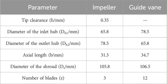
Table 1. Main performance parameters of the helical axial-flow multiphase pump.
2.2 Scheme design
On the basis of the original model, to ensure that the impeller blade wrap angle, blade inlet setting angle, blade thickness, and other geometry parameters of the helical axial-flow multiphase pump are under the same conditions, only the impeller blade outlet setting angle is changed; in CFturbo, the impeller blade outlet setting angle of the different flow surfaces is increased by −3°, −1.5°, and 1.5° at intervals of 1.5° to change the blade outlet setting angle. The aim of the design is to get four kinds of schemes. The flow of model generation for different schemes is shown in Figure 2.
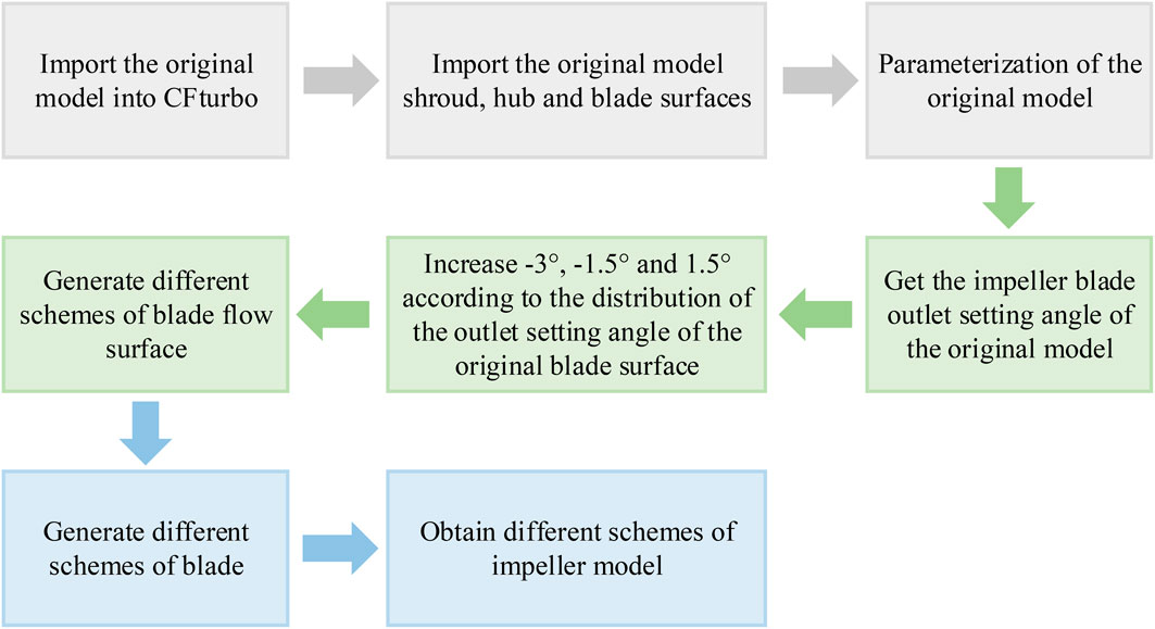
Figure 2. Flowchart of model generation for different schemes.
The comparative 3D models of the blade, generated based on the aforementioned procedures, are depicted in Figure 3.

Figure 3. Blade model contrast of different schemes.
2.3 Numerical methods and boundary conditions
2.3.1 Governing equations
The multiphase flow model used in this paper is the Euler–Euler non-homogeneous phase flow model (Hang et al., 2022; Sun et al., 2024). The gas–liquid two-phase medium is regarded as two continuous single-phase flows, solving the equations of the gas and liquid phases and considering the interaction between the two phases, which is more in line with the actual flow of the fluid. The incompressible fluid continuity and momentum equations are expressed as follows (Zhang et al., 2018a; Zhang et al., 2018b):
The continuity equation is
The momentum equation is
where the scale k = l or g denotes the liquid or gas phase, respectively, αk denotes the volume fraction αl + αk = 1 of the gas or liquid phase, ρk denotes the density of the gas–liquid or liquid phase, Mk denotes the inter-phase force, fk denotes the mass force, p denotes the pressure, Uk denotes the velocity, and τk denotes the viscous stress tensor of the fluid viscosity and the turbulent viscosity.
2.3.2 Boundary condition setting
3D Reynolds time-averaged Navier–Stokes (NS) equations are solved using the SST k-ω turbulence model in commercial CFD software ANSYS CFX 2020 R2 (Guo et al., 2023; Tang et al., 2024). The gas–liquid two-phase medium is pure water (water) and air (air at 25°C). Pure water is set as a continuous phase, and air is set as a discrete phase, and they are incompressible. The inlet section of the gas–liquid two-phase flow velocity distribution of the gas–liquid two-phase flow velocity is uniform and equal, and the model wall boundaries are non-slip solid-wall boundary conditions. The specific numerical calculations of the boundary conditions and parameter settings are given in Table 2.
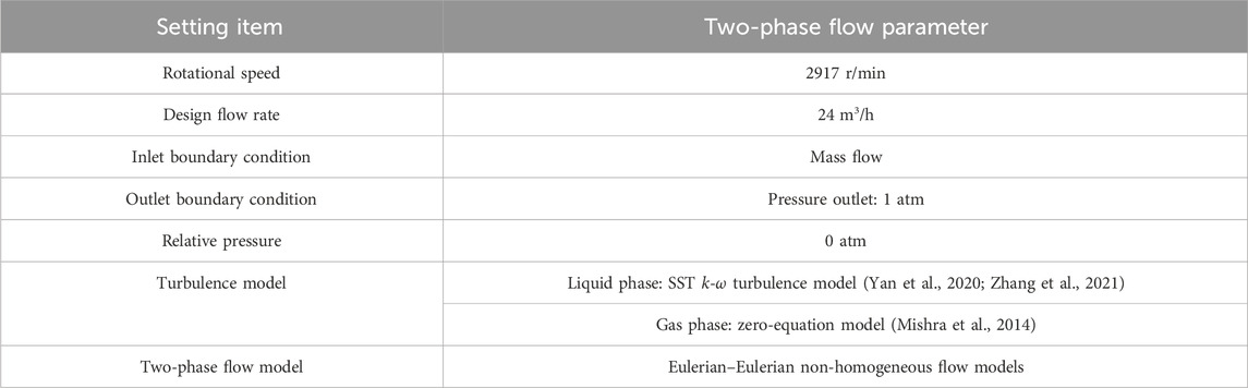
Table 2. Numerical simulation setting.
2.4 Grid independence test
In this paper, TurboGrid 2020 R2 is used to perform six sets of structural meshing with different numbers of structural meshes for the hydraulic model, and numerical calculations are carried out for each of them at the design flow rate. Figure 4 shows the pressurization capacity and efficiency of the three-stage helical axial-flow multiphase pump calculated under different grid numbers, and it is found that when the overall number of grids is more than 10,143,540, the booster capacity of the helical axial-flow multiphase pump varies less than 0.152%, and the efficiency varies less than 0.015%, so the simulation chooses 10,143,540 grids for the simulation to ensure the irrelevance of the grids. Figure 5 shows the grid division of the impeller and guide vane at each level, and the number of grids for inlet extension, impeller, guide vane, and outlet extension is 1,062,000; 1,480,584; 1,192,596; and 1,062,000, respectively.
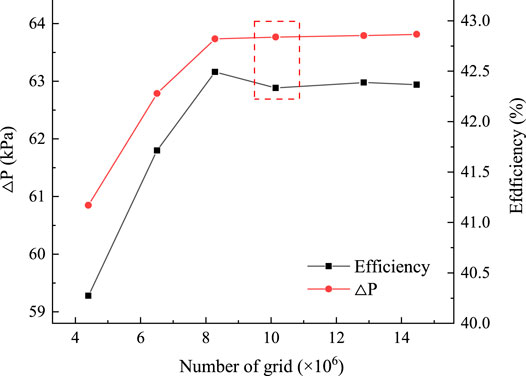
Figure 4. Grid independence verification.
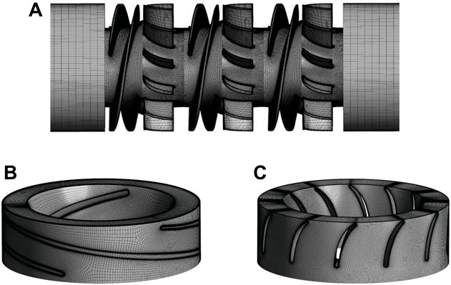
Figure 5. Three-stage helical axial-flow multiphase pump structure grid diagram. (A) Computational domain grid. (B) Impeller water body grid. (C) Guide vane water body grid.
3 Analysis of calculation results
This paper mainly focuses on four three-stage spiral axial oil and gas helical axial-flow multiphase pump model schemes. Simulation calculations are conducted under operating conditions with a design flow rate of 24 m3/h and varying inlet GVF values of 0%, 10%, 30%, 50%, and 70%, and the external characteristic curve of the three-stage helical axial-flow multiphase pumps under different inlet GVF values, along with the axial pressure distribution curve inside the impeller and guide vanes at higher inlet GVF (50%), pressure cloud, velocity cloud, velocity line graph, and gas distribution cloud diagram were considered for comparative analysis.
3.1 External characteristics analysis
From the basic equation (Zhang et al., 2018b) for the theoretical head of an axial flow pump in the case of pure water, the pressurization formula is given as
where u is the impeller circumferential velocity, m/s; ρl is the density of pure water, kg/m3; vu2 is the circumferential component of the absolute velocity at the impeller outlet, m/s; and vu1 is the circumferential component of the absolute velocity at the impeller inlet, m/s.
Assuming that the air bubbles in the helical axial-flow multiphase pump are uniformly distributed and the velocity of the gas–liquid two-phases is the same, the following equations can be obtained (Ma et al., 2019):
where ρ is the gas–liquid mixed density, kg/m3; ρg is the gas density, kg/m3; Qg is the gas flow rate, m3/s; Ql is the liquid flow rate, m3/s; ΔPg is the sum of pressure loss in the three-stage guide vane, kPa; Pf,1 is the total pressure of inlet of the first-stage guide vane, kPa; Pf,2 is the total pressure of outlet of the first-stage guide vane, kPa; Ps,1 is the total pressure of inlet of the second-stage guide vane, kPa; Ps,2 is the total pressure of outlet of the second-stage guide vane, kPa; and Pl,1 is the total pressure of inlet of the last-stage guide vane, kPa; Pl,2 is the total pressure at the outlet of the last-stage guide vane, kPa; ΔPt is the total pressure increase in the three-stage helical axial-flow multiphase pump, which is used to characterize pump pressurization capacity, kPa; Pl is the inlet pressure of the three-stage helical axial-flow multiphase pump, kPa; P2 is the inlet pressure of the three-stage helical axial-flow multiphase pump, kPa; η is the efficiency of the helical axial-flow multiphase pump; Q is the total flow rate of gas–liquid, m3/s; n is the rotational speed of the helical axial-flow multiphase pump, r/min; and M is the torque of the helical axial-flow multiphase pump, N·m.
As shown in Figure 6, in the pure water state, as the impeller outlet placement angle β2 increases, its pressure-boosting capacity and shaft power will gradually increase. This is because with the impeller outlet placement angle increasing, the circumferential velocity u is unchanged, the axial component of the absolute velocity vm2 is unchanged, and the absolute velocity v increases, resulting in an increase in the circumferential component of the absolute velocity vu2 and pressure-boosting capacity, which is consistent with the trend of changes in Eqs 3–1. The shaft power increases, and efficiency first increases and then decreases with the increase in the impeller outlet placement angle. However, the difference in efficiency between the different schemes is not significant, with M2 being the most efficient and M1 being the least efficient, with a difference of 1.07%.
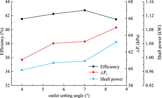
Figure 6. Influence of different blade outlet setting angles on pump external characteristics under the pure water condition.
Figure 7 shows the relationship curve of pressure loss in the guide vane of the helical axial-flow multiphase pump with the variation in inlet GVFs under different schemes, calculated from Eqs 3–3. From the figure, it can be seen that the pressure loss in the guide vane of different schemes first grows and then reduces with the increase in inlet GVF values. The pressure loss in the guide vane is the most in the case of 30% inlet GVF, and the pressure loss in the guide vane is the least in the case of 70% inlet GVF. That is, the larger the impeller outlet setting angle, the greater the degree of distortion of the impeller blades. At this time, this distortion aggravates gas–liquid separation, which is perpendicular to the direction of the relative flow rate. So, there is an increase in flow loss within the guide vanes due to the media flowing into them.
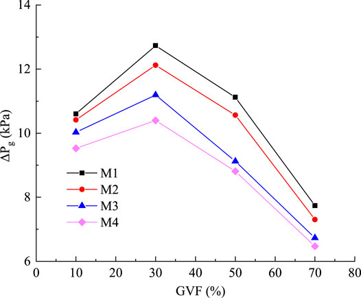
Figure 7. Relation curve of pressure loss in three guide vanes with inlet GVF changes under different schemes.
Figure 8A shows the relationship curve between the pressurization capacity and the variation in inlet GVFs. As can be seen from the figure, the pressurization capacity of the different schemes decreases with an increase in inlet GVF values. At inlet GVF ranging from 10% to 30%, M4 has the strongest pressurization capacity and M1 has the weakest pressurization capacity. This phenomenon is attributed to the significant distortion of the impeller blades in M1, leading to severe gas–liquid separation and increased energy loss within the multiphase pump, consequently resulting in a pressure drop. At 10% inlet GVF, the pressurization capacity of the M3 and M4 models is significantly higher than that of M1 and M2. This indicates that at low inlet GVF values, the pressurization capacity is maximized when the outlet setting angle of the mixed-flow pump tends toward lower values. With an increase in inlet GVF values, the pressure pressurization capacity of helical axial-flow multiphase pumps under the four schemes decreases. At inlet GVF ranging from 50% to 70%, the pressurization capacity of M3 is maximized, exceeding that of M2 by 1.06 kPa. Figure 8B presents the relationship curve between efficiency and inlet GVF variation. It is observed from the figure that the efficiency of the multiphase pump decreases with an increase in inlet GVF values across different schemes. Among them, M2 exhibits the highest efficiency, while M4 demonstrates the lowest. Notably, at gas contents ranging from 50% to 70%, the efficiency difference between M2 and M3 is merely 0.46%. Therefore, selecting the M3 model is preferable for operating at a higher inlet GVF value.
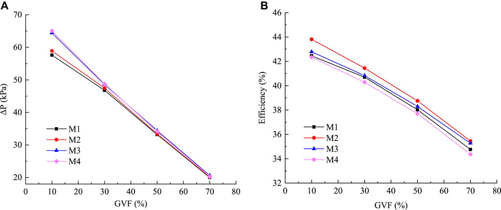
Figure 8. Relationship curves of the pressurization capacity and efficiency of the helical axial-flow multiphase pump with the inlet GVF change under different schemes. (A) Pressurization capacity curve. (B) Efficiency curve.
3.2 Flow filed analysis
3.2.1 Axial pressure curves
Figure 9 shows the curves of axial pressure variation of the helical axial-flow multiphase pump under different scenarios of 50% inlet GVF. As can be seen from the figure, the medium under each scheme continues to increase across all levels of impeller pressure, the impeller’s pressurization effect is significant, and the pressure inside the guide vane does not change much. However, along the axial direction, there will be a slight decline at first and then an increase in the tendency. This is due to the gas inside the guide vane siltation, resulting in a decrease in the average pressure of the cross-section in this region. Figure 14 shows the gas distribution.
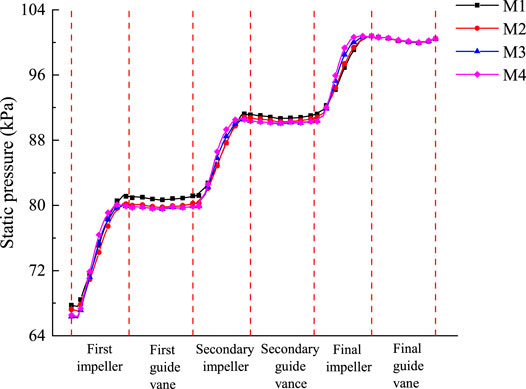
Figure 9. Axial pressure curve of the helical axial-flow multiphase pump under different schemes.
The initial pressure inside the first-stage impeller of M3 is the lowest, M1 is the highest, and the pressure of each scheme tends to be the same inside the guide vane of the last stage, which means that the M3 scheme has the most pressurization from the first-stage impeller to the last-stage guide vane, and the M1 scheme has the least pressurization. By comparing the pressurization capacity of the different schemes within the impeller guide vanes at all levels, it can be seen that M4 has the greatest rate of pressure change within the impeller in the axial direction; that is, the rate of pressurization within the impeller is the fastest. After passing through the first impeller, the pressurization capacity of M1 is high compared to the other schemes. On the other hand, after passing through the secondary and final impellers, the pressurization capacity of M3 and M4 is significantly higher and exceeds that of M1 and M2. It can be seen that in order to enhance the pump boosting capacity, the first impeller outlet angle of placement can be increased appropriately, and the secondary and final impeller outlet setting angles should be reduced appropriately.
3.2.2 Pressure distribution
As can be seen from Figure 9, the difference between the initial pressure of the medium entering the first stage and the secondary impeller under different schemes is larger relative to that of the last-stage impeller, and the trend of pressure change within each compression stage is consistent. So, in order to more accurately compare the pressurization capacity under different schemes, the pressure distribution of the guide vane of the last-stage impeller will be selected for comparison. As shown in Figure 10, for the pressure distribution of the working surface of the blade of the last-stage impeller under different schemes, M1 to M4, the pressurization capacity of the last-stage impeller is enhanced with a decrease in the outlet angle of placement, which is consistent with the results shown in Figure 9. It is because the gas–liquid mixing in the impeller and guide vane will be more uniform with the decrease in the outlet angle of the impeller (as shown in Figures 14 and 15), which reduces the energy loss inside the impeller and makes its pressurization capacity stronger. Figure 11 shows the axial pressure distribution diagram of the final-stage guide vane. Although the pressure inside the final stage guide vane tends to be the same as that obtained in Figure 9 under different schemes, significant changes can still be found after further comparison, and it can be seen that there is a large low-pressure zone area in the middle and rear parts of the final-stage guide vane. It is due to the rotation of the impeller that the lower density of gas is mainly distributed in the hub of the impeller, while the higher density of water is distributed in the shroud. As the medium enters the guide vane, inertia keeps the gas–liquid inlet at the guide vane in its original state, resulting in higher pressure at the guide vane inlet shroud and lower pressure at the hub. Due to the lower density of the gas phase from the hub to the shroud and the higher density of water from the shroud to the hub, there is gas–liquid two-phase remixing, resulting in increased pressure at the back part of the guide vane compared to the pressure at the guide vane inlet hub. In addition, from M1 to M4, it is evident that the lowpressure area gradually decreases, as the blade outlet angle of placement decreases, a more homogeneous gas–liquid two-phase mixing after entering the guide vane, resulting in the axial crosssection pressure increases.
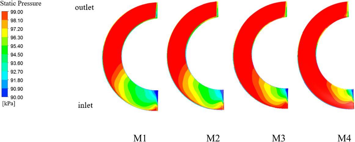
Figure 10. Static pressure distribution of the final stage impeller blade working face under different schemes.

Figure 11. Axial static pressure distribution of the final guide vane under different schemes.
3.3 Velocity distribution
3.3.1 Absolute velocity distribution
Since the velocity distributions within each compression stage are roughly similar under the same scheme, the secondary impeller, which is more clearly contrasted under different schemes, is selected for discussion. Figure 12 shows the absolute velocity distribution of water at 0.5 span in the secondary impeller and guide vane of the helical axial-flow multiphase pump for different schemes of 50% inlet GVF. As can be seen from the figure, the velocity of the medium in the impeller is greater than its velocity in the guide vanes for the same scheme. The high-speed zone is mainly concentrated in the impeller blade working surface, the back of the import and export, the guide vane blade working surface, and the back of the inlet area. Due to the initial velocity of the medium, after entering the impeller, part of it will come into first contact with the back of the impeller inlet, resulting in a higher speed at the back of the impeller blade. After the rotation of the impeller, the medium in the impeller work surface and at the exit attains a greater speed; the medium flows out of the impeller at high speeds, relying on inertial impact to reach the back of the guide vane blade front, and then flows along the work surface of the guide vane. This results in higher speeds at back of the guide vane blades at the inlet compared to the guide vane work surface. Due to the higher speed of the media closer to the impeller working surface, the corresponding inflow of the guide vane blade working surface of the high-speed area is greater than the guide vane within the other blade working surface of the high-speed zone area. The back of the impeller and guide vane under different schemes have a large area of low-velocity zone, which is due to the large amount of gas sludge in this area causing blockage. By comparing the schemes, it is found that from M1 to M3, the velocity inside the impeller decreases significantly, which is in line with the above analysis, and the area of the low-speed zone inside the secondary guide vane decreases gradually, so it can be known that appropriately decreasing the impeller outlet placement angle can make the velocity distribution inside the guide vane more uniform.
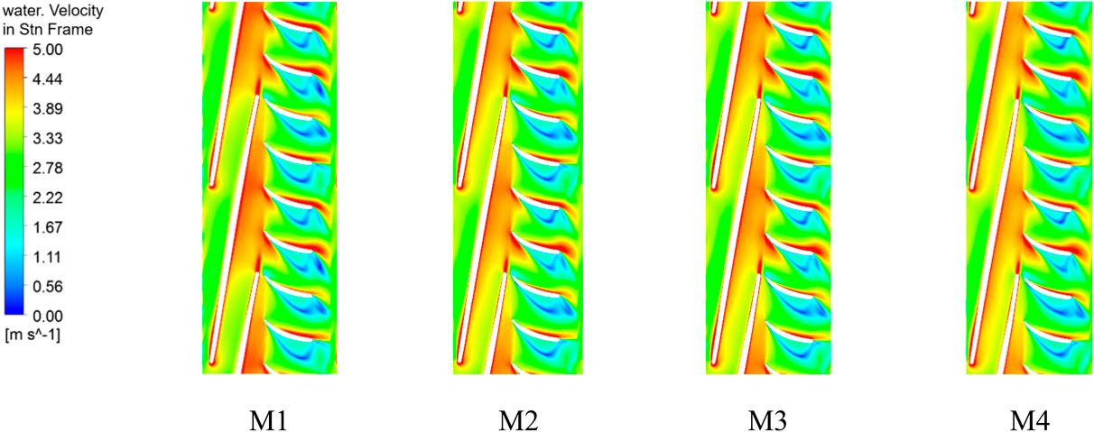
Figure 12. Absolute velocity distribution in the secondary impeller and guide vane at 0.5 span under different schemes (part).
3.3.2 Velocity streamlines
In order to further compare the distribution pattern of the area in the low-velocity region from M1 to M4, a portion of the flow line within the secondary guide vane will be selected for analysis. As shown in Figure 13, the distribution of flow lines in the secondary guide vane of the helical axial-flow multiphase pump under different scenarios of 50% inlet GVF shows that there are a large number of vortices inside the guide vane; the vortex exists in the same location as the low-speed zone, which exists at the back of the guide vane; and the vortex exists at the back of the guide vane. This is because the medium enters the guide vane due to the accumulation of air masses in the guide vane and the formation of a low-pressure zone caused by the fluid flow of counter-pressure, and the medium’s speed is not enough to fight against the counter-pressure gradient, resulting in the formation of a vortex, which reduces the performance of the helical axial-flow multiphase pump.
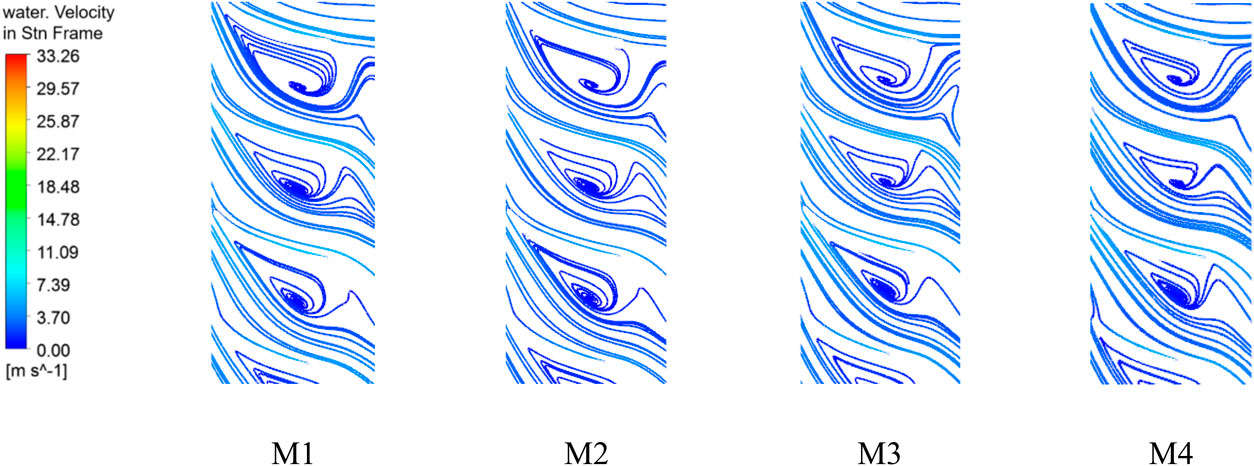
Figure 13. Distribution of flow line in the secondary guide vane at 0.5 span under different schemes (part).
The vortex inside the secondary guide vane from M1 to M3 is obviously reduced, and the distribution of the vortex between M3 and M4 is similar, which can be more clearly proved by the reduction of the area of the low-speed zone. This also coincides with the law that the smaller the outlet setting angle is, the smaller the loss inside the guide vane is obtained from the above under the same inlet GVF. It can be seen that an appropriate increase in the outlet setting angle of the impeller can reduce the vortex inside the guide vane, thus reducing the hydraulic loss inside the guide vane.
3.4 Gas distributions
As shown in Figure 14, the gas distribution diagram in the impeller and guide vane at 0.5 span under different schemes of 50% inlet GVF reveals that in the impeller, as the pressure at the working surface of the impeller is greater than the pressure at its back, the gas mostly gathers at the back of the blade. The gas volume fraction at the outlet on the back of the blade from M1 to M4 gradually decreases because the gas phase inside the impeller will be transported due to an increase in the blade outlet setting angle. This weakens the impeller’s control of the medium and intensifies gas–liquid separation in the circumferential direction, causing more of the gas phase to gather at the outlet toward the back of the blade. Therefore, reducing the outlet setting angle will improve the gathering of the gas at the back of the impeller blade, thus reducing the flow loss in the impeller.
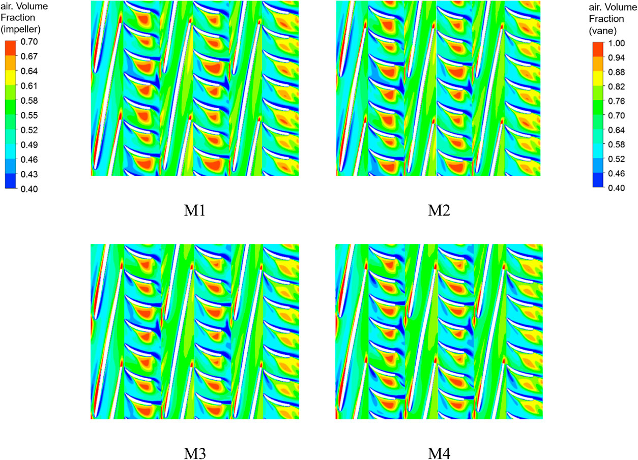
Figure 14. Gas distribution diagram in the impeller and guide vane at 0.5 span under different schemes.
In the guide vane, the gas is mainly concentrated in the back of the guide vane blades; the medium from the last stage of the guide vane outflows no longer into the next level of impeller pressurization, and gas–liquid mixing will outflow gently, so the volume fraction of the gas in the last stage of the back of the guide vane blades is relatively small compared to the first and second stages. By comparing the different schemes, it can be obtained that from M1 to M4, the volume of gas gathered at the back of the guide vane decreases, and the red area with a large gas volume fraction in the final guide vane gradually disappears. The improvement in the gas gathering situation in the secondary guide vane is more obvious compared to the secondary guide vane, so the appropriate reduction of the outlet setting angle can make gas–liquid mixing in the helical axial-flow multiphase pump more uniform, and gas–liquid separation is not easy to occur.
4 Conclusion
The results of the numerical simulation of a three-stage spiral axial flow helical axial-flow multiphase pump under different inlet GVF and different outlet setting angles are analyzed, and the following conclusions are drawn:
1) In a state of pure water, appropriately increasing the outlet setting angle of the impeller blade can elevate the absolute velocity at the outlet, thereby enhancing the boosting capacity and efficiency of the helical axial-flow multiphase pump. However, excessively increasing the outlet setting angle can lead to a decline in its efficiency.
2) At different inlet GVF values, as the blade outlet setting angle increases, the degree of impeller blade distortion increases, and the direction perpendicular to the relative flow velocity of gas–liquid separation intensifies. This results in the maximum losses within the M1 guide vanes and the minimum losses within the M4 guide vanes, with losses peaking for all schemes at an inlet GVF of 30%. At inlet GVF ranging from 50% to 70%, the M3 model exhibits the highest boosting capacity, with an increase of 1.06 kPa over the M2 model, while the maximum efficiency differs by only 0.46%. Therefore, selecting the M3 model is better under higher inlet GVF values.
3) Under 50% inlet GVF, with the decrease in the blade outlet setting angle, gas–liquid mixing is more uniform, so the pressure of gas–liquid mixing in the guide vane is higher. There is a large low-speed zone on the back of each stage of the guide vane; as the impeller outlet setting angle decreases, the area of the low-speed zone decreases, and the vortex formed in the secondary guide vane due to the flow of counter-pressure decreases.
4) Gas primarily accumulates in the low-pressure region on the back of the impeller and guide vanes, and the smaller the impeller blade outlet setting angle is, the less prone it is to gas–liquid separation, so the gas is gathered at the back of the impeller and guide vane to improve the situation and reduce the flow loss in the impeller.
5) In this paper, due to time, the evolution process of gas–liquid two-phase in the flow channel is not predicted. So, in future research, the flow pattern of gas–liquid two-phase in the multi-stage helix axial-flow multiphase pump will be deeply studied by transient simulation to further improve its performance.
Data availability statement
The original contributions presented in the study are included in the article/Supplementary Material; further inquiries can be directed to the corresponding author.
Author contributions
JW: project administration, software, supervision, and writing–review and editing. CH: conceptualization, formal analysis, investigation, and writing–original draft. LB: investigation, visualization, and writing–original draft. RA: resources, supervision, validation, and writing–review and editing. LZ: conceptualization, resources, and writing–original draft.
Funding
The author(s) declare that financial support was received for the research, authorship, and/or publication of this article. This work was supported by the National Natural Science Foundation of China (grant nos. 52079058 and 52209113), the Natural Science Foundation of Jiangsu Province (grant nos. BK20230011 and BK20220544), and China Postdoctoral Science Foundation (grant no. 2023M731367).
Conflict of interest
The authors declare that the research was conducted in the absence of any commercial or financial relationships that could be construed as a potential conflict of interest.
Publisher’s note
All claims expressed in this article are solely those of the authors and do not necessarily represent those of their affiliated organizations, or those of the publisher, the editors, and the reviewers. Any product that may be evaluated in this article, or claim that may be made by its manufacturer, is not guaranteed or endorsed by the publisher.
References
Dai, Z., Li, X., and Lan, B. (2023). Three-dimensional modeling of tsunami waves triggered by submarine landslides based on the smoothed particle hydrodynamics method. J. Mar. Sci. Eng. 11 (10), 2015. doi:10.3390/jmse11102015
Guo, J., Ding, B., Wang, Y., and Han, Y. (2023). Co-optimization for hydrodynamic lubrication and leakage of V-shape textured bearings via linear weighting summation. Phys. Scr. 98 (12), 125218. doi:10.1088/1402-4896/ad07be
Han, W., Li, X., Su, Y., Su, M., Li, R., and Zhao, Y. (2020). Effect of thickness ratio coefficient on the mixture transportation characteristics of helical-axial multiphase pumps. Appl. Sci. 10, 345. doi:10.3390/app10010345
Han, W., Nan, H., Ju, P., Zhang, H., Li, F., and Li, R. (2022). Effect of the maximum thickness of a composite airfoil on the performance of a helical axial-flow gas-liquid multiphase pump. Front. Energy Res. 10, 993974. doi:10.3389/fenrg.2022.993974
Hang, J., Bai, L., Zhou, L., Jiang, L., Shi, W., and Agarwal, R. (2022). Inter-stage energy characteristics of electrical submersible pump under gassy conditions. Energy 256, 124624. doi:10.1016/j.energy.2022.124624
Kim, J. H., Lee, H. C., Kim, J. H., Choi, Y. S., Yoon, J. Y., Yoo, I. S., et al. (2015). Improvement of hydrodynamic performance of a multiphase pump using design of experiment techniques. J. Fluids Eng. 137 (8), 11–15. doi:10.1115/1.4029890
Kim, Y. I., Kim, S., Yang, H. M., Lee, K. Y., Kim, J. H., and Choi, Y. S. (2019). Effect of blade thickness on hydraulic performance of a mixed-flow pump impeller. IOP Conf. Seri. Earth Environ. Sci. 240 (3), 032035. doi:10.1088/1755-1315/240/3/032035
Li, T., Shi, H., Bai, X., Zhang, K., and Bin, G. (2023). Early performance degradation of ceramic bearings by a twin-driven model. Mech. Syst. Signal Process. 204, 110826. doi:10.1016/j.ymssp.2023.110826
Liu, M., Tan, L., and Cao, S. (2018). Design method of controllable blade angle and orthogonal optimization of pressure rise for a multiphase pump. Energies 11 (5), 1048. doi:10.3390/en11051048
Ma, X., Zhang, C., Zhang, Y., and Cui, S. (2019). Study on the correlation between half cone angle and the performance of spiral axial flow helical axial-flow multiphase pump [J]. J. Xihua Univ. Nat. Sci. Ed. 38(3), 82–87. doi:10.3969/j.issn.1673-159X.2019.03.014
Mishra, K. B., and Wehrstedt, K. D. (2014). Spill-over characteristics of peroxy-fuels: two-phase CFD investigations. J. Loss Prev. Process Ind. 29, 186–197. doi:10.1016/j.jlp.2014.02.014
Qiu, Z., Zhou, L., Bai, L., El-Emam, M. A., and Agarwal, R. (2023). Empirical and numerical advancements in gas-liquid separation technology: a review. Geoenergy Sci. Eng. 233, 212577. doi:10.1016/j.geoen.2023.212577
Suh, J. W., Kim, J. W., Choi, Y. S., Joo, W. G., and Lee, K. Y. (2017a). A study on numerical optimization and performance verification of multiphase pump for offshore plant. Proc. Inst. Mech. Eng. Part A J. Power Energy. 231 (5), 382–397. doi:10.1177/0957650917702263
Suh, J. W., Kim, J. W., Choi, Y. S., Kim, J. H., Joo, W. G., and Lee, K. Y. (2017b). Multi-objective optimization of the hydrodynamic performance of the second stage of a multi-phase pump. Energies 10 (9), 1334. doi:10.3390/en10091334
Sun, G. D., Shi, G. T., Wen, H. G., and Huang, Z. L. (2024). Effect of viscosity on gas phase and leakage vortex distribution in oil-gas mixed pump. Drain. Irrig. Mach. Eng. 42 (02), 133–138. doi:10.3969/j.issn.1674-8530.22.0191
Tang, D., Xiao, K., Xiang, G., Cai, J., Fillon, M., Wang, D., et al. (2024). On the nonlinear time-varying mixed lubrication for coupled spiral microgroove water-lubricated bearings with mass conservation cavitation. Tribol. Int. 193, 109381. doi:10.1016/j.triboint.2024.109381
Yan, S., Sun, S., Luo, X., Chen, S., Li, C., and Feng, J. (2020). Numerical investigation on bubble distribution of a multistage centrifugal pump based on a population balance model. Energies 13 (4), 908. doi:10.3390/en13040908
Yang, T., Xiang, G., Cai, J., Wang, L., Lin, X., Wang, J., et al. (2024). Five-DOF nonlinear tribo-dynamic analysis for coupled bearings during start-up. Int. J. Mech. Sci. 269, 109068. doi:10.1016/j.ijmecsci.2024.109068
Yao, R., Cao, J. W., Ahn, S. H., Guo, B., Xiao, Y. X., and Wang, Z. W. (2021). Design and hydraulic analysis of a multiphase pump. IOP Conf. Ser. Earth Environ. Sci. 627, 012024–24. doi:10.1088/1755-1315/627/1/012024
Zhang, J. Y., Cai, S. J., Li, Y. J., Zhou, X., and Zhang, Y. X. (2017). Optimization design of multiphase pump impeller based on combined genetic algorithm and boundary vortex flux diagnosis. J. Hydrodyn. Ser. B 29 (6), 1023–1034. doi:10.1016/S1001-6058(16)60816-8
Zhang, J. Y., Zhu, H. W., Xu, B. G., Ding, K., and Qiang, R. (2012). Study on measures to improve gas-liquid phase mixing in a multiphase pump impeller under high gas void fraction. Drain. Irrig. Mach. Eng. 30(6), 641–645. doi:10.3969/j.issn.1674-8530.2012.06.005
Zhang, J. Y., Zhu, H. W., Yang, C., Li, Y., and Wei, H. (2011). Multi-objective shape optimization of helico-axial multiphase pump impeller based on NSGA-II and ANN. Energy Convers. manage. 52, 538–546. doi:10.1016/j.enconman.2010.07.029
Zhang, W., Xie, X., Zhu, B., and Ma, Z. (2021). Analysis of phase interaction and gas holdup in a multistage multiphase rotodynamic pump based on a modified Euler two-fluid model. Renew. Energy 164, 1496–1507. doi:10.1016/j.renene.2020.10.089
Zhang, W., Yu, Z., and Li, Y. (2018a). Analysis of flow and phase interaction characteristics in a gas-liquid two-phase pump. Oil Gas. Sci. Technol. 73, 69. doi:10.2516/ogst/2018072
Zhang, W., Yu, Z., Zahid, M. N., and Li, Y. (2018b). Study of the gas distribution in a multiphase rotodynamic pump based on interphase force analysis. Energies 11 (5), 1069. doi:10.3390/en11051069
Zhang, Z., Liu, H., and Wang, Y. (2020). Experimental and numerical study on the free surface vortex of a mixed flow pump device model. J. Phys. Conf. Ser. 1600 (1), 012082. doi:10.1088/1742-6596/1600/1/012082
Keywords: helical axial-flow multiphase pump, high gas volume fraction, blade outlet setting angle, gas–liquid two-phase, numerical simulation
Citation: Wang J, Hu C, Bai L, Agarwal R and Zhou L (2024) Effect of the impeller blade outlet setting angle on the performance of the helical axial-flow multiphase pump. Front. Energy Res. 12:1364955. doi: 10.3389/fenrg.2024.1364955
Received: 03 January 2024; Accepted: 05 April 2024;
Published: 06 May 2024.
Edited by:
Muhammad Wakil Shahzad, Northumbria University, United KingdomReviewed by:
Flah Aymen, École Nationale d'Ingénieurs de Gabès, TunisiaAhmed M. Daabo, University of Mosul, Iraq
Copyright © 2024 Wang, Hu, Bai, Agarwal and Zhou. This is an open-access article distributed under the terms of the Creative Commons Attribution License (CC BY). The use, distribution or reproduction in other forums is permitted, provided the original author(s) and the copyright owner(s) are credited and that the original publication in this journal is cited, in accordance with accepted academic practice. No use, distribution or reproduction is permitted which does not comply with these terms.
*Correspondence: Ling Zhou, lingzhou@ujs.edu.cn