Thermodynamics and dynamic investigation of ultra-high-pressure diaphragm compressor
 Zhaorui Zhao
 Gaofeng Wang
  Yafen Tian
- Department of Refrigeration and Cryogenics Engineering, School of Energy and Power Engineering, University of Shanghai for Science and Technology, Shanghai, China
1 Introduction
Under the goal of carbon neutrality, the share of traditional fossil consumption such as coal and oil is decreasing, which is replaced by sustainable energy resources. Hydrogen energy, as a kind of high calorific value, multi-source, sustainable, and clean secondary energy, and as a “zero carbon” energy source, has a remarkable carbon reduction capacity (Megía et al., 2021; Oliveira et al., 2021; Hren et al., 2023). According to the prediction of the Hydrogen Council, the large-scale application of hydrogen energy can reduce 6 × 10⁹ tons of CO2 in 2050, which is 20% of the target reduction. It is an important carrier for building a diversified energy structure with renewable energy as the main body. Its production, safe storage and transportation, and efficient utilization technology have become an important direction of the world’s energy technology change (Jain, 2009).
The development of the hydrogen fuel cell industry opens up opportunities for the application of hydrogen energy in transportation. This will help to replace conventional fuel vehicles, thereby achieving zero carbon and zero particulate emissions (Chi et al., 2023; Dong et al., 2023). In the development of hydrogen fuel cell vehicles, the construction of a large number of hydrogen refueling stations is essential. The hydrogen compressor is the core equipment of a hydrogen refueling station, which can pressurize hydrogen efficiently and safely. However, it is also one of the major causes of failure of the hydrogen refueling stations (Ren et al., 2024). Therefore, realizing reliable hydrogen pressurization with high efficiency, high pressure, and large displacement is the key to the development of hydrogen energy technology.
By the end of 2021, China had constructed 255 hydrogen refueling stations, and there are currently approximately 9,315 hydrogen fuel cell vehicles in the country. However, this number falls short of meeting the demand for carbon neutrality, both in terms of quantity and distribution. The slow design and construction of hydrogen refueling stations are attributed not only to the high-pressure storage limitations in hydrogen fuel cells but also to the challenges in supplying high-pressure hydrogen fuel. Additionally, the core component, the hydrogen compressor, presents a greater difficulty in development. The piston in the diaphragm compressor squeezes hydraulic oil, which then drives the metal diaphragm. Ultimately, the metal diaphragm completes the compression of hydrogen. Because the compressed medium in the cylinder is not in contact with lubricating oil, the diaphragm compressor has excellent sealing performance (Sdanghi et al., 2019). As a result, it is the preferred option for compressing high-purity hydrogen gas without any gas leakage for the construction of hydrogen refueling station models.
The diaphragm compressor used in this paper is different from the traditional diaphragm compressor. The difference is that it has a cooling line embedded inside the cylinder head. The thermal working process and dynamic performance of diaphragm compressor are analyzed and calculated in this paper. Through these calculations, the performance optimization methods of diaphragm compressors in hydrogen refueling stations can be predicted. It aims to provide a foundation for the development and application of hydrogen fuel cell vehicles in the future.
2 System analysis and calculation methods
Conventional hydrogen fueling stations can be categorized to be off-site or on-site. Off-site stations need to be transported by vehicles, while on-site stations use its own equipment to produce, store, and supply hydrogen. In both scenarios, a hydrogen compressor is necessary to supply a pressure of at least 35 MPa. The variance comes mostly from the pressure in hydrogen transportation or production. Consequently, the chosen equipment must guarantee the supply of high-pressure hydrogen across varying suction pressures, making diaphragm compressors ideal.
Thus, for the calculation process, an exhaust pressure of 45 MPa is chosen while the suction pressure varies between 5–20 MPa. A diaphragm compressor unit having a volumetric flow rate of 6.87 m3/h, direct motor drive, and invoking Nist Refprop 9.1 for hydrogen thermophysical property calculations is selected for predictive analysis.
2.1 Thermodynamic calculation
2.1.1 Fundamental equation
The working process in the compression chamber of diaphragm compressor is a changing control volume with work done, heat transfer, and fluid suction/discharge. The conservation of energy and mass equations can be used to explain the state of the gas in the compression chamber throughout the working process.
2.1.1.1 Energy conservation equation
According to the conservation of energy equation, the internal energy of the gas is affected by three factors: First, the energy transferred by the gas into and out of the cylinder. Second, the work done by the diaphragm on the gas, and third, the heat transfer between the gas and the cooling water.
where dQ is the heat exchange between the gas and cooling water; dms and dmd are the gas mass through the suction valve and exhaust valve, respectively; hs is through the suction valve into the cylinder gas unit enthalpy; hd is through the exhaust valve out of the cylinder gas unit enthalpy; d(mcuc) is the internal energy increment of the gas in the cylinder; dW is the increment of gas mechanical work.
2.1.1.2 Mass conservation equation
In the working volume of the compressor, the change of gas mass includes dms, dmi, dmd and dmo. dmi is the mass of gas leaking into the cylinder head. dmo is the mass of gas leaking out the cylinder. So, the mass conservation equation can be expressed as:
For the diaphragm compressor studied in this paper, the mass of gas flowing into the cylinder is the mass of gas entering the cylinder through the suction valve, and the mass of gas leaking into the cylinder through the suction and discharge valves can be ignored.
2.1.1.3 Compressed volume change
The variation of the parameters of the compressed gas during the working cycle is related to the variation of the working volume, which for diaphragm compressors is calculated as follows.
where R is the radius of the oil piston, r is the crank length, θ is the angle of rotation of the crankshaft, and λ is the ratio of the crank to the connecting rod length. V is the cylinder volume. The heat Q is the heat transfer between the compressed gas and the cooling medium flowing through the compressor, which could be calculated using the following equation:
where htotal is the total heat transfer coefficient, A is the total heat transfer area, Ti is the gas temperature, and Twater is the cooling water temperature.
During the entire diaphragm compressor cycle, the power consumption is determined with the following equation:
The calculation of power consumption during compression is an integrated process. hi and hi+1 are the enthalpy values of the gas at step i and step i+1 of the simulation process, respectively. And it is determined using the subsequent formula:
Where dh is the enthalpy difference per step length, dq is the heat transfer per step length, htc is the heat transfer coefficient of each step, and w is the power consumption of the compression process.
2.1.2 Heat transfer model
In the simulation of the heat transfer process, the heat generation is mainly provided by the compression process due to the relatively high pressure-ratio of the diaphragm compressor. Therefore, the heat transfer in suction and discharge processes is neglected. In this process, the heat transfer coefficient on the gas side is based on the Dittus-Boelter correlation and added with a correction factor.
where Re is the Reynolds number, Pr is the Prandtl number, d is the characteristic length, l is the gas flow length, and λf is the thermal conductivity of the gas.
For the heat transfer coefficient on the cooling medium (water) side, the Dittus-Boelter correlation is used:
where Re is the Reynolds number, Pr is the Prandtl number, d is the characteristic length, and λl is the thermal conductivity of the cooling medium.
The heat generated by compressed gas is transferred to the cooling medium through the wall, which takes away the heat through flow. In the thermal conduction between the gas and the cooling fluid, there are three thermal resistances in the entire process. The thermal conductivity of the chamber wall is selected as λ = 45 W/m·K according to the compressor material. Gas-side heat transfer thermal resistance:
Cooling medium side heat transfer thermal resistance:
Wall thermal conductivity and thermal resistance:
The total heat transfer coefficient:
where A1 is the heat transfer area on the gas side, A2 is the heat transfer area on the cooling medium side, and A is the average of A1 and A2.
The total heat transfer of the entire heat transfer process is calculated as follows:
In the simulation of the heat transfer process, since the heat transfer coefficient varies with the thermodynamic properties of the compressed gas, the heat transfer process is divided into a number of tiny processes. The heat exchange is calculated and combined in each process to obtain the total heat exchange. For the whole simulation process, the thermodynamic properties of the compressed gas and cooling medium are calculated using NIST REFPROP9.1, and the whole process is calculated using MATLAB R2021b.
2.2 Dynamic calculation
Power calculations primarily rely on parameters such as pressure and power consumption, which are derived from thermal calculations. These parameters are integrated with the operational process of the diaphragm compressor. The power and torque of the system at different angles and under different working conditions with time are analyzed. Ultimately, these analyses form the basis for the stability assessment of both the motor and the compressor.
It is determined that the starting position of the crank angle θ is the outer stop position, that is, when the outer stop θ = 0°, the displacement of the piston at any angle θ is x, the velocity is v, and the acceleration is a, leading to the relationship of the motion of the piston:
where r is the crank radius, m; l is the length of the connecting rod, m; λ is the ratio of the crank radius to the length of the connecting rod; w is the angular speed of the crankshaft rotation, rad/s.
When the compressor is in normal operation, there are three main forces: first, the gas force generated by the gas pressure; second, the inertia force during the movement of the crank connecting rod; and third, the friction force of the relative moving surfaces.
Gas Force (Fg): It is stipulated that the gas force that causes the piston rod to be pulled is positive, and the gas force that causes the piston rod to be compressed is negative.
Where pi is the pressure and Ai is the contact area.
Inertia Force (Fs): The inertia force includes reciprocating inertia force and rotational inertia force, the magnitude of which depends on the mass and acceleration of the moving parts. According to Eq 18, the calculation formula for the reciprocating inertia force can be obtained:
where, ms is the mass of the reciprocating part, kg. The formula for calculating the rotational inertia force (FIr) is:
where, mr is the unbalanced rotating mass, kg.
Friction Force: The friction force includes both reciprocating and rotational friction forces. The magnitude of these forces depends on the positive pressure and the friction coefficient, and varies with the angle of rotation. The value of the friction force is much smaller than that of the gas force and inertia force, and can therefore be considered a constant. Typically, the reciprocating friction force (Ff) accounts for 60%–70% of the total friction power consumption, while the rotational friction force (Fc) accounts for 30%–40%. The calculation formula is as follows:
where, Ni is the corresponding indicated power, ηm is the compressor mechanical power, %, W; S is the piston stroke, m.
The connecting rod force Fl acting on the crank pin can be decomposed into the tangential force Fb, which is perpendicular to the direction of the crank, and the normal force Fr, which is along the direction of the crank. The calculation formulas for these forces are as follows:
3 Date analysis
Based on the above model, some of the structural and calculation parameters are selected in the actual process. Diaphragm compressors have a real gas volume coefficient in the range of 0.715–0.938, a pressure coefficient of 0.95, a temperature coefficient of 0.874, a mechanical transmission efficiency of 0.95, an adiabatic efficiency in the range of 0.57–0.66, and a rotation speed of 400 rpm.
Figure 1A illustrates the relationship between pressure and volume. The larger the pressure ratio, the larger the area of the p-v. This indicates that the higher the pressure ratio, the higher the power dissipation. As shown in Figure 1B, the power consumption of the diaphragm compressor increases continuously with the rise in suction pressure. However, the rate of increase is faster in the low-pressure section and slower in the high-pressure range. The unit power consumption decreases as the suction pressure rises, primarily due to the reduction in pressure ratio and pressure difference. Comparing the changes in volume, it can be observed that the volumetric flow rate significantly increases under high suction pressure conditions, mainly due to the increase in suction density. On the other hand, as the pressure ratio increases, the decrease in the volumetric coefficient caused by the clearance volume also impacts the system’s performance.
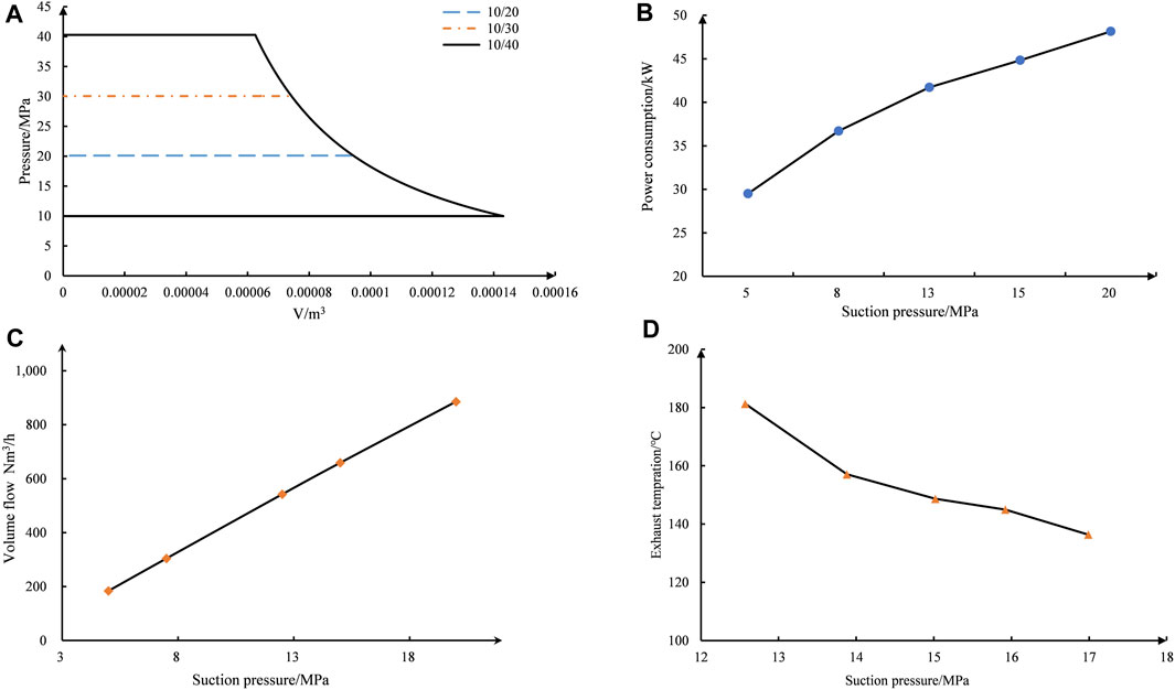
FIGURE 1. Thermal performance under Different Operating Conditions.
Figure 1D shows the trend of exhaust temperature with suction pressure when the exhaust pressure is kept constant. It can be observed that the exhaust temperature decreases with an increase in suction pressure. When the discharge pressure is kept constant, the suction pressure increases but the pressure ratio decreases. In the case where the difference in suction temperature is not significant, the gas receives more compression power and gains more heat at a larger pressure ratio, resulting in a higher exhaust temperature.
As can be seen from Figure 2A, with the increase in suction pressure, the stroke volume utilization rate of the diaphragm compressor improves to a certain extent. In the process of suction pressure rising from 5 MPa to 20 MPa, the stroke volume utilization rate gradually increases from 70% to 76%, with a larger increase in the low-pressure range. This is mainly due to the impact of the pressure ratio on the stroke, and the control of the clearance volume and the influence of the volumetric coefficient plays more important roles. Figure 2B shows that the single-cylinder piston force varies from 0 to 70 kN, reaching its maximum value and stabilizing at a 180° rotation angle. The piston force partially reverses during the suction moment, and significantly reduces to around 0° during the compression and suction processes. Overall, the imbalance in piston force is quite strong. It is best to have an opposed configuration to ensure the stable operation of the motor.
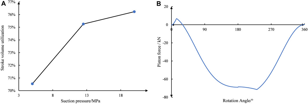
FIGURE 2. Stroke volume utilization rate and piston force under different operating conditions.
4 Conclusion
This paper analyzes the dynamics and thermodynamics of diaphragm compressors. The operating characteristics of the compressor, gas delivery capacity, power consumption, and exhaust temperature under different operating conditions are analyzed. Meanwhile, the piston force at different Angle positions is studied, and the following conclusions were drawn:
(1) The gas delivery capacity increases rapidly with the increase of suction pressure, while power consumption increases more slowly, especially in the low-pressure range, mainly due to the change of suction specific volume.
(2) The exhaust temperature varies with the suction pressure, and there is an increase of 40°C–45°C, mainly influenced by the pressure ratio.
(3) The piston force varies widely, from 0 to 70 kN, and there is a counterforce effect. It is appropriate to balance the piston forces with the opposition configuration.
As can be seen from the above research, diaphragm compressors should try to avoid low suction pressure, because the volume flow rate and stroke volume utilization rate are smaller at lower suction pressure. At the same time, in the structural design of the diaphragm compressor, it is recommended to use the cylinder head design with symmetry on both sides. This can balance the reciprocating piston force of the compressor.
Data availability statement
The original contributions presented in the study are included in the article/Supplementary material, further inquiries can be directed to the corresponding author.
Author contributions
DZ: Writing–review and editing, Methodology, Conceptualization. GW: Writing–original draft, Software, Investigation. JH: Writing–review and editing, Software, Data curation. YT: Writing–review and editing, Supervision, Investigation.
Funding
The author(s) declare that financial support was received for the research, authorship, and/or publication of this article. This work was supported and sponsored by National Natural Science Foundation of China (Grant No. 52106022), and National Natural Science Foundation of China (Grant No. 52206016).
Conflict of interest
The authors declare that the research was conducted in the absence of any commercial or financial relationships that could be construed as a potential conflict of interest.
Publisher’s note
All claims expressed in this article are solely those of the authors and do not necessarily represent those of their affiliated organizations, or those of the publisher, the editors and the reviewers. Any product that may be evaluated in this article, or claim that may be made by its manufacturer, is not guaranteed or endorsed by the publisher.
References
Chi, Y., Xu, W., Xiao, M., Wang, Z., Zhang, X., Chen, Y., et al. (2023). Fuel-cycle based environmental and economic assessment of hydrogen fuel cell vehicles in China. Energy, 282. doi:10.1016/j.energy.2023.128773
Dong, W., Shao, C., Li, X., Zhu, D., Zhou, Q., and Wang, X. (2023). Integrated planning method of green hydrogen supply chain for hydrogen fuel cell vehicles. Int. J. Hydrogen Energy 48 (48), 18385–18397. doi:10.1016/j.ijhydene.2023.01.272
Hren, R., Vujanović, A., Van Fan, Y., Klemeš, J. J., Krajnc, D., and Čuček, L. (2023). Hydrogen production, storage and transport for renewable energy and chemicals: an environmental footprint assessment. Renew. Sustain. Energy Rev., 173.
Jain, I. P. (2009). Hydrogen the fuel for 21st century. Int. J. Hydrogen Energy 34 (17), 7368–7378. doi:10.1016/j.ijhydene.2009.05.093
MegíA, P. J., VizcaíNO, A. J., Calles, J. A., and Carrero, A. (2021). Hydrogen production technologies: from fossil fuels toward renewable sources. A mini review. Energy and Fuels 35 (20), 16403–16415. doi:10.1021/acs.energyfuels.1c02501
Oliveira, A. M., Beswick, R. R., and Yan, Y. (2021). A green hydrogen economy for a renewable energy society. Curr. Opin. Chem. Eng. 33, 100701. doi:10.1016/j.coche.2021.100701
Ren, S., Jia, X., Zhang, J., Li, X., Zhang, S., and Peng, X. (2024). Diagnosis method to identify diaphragm state of diaphragm compressors for hydrogen refueling stations based on dynamic oil pressure. Int. J. Hydrogen Energy 49, 1043–1055. doi:10.1016/j.ijhydene.2023.06.214
Keywords: hydrogen refueling station, diaphragm compressors, pressure ratio, thermodynamic performance, dynamics analysis
Citation: Zhao Z, Wang G, He J and Tian Y (2024) Thermodynamics and dynamic investigation of ultra-high-pressure diaphragm compressor. Front. Energy Res. 12:1365558. doi: 10.3389/fenrg.2024.1365558
Received: 04 January 2024; Accepted: 29 February 2024;
Published: 14 March 2024.
Edited by:
Ran Tu, Huaqiao University, ChinaReviewed by:
Xuejin Zhou, Huaqiao University, ChinaJiubing Shen, Jiangsu University of Science and Technology, China
Chengzhang Wan, University of California, Los Angeles, United States
Copyright © 2024 Zhao, Wang, He and Tian. This is an open-access article distributed under the terms of the Creative Commons Attribution License (CC BY). The use, distribution or reproduction in other forums is permitted, provided the original author(s) and the copyright owner(s) are credited and that the original publication in this journal is cited, in accordance with accepted academic practice. No use, distribution or reproduction is permitted which does not comply with these terms.
*Correspondence: Zhaorui Zhao, zrzhao@usst.edu.cn