Scale-sensitivity analysis for floating energy production system with anti-motion structure under high sea conditions
 Hongtao Yuan1,2
  Yi Chen
 Mingxin Li
 Xu Bai
- 1College of Naval Engineering, Harbin Engineering University, Harbin, China
- 2Shanghai Waigaoqiao Shipbuilding and Ocean Engineering Co., LTD., Shanghai, China
- 3School of Naval Architecture and Ocean Engineering, Jiangsu University of Science and Technology, Zhenjiang, China
The heave motion of a new cylindrical floating drilling production storage and offloading system (FDPSO) with extended cylinder, anti-motion structure and a gap between the extended cylinder and anti-motion structure under high sea conditions was investigated by implementing numerical simulations for its reduced-scale laminar flow model (1:77.8) using the CFD software STAR-CCM+. The effect of changing the width (10
1 Introduction
“Floating Drilling Production Storage and Offloading System (FDPSO)” refers to adding drilling functions to an FPSO. It is a floating container-shaped production system that integrates offshore oil and gas processing, oil storage and offloading, power generation, heating, control, and living functions. FDPSO has many advantages, including low initial investment, short construction period, strong oil storage capacity, adaptable to a wide range of water depths, easy to relocate, and reusable. It is widely used in deep-sea, shallow-sea, and marginal oil fields. Most of the offshore oil and gas fields being developed or about to be developed in China belong to the category of marginal oil fields (Wang and Feng, 2011). The constant wear and corrosion of infrastructure in harsh underwater environments drives up maintenance costs, and these tasks are currently carried out primarily with remotely operated vehicles (ROVs), which often require tethered and human operators, or with autonomous underwater vehicles (AUVs), which are limited in their accessibility and maneuverability. In order to reduce the risk and cost of manual maintenance, underwater bionic robots can be used to check and measure underwater cables, offshore wind farms, electric fields and other underwater infrastructure (Gorma et al., 2021). Therefore, FDPSO is quite suitable for the development of China’s offshore oil and gas fields. After long-term development, a variety of new forms of FDPSO have emerged, including deepwater octagonal FDPSO, hourglass-shaped FDPSO, multicylinder FDPSO, and cylindrical FDPSO. Through motion response analysis of cylindrical FDPSO, it is found that cylindrical FDPSO has advantages such as low investment, low cost, and short construction period, but also has some drawbacks, such as large sway motion amplitude.
A motion response analysis of the cylindrical FDPSO reveals both strengths and weaknesses, with significant heave motion amplitudes as a drawback. To develop an internationally advanced FDPSO, Wang Shisheng (Wang and Zhao, 2014) and others conducted a conceptual design study on the deepwater octagonal FDPSO. They analyzed the impact of different oscillation plate sizes on the inherent characteristics of the octagonal FDPSO and the influence of different floating body diameters on the motion performance. Results indicate that increasing the oscillation plate size significantly alters the inherent period of the floating body. Addressing the poor wave resistance of ship-shaped FPSO, Zhao Zhijuan (Zhao, 2012) innovatively designed a new multi-cylinder FDPSO suitable for operations in the South China Sea. Computational analysis demonstrates that the inherent period of the multi-cylinder FDPSO can stay away from its wave period. Yao Yuxin (Yao and Wang, 2015) proposed a novel hourglass-shaped floating production storage and offloading system, analyzing the effects of oscillatory motion response, viscous damping, and nonlinear stiffness on the heave motion performance of the hourglass-shaped floater. This provides guidelines for the outer shape design of new floating production units. Liu Liqin (Liu and Zhang, 2019), following the SEVEN-type FPSO’s outer shape, modified the oscillation plate structure by removing the slope foot connecting the cylinder and oscillation plate, adding inclined oscillation plates. The study investigates the impact of different sea conditions on the inclination angle of the oscillation plate on its damping characteristics and anti-rolling effects. Research findings indicate that smaller cone angles provide better suppression of structural heave motion, with a 10° cone angle performing well in inhibiting longitudinal sway under various sea conditions. Ji et al., 2022 found a new drive line immersion boundary mixing method for predicting the wake characteristics of horizontal axis wind turbines. Zeng et al., 2024 summarized the research progress of nonlinear fluid dynamics of floating offshore wind turbines. Zeng et al., 2023 studied the high order harmonic load and low frequency resonance response of offshore floating wind turbine under extreme wave group. Zeng et al., 2021 conducted numerical and experimental studies on the wave breaking power of a single pile offshore wind turbine. Li et al., 2023a conducted a numerical simulation of scour waves generated by ship movement over an uneven seafloor. Li et al., 2023b studied the waves produced when a ship passes through a change in depth. Li et al., 2023c studied the interference effect of upstream waves generated by depth changes in catamarans. Li et al., 2023d conducted a time domain numerical simulation of positive speed motion of multiple ships in waves. Li et al., 2019 studied stable hydrodynamic interactions between human swimmers.
This paper conducts CFD (Computational Fluid Dynamics) numerical simulation analysis on the heave motion of a cylindrical FDPSO equipped with extended cylindrical bodies and a box-type motion reduction structure. Various height and width conditions of the motion reduction structure are considered to investigate their impact on the heave motion of the cylindrical FDPSO. The numerical simulation provides heave motion and vertical force time history curves, enabling an analysis of the influence of the motion reduction structure’s width and height. Additionally, the study elucidates the physical mechanisms behind how the dimensions of the motion reduction structure affect the heave motion of the FDPSO, based on the flow field information obtained from numerical simulations.
2 Mathematical models and numerical methods
2.1 Governing equations for incompressible viscous fluids
In the numerical simulation of this paper, the hydrodynamic load of the floating drilling production storage and unloading device is obtained by solving the incompressible viscous fluid outside the device. In three dimensions, for a homogeneous incompressible fluid, the density of the fluid remains constant during the motion, then the N−S equations for the three-dimensional incompressible viscous fluid can be expressed as:
where:
2.2 Free surface capture method
In this paper, the numerical simulation involves the study of water and air two-phase flow. Euler-Euler model is used to describe the two-phase fluid in the calculation domain, and the VOF (Hirt and Nichols, 1981) (Volume of Fluid) method and the variable of phase volume fraction is introduced to track the phase interface in the calculation domain (Guo, 2017).
The fractional function of the VOF model is:
The transport equation of the VOF model function follows the convection equation as follows:
where U is the fluid velocity and Ur is the velocity field used to compress the interface.
The density and viscosity in the continuity equation and momentum equation above are obtained by weighted average of the proportion of the two-phase fluid, and the function is as follows:
where subscript w represents water and subscript
2.3 Wave generation and wave parameter setting
JONSWAP was measured and analyzed by the North Sea Wave Joint Project. The spectrum describes irregular waves (Du, 2021). The setting of wave parameters is shown in Table 1.
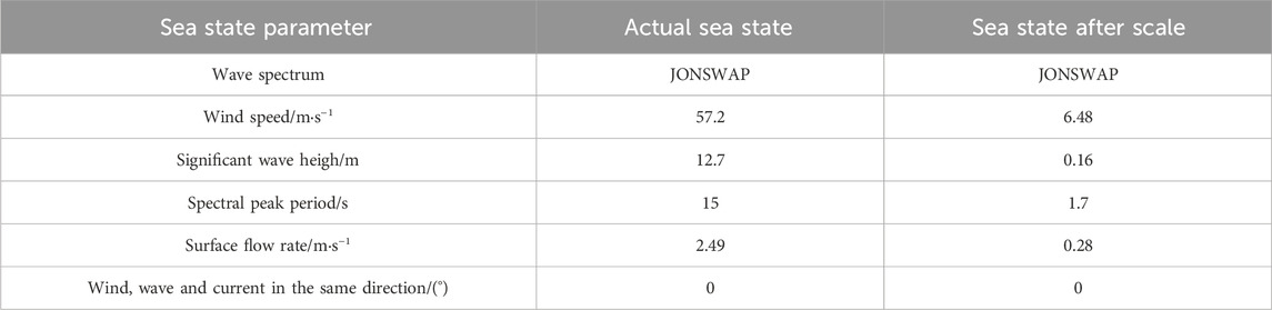
TABLE 1. Wave parameters.
2.4 FDPSO motion theory
In the study of CFD numerical simulation, it is very important to solve the motion of floating body in fluid. In the case that only the single freedom motion of the floating body is considered, the motion equation of FDPSO can be established based on the direct equilibrium method of D ‘Alembert’s principle:
Where: m is the mass of the floating body; y is the displacement of the floating body in the direction of motion; c is the viscous damping coefficient; k is the stiffness coefficient; F is the exciting force on the floating body in the direction of motion.
When FDPSO does heave motion, the force F consists of the hydrodynamic force Fv and the additional mass inertial force Fa caused by the heave additional mass, i. e:
By substituting equations (8) and (9) into Equation 7, the equation of FDPSO heave motion can be obtained:
The inherent period of FDPSO is:
In order to reduce the heave performance of FDPSO, the natural period of the platform heave motion can be increased by increasing the additional mass of the structure, so that the natural period of the platform heave motion can be further away from its wave period.
3 Physical model
Based on the actual size of the platform in Table 2, the model was established according to the scale ratio of 1:77.8. The 3D geometric model profile of the platform established based on SolidWorks is shown in Figure 1.
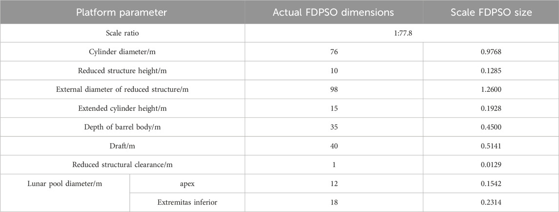
TABLE 2. Physical parameters.
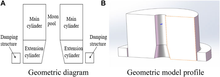
FIGURE 1. Schematic diagram of the geometric model. (A) Geometric diagram. (B) Geometric model profile.
4 Numerical simulation and results discussion
4.1 Computational domain settings and meshing
The model used in this paper is an axisymmetric structure, so half of the model is used for calculation domain setting and grid division. The dimensions of the computational domain are 8
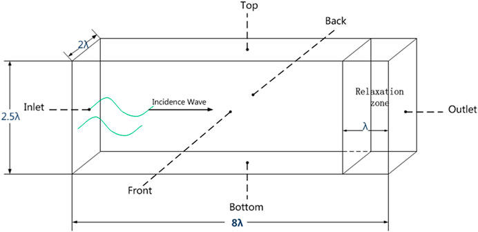
FIGURE 2. Computational domain sketch.
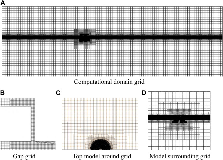
FIGURE 3. Fluid mesh. (A) Computational domaingrid. (B) Gap grid. (C) Top model around grid. (D) Model surrounding grid.
4.2 Grid convergence verification
In order to conduct convergence analysis on the number of grids, this paper considers the heave attenuation in still water (Bai and Li, 2020), and generates three different numbers of grids when the width and height of the structure with a gap are both 10 m. According to the different number of grids, grid 1, grid 2 and grid 3 are divided, as shown in Table 3.
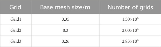
TABLE 3. Mesh convergence verification numerical value of cylindrical FDPSO example.
Three different mesh density models of 1.5 million, 2 million and 2.83 million were used to calculate the heave free attenuation curve, as shown in Figure 4.
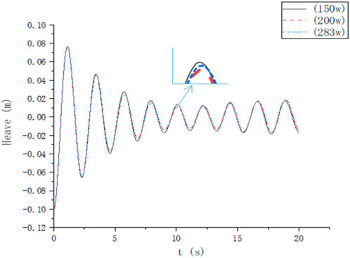
FIGURE 4. Heave free attenuation motion curve of models with different mesh densities.
Using three different grid density models (1.5 million, 2 million, and 2.83 million cells), the study calculates heave free decay curves for the cylindrical FDPSO with a gap motion reduction structure having widths and heights of 10 m, as depicted in Figure 4. The results obtained using 2 million grid cells closely match those obtained using 2.83 million grid cells, while the results from 1.5 million grid cells show slight discrepancies. Considering computational efficiency, subsequent calculations will use the 2 million grid cells.
4.3 Result analysis
The cylindrical FDPSO used in this study has extended cylindrical bodies and a motion reduction structure. Analyzing the sensitivity of heave motion suppression in the cylindrical FDPSO with varying dimensions of the motion reduction structure, the study investigates different scenarios for the width (10–15 m) and height (10–15 m) of the motion reduction structure, while keeping the other dimension fixed at 10 m. Simulation results for heave motion under different scenarios are presented, and the effect of the motion reduction structure dimensions on the FDPSO’s heave motion is analyzed. The study explores multiple numerical cases considering various widths and heights of the motion reduction structure, presenting the displacement values for different scenarios in Table 4.

TABLE 4. Drainage weight of each size model of anti-motion structure.
4.3.1 Effect of reduced structure width on model heave motion
The heave time history curves for models with widths of 10, 12, and 15 m are simulated and presented in Figure 5. Performing a fast Fourier transform on selected data points, the amplitude-frequency curves shown in Figure 5 demonstrate that increasing the width of the motion reduction structure leads to a gradual reduction in the floater’s amplitude.

FIGURE 5. Motion amplitudes of different widths of heave plate.
Statistical analysis of the heave time history curves for different widths yields the inherent periods of heave motion for models with varying motion reduction structure widths, as shown in Table 5. The data indicates that increasing the width of the motion reduction structure results in a larger inherent period of heave motion for the cylindrical FDPSO. Compared to the model with a motion reduction structure width of 10 m, models with wider structures exhibit increased inherent periods of 4.93%, 12.32%, and 19.21% for widths of 11, 12, and 13 m, respectively.
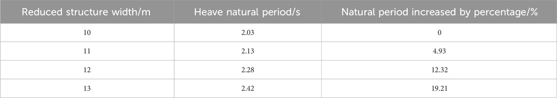
TABLE 5. Heave natural period of different anti-motion structure width.
Table 6 compares the maximum and minimum values of heave motion for motion reduction structure widths of 10 m and 15 m. The results show that, when considering only floater heave motion, increasing the motion reduction structure width from 10 m to 15 m leads to a decrease in the amplitude of vertical forces, reducing the heave motion of the platform. The heave motion for the platform with a motion reduction structure width of 15 m is reduced by 47.7% compared to the structure with a width of 10 m.
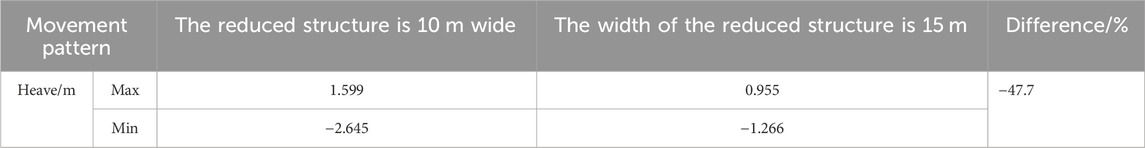
TABLE 6. Comparison of heave motion between 10 m and 15 m width.
The floating body heave motion is numerically simulated by CFD method. The vorticity of the model with the same height (10 m) and width of 11 m and 14 m in the fifth motion cycle is shown in Figure 6. As can be seen from Figure 6, during the floating body’s movement, vortices are generated at the sharp edges and gaps of the reducing structure and the extended cylinder. When FDPSO moves downward from the equilibrium position to the lowest position (5–5.25T), vortices in an upward direction are generated at the top sharp corner of the reducing structure, vortices generated at the bottom sharp corner of the reducing structure form accumulation at the bottom of the floating body, and vortices at the gap move upward. When FDPSO moves upward from the lowest position to the equilibrium position (5.25–5.5T), during the upward movement, the vortices gradually start to fall off, and the vortices falling off at the sharp corners above the reducing structure gradually pile up above the reducing structure, and the vortices falling off at the sharp corners below the reducing structure move backward, and new vortices will be generated at the sharp corners and gaps of the reducing structure. When FDPSO moves upward from the equilibrium position to a higher position (5.5–5.75T), a downward vortex is generated at the outer sharp corner of the reduced structure. When FDPSO moves downward from the highest position to the equilibrium position (5.75–6.0T), an upward vortex is generated at the sharp corner of the reducing structure, and the vortex gradually falls off with the increase of time. The vortex shed in the early stage continues to move away from the cylindrical FDPSO and gradually dissipates in the surrounding flow field. On the whole, the vortex structure generated by sharp edges and gaps in the process of motion presents a tendency of dissipation and propagation to the surrounding flow field (Bai and Li, 2020). The vorticity generation and dissipation of models with large widths are increased compared with those with small widths.
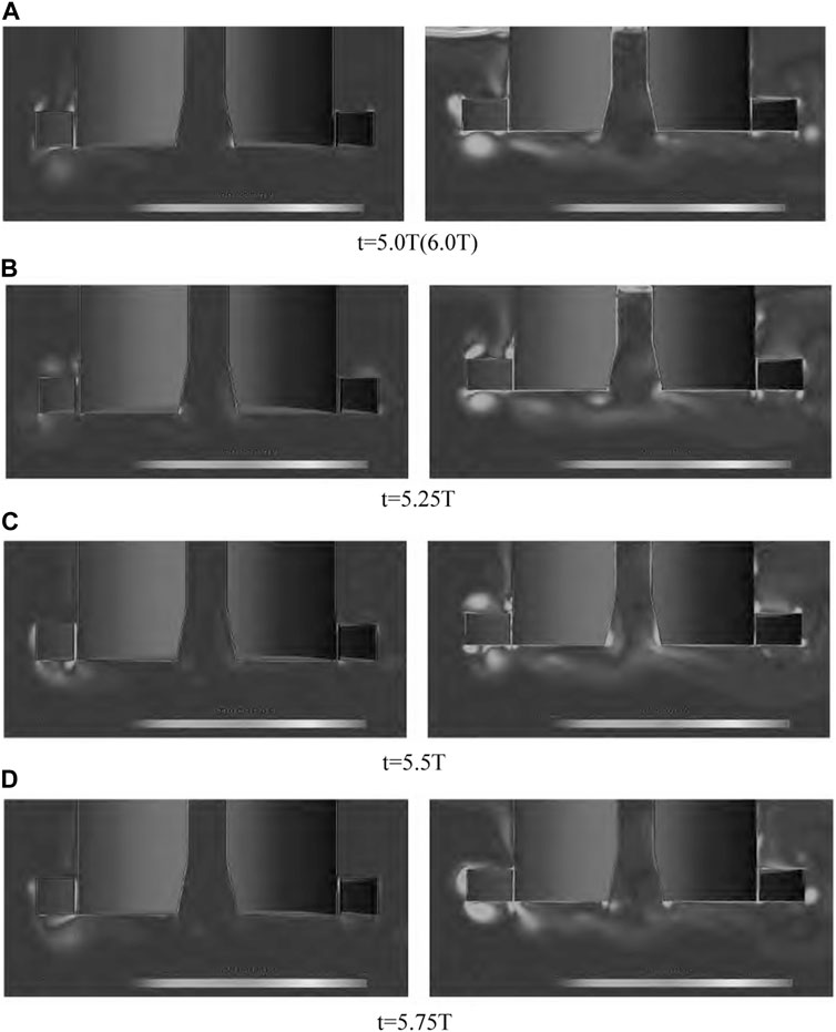
FIGURE 6. The vortex field distribution of different anti-motion structure width. (A) t=5.0T (6.0T). (B) t = 5.25T. (C) t = 5.5T. (D) t = 5.75T.
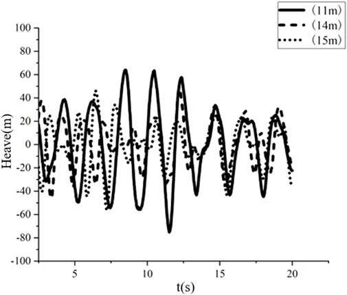
FIGURE 7. Vertical stress time curve of different decreasing structure widths.
In summary, the increase of the width of the cylindrical FDPSO damping structure increases the natural period of the heave motion of the structure, making it far away from the range of the main energy period of the wave, and can effectively slow down the heave motion of the platform.
4.3.2 Effect of reduced structure height on model heave motion
Through numerical simulation of the heave motion of the model with a height of 10, 11, 12, 13, 14 and 15 m of the reduced structure, the heave time curve is obtained. Figure 8 shows the heave time curve of the model with a height of 13 and 15 m. Take some data for fast Fourier transform and draw the amplitude-frequency curve as shown in Figure 8. As can be seen from Figure 8, the height of the subtractive structure increases, while the floating body amplitude gradually decreases.

FIGURE 8. Motion amplitudes of different widths of heave plate.
According to the statistics of the heave time curve of the different height of the subtraction structure, the natural heave period of the model with different height of the subtraction structure can be obtained, as shown in Table 7. The natural period of the real scale platform movement is obtained by scaling ratio conversion. When the height of the subtraction structure is 10 m, its heave natural period is 17.91 s. When the height is 13 m, the natural period is 18.52 s. When the height is 15 m, the natural period is 19.23 s. The data in Table 7 show that the natural period of heave motion of cylindrical FDPSO increases with the increase of the height of the subtraction structure. Compared with the model with a height of 10 m, the natural period of other height models increases by 3.45% and 7.93%, respectively.
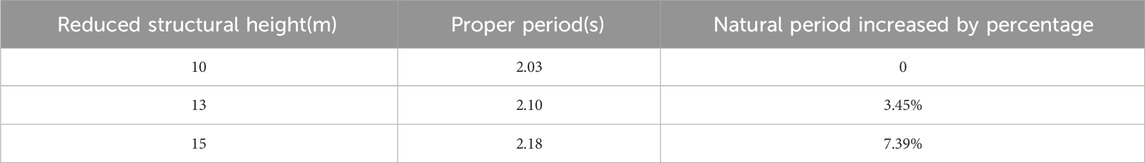
TABLE 7. Sag natural period of different height of subtraction structure.
Table 8 compares the maximum and minimum values of heave motion of a subtractive structure with a height of 13 m and a height of 15 m. It can be seen that when only the heave motion of the floating body is considered, when the height of the decreasing structure increases from 13 m to 15 m, the amplitude of the vertical force of the floating body decreases, which reduces the heave motion of the platform. The heave motion of the platform with the height of the decreasing structure is 43.1% lower than that of the platform with the height of the decreasing structure is 13 m.
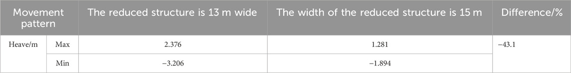
TABLE 8. Comparison of heave motion between 13 m and 15 m heights.
The vorticity diagram of the model with constant width (10 m) and height of 12 m and 15 m in the sixth motion cycle is shown in Figure 9. It can be seen that vortices are generated in the sharp edges and gaps of the reducing structure and the extended cylinder during the floating body’s movement. When FDPSO moves downward from the equilibrium position to the lowest position (6–6.25T), vortices in the upward direction are generated at the top sharp corner of the reducing structure, vortices generated at the bottom sharp corner of the reducing structure form accumulation at the bottom of the floating body, and vortices at the gap move upward. When FDPSO moves upward from the lowest position to the equilibrium position (6.25–6.5T), the vortices gradually start to fall off during the upward movement, and the vortices falling off at the sharp corners above the reducing structure gradually pile up above the reducing structure, and the vortices falling off at the sharp corners below the reducing structure move backward, and new vortices will be generated at the sharp corners and gaps of the reducing structure. When FDPSO moves upward from the equilibrium position to a higher position (6.5–6.75T), a downward vortex is generated at the outer sharp corner of the structure. When the FDPSO moves downward from the highest position to the equilibrium position (6.75–7.0T), an upward vortex is generated at the sharp corner of the reducing structure, and the vortex gradually falls off with the increase of time. The vortex shed in the early stage continues to move away from the cylindrical FDPSO and gradually dissipates in the surrounding flow field. On the whole, the vortex structure generated by edge sharp corners and gaps in the process of motion shows a tendency to dissipate and propagate to the surrounding flow field. The vorticity generation and dissipation increase with the increase of height, but the vorticity change is not obvious compared with that with the increase of width.
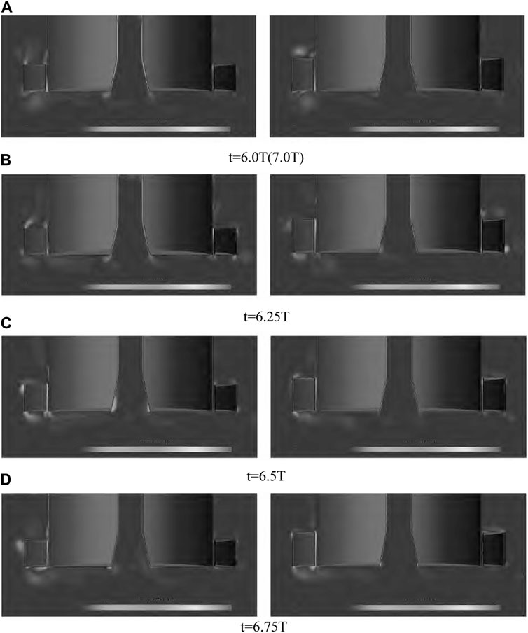
FIGURE 9. The vortex field distribution of different anti-motion structure height. (A) t=6.0T (7.0T). (B) t = 6.25T. (C) t = 6.5T. (D) t = 6.75T.
Figure 10 shows the time history curve of the vertical force of the model with different height of the subtraction structure. In this paper, the effect of fluid viscosity is considered in the research process. The viscosity of liquid will produce resistance to objects in motion, that is, the viscous pressure resistance. Relative movement will cause the pressure difference between the front and back of the reduced structure. The vertical stress amplitude of the floating production unit is reduced, but the change of the height of the damping structure has little effect on the viscous pressure difference.

FIGURE 10. Time-history curves of vertical force with different height of anti-motion structure.
In summary, the natural period of heave motion can be increased with the increase of height of cylindrical FDPSO, but the increase of natural period caused by the increase of height is smaller than that caused by the increase of width.
5 Conclusion
In this paper, STAR-CCM+, a computational fluid dynamics software, is used to numerically simulate the heave motion of a new cylindrical FDPSO with different widths and heights under the action of irregular waves. According to the calculation results, the following conclusions are drawn:
(1) under the condition of fixed height of the subtraction structure, increasing the width of the subtraction structure can effectively increase the natural period of the heave motion of the new cylindrical FDPSO, making it far away from the cycle range of the main energy of the wave, that is, increasing the width can inhibit the heave motion of the floating production unit.
(2) Under the condition that the width of the reduced structure is fixed, the increase of the height of the reduced structure also increases the natural period of the heave motion of the new cylinder type FDPSO to a certain extent, which has an inhibiting effect on its heave motion.
(3) During the movement of the new cylinder type FDPSO, vortices are generated at the sharp edges of the extended cylinder and the reducing structure, especially at the gap between the reducing structure and the extended cylinder.
(4) The generation and shedding of vortices around the high-width subtraction structure model is significantly increased compared with that of the low-width subtraction structure model, resulting in an increase in the friction resistance of the subtraction structure; Compared with the width change, the generation and shedding of the vortex caused by the change of height is relatively weak, and the increase of height leads to the increase of friction resistance of the structure.
(5) The increase of the size of the subtraction structure can inhibit its sag motion. And compared to the height increasing the suppression effect on floating platform, increasing the width of the platform more obvious suppression effect.
Data availability statement
The original contributions presented in the study are included in the article/Supplementary material, further inquiries can be directed to the corresponding author.
Author contributions
HY: Conceptualization, Data curation, Formal Analysis, Methodology, Validation, Visualization, Writing–original draft. YC: Formal Analysis, Investigation, Software, Validation, Visualization, Writing–original draft. ML: Investigation, Methodology, Project administration, Resources, Writing–review and editing. LC: Formal Analysis, Validation, Visualization, Writing–review and editing. XB: Investigation, Project administration, Writing–review and editing. YL: Investigation, Project administration, Writing–review and editing.
Funding
The author(s) declare that financial support was received for the research, authorship, and/or publication of this article. National Natural Science Foundation of China, Surface Project, 42276225, Research on magnetic-electric-fluid-Solid multi-field and multiphase Coupling Characteristics and Power generation Efficiency of improved magnetic levitation VIVACE Tidal current power generation Device, 2023-01-01 to 2026-12-31, 540,000 yuan, in research, participate Science and Technology Department of Jiangsu Province, Natural Science Foundation of Jiangsu Province (Surface Research Project), BK20211342, Study on fluid-induced vibration Mechanism and Energy capture Characteristics of multi-cylindrical oscillators supported by magnetic levitation, 2021-07 to 2024-07, 100,000 yuan, participated.
Conflict of interest
Author HY was employed by Shanghai Waigaoqiao Shipbuilding and Ocean Engineering Co., LTD.
The remaining authors declare that the research was conducted in the absence of any commercial or financial relationships that could be construed as a potential conflict of interest.
Publisher’s note
All claims expressed in this article are solely those of the authors and do not necessarily represent those of their affiliated organizations, or those of the publisher, the editors and the reviewers. Any product that may be evaluated in this article, or claim that may be made by its manufacturer, is not guaranteed or endorsed by the publisher.
References
Bai, J., and Li, Y. (2020). Optimization design of heave suppression structure for new cylindrical FPSO. J. OCEAN Eng. 38 (1), 20–29.
Du, Y. H. (2021). Numerical analysis of ship motion response characteristics in irregular waves. J.THE Ocean. Eng. 39 (3), 31–41.
Gorma, W., Post, M. A., White, J., Gardner, J., Luo, Y., Kim, J., et al. (2021). Development of modular bio-inspired autono-mous underwater vehicle for close subsea asset inspection. Appl. Sci. 11 (12), 5401. doi:10.3390/app11125401
Guo, L. (2017). Numerical simulation of tank sloshing based on VOF method. Harbin, China: D.Harbin Engineering University.
Hirt, C. W., and Nichols, B. D. (1981). Volume of fluid (VOF) method for the dynamics of free boundaries. J. Comput. Phys. 39 (1), 201–225. doi:10.1016/0021-9991(81)90145-5
Ji, R., Sun, K., Zhang, J., Zhu, R., and Wang, S. (2022). A novel actuator line-immersed boundary (AL-IB) hybrid approach for wake characteristics prediction of a horizontal-axis wind turbine[J]. Energy Conversion and Management 253, 115193.
Li, M., Yuan, Z.-M., Bai, X., Li, Y. Z., Cheng, Y., and Tao, L. (2023a). Numerical modelling of wash waves generated by ships moving over an uneven bottom. China Ocean Engineering 37 (1), 145–153.
Li, M., Yuan, Z.-M., and Tao, L. (2023b). Wash waves generated by ship moving across a depth change. Ocean Engineering 275, 114073.
Li, M., Chen, Y., Yuan, Z.-M., Cheng, Y., and Tao, L. (2023c). Interference effects on the upstream wave generated by the catamaran moving across a depth change. Ocean Engineering 287, 115939.
Li, M., Pan, S., Cheng, Y., Yuan, Z.-M., and Tao, L. (2023d). Time-domain numerical simulation for multi-ships moving in waves with forward speed. Ocean Engineering 290, 116325.
Li, M., Yuan, Z.-M., Ji, C., Li, L., Jia, L., and Atilla, I. (2019). Steady hydrodynamic interaction between human swimmers. Journal of Royal Society:Interface 16, 1–12.
Liu, L. Q., and Zhang, X. R. (2019). Damping characteristics of cone damping structure on FDPSO based on CFD. J.CHINA OFFSHORE Platf. 34 (3), 25–31.
Wang, S. S., and Zhao, J. R. (2014). Global performance analysis for deep water octagon FDPSO. J.S HI P OCE Eng. 43 (3), 183–186+189.
Wang, T. Y., and Feng, Y. X. (2011). Advanced development of research on new concept FPSOs. J.S HI P OCE Eng. 40 (5), 184–188+192.
Yao, Y. X., and Wang, W. H. (2015). Analysis on heave motion performance of new sandglass-type floating body. J.Huazhong Univ. Sci.&Tech.Natural Sci. Ed. 43 (7), 129–132.
Zeng, X., Shao, Y., Feng, X., Xu, K., Jin, R., and Li, H. (2024). Nonlinear hydrodynamics of floating offshore wind turbines: A review[J]. Renewable and Sustainable Energy Reviews 191, 114092.
Zeng, X., Shi, W., Feng, X., Shao, Y., and Li, X. (2023). Investigation of higher-harmonic wave loads and low-frequency resonance response of floating offshore wind turbine under extreme wave groups[J]. Marine Structures 89, 103401.
Zeng, X., Shi, W., Michailides, C., Zhang, S., and Li, X. (2021). Numerical and experimental investigation of breaking wave forces on a monopile-type offshore wind turbine[J]. Renewable Energy 175, 501–519.
Keywords: cylindrical FDPSO, anti-motion structure, heave motion, CFD, scale sensitivity
Citation: Yuan H, Chen Y, Li M, Chen L, Bai X and Li Y (2024) Scale-sensitivity analysis for floating energy production system with anti-motion structure under high sea conditions. Front. Energy Res. 12:1368327. doi: 10.3389/fenrg.2024.1368327
Received: 10 January 2024; Accepted: 04 March 2024;
Published: 13 March 2024.
Edited by:
Fengmei Jing, Beijing Institute of Technology, ChinaReviewed by:
Yang Luo, Northwestern Polytechnical University, ChinaYang Zhou, University of Strathclyde, United Kingdom
Copyright © 2024 Yuan, Chen, Li, Chen, Bai and Li. This is an open-access article distributed under the terms of the Creative Commons Attribution License (CC BY). The use, distribution or reproduction in other forums is permitted, provided the original author(s) and the copyright owner(s) are credited and that the original publication in this journal is cited, in accordance with accepted academic practice. No use, distribution or reproduction is permitted which does not comply with these terms.
*Correspondence: Mingxin Li, mingxin.li@just.edu.cn