Multi-time-scale voltage control of the distribution network with energy storage equipped soft open points
 Xiaohua Ding
  Xingying Chen
- College of Electrical and Power Engineering, Hohai University, Nanjing, China
The integration of distributed generation (DG) units into distribution networks (DNs) has brought about several operational challenges, including voltage issues and increased power loss. Energy storage equipped soft open points (E-SOPs) can accurately and flexibly control active and reactive power flows to address these problems. Additionally, the photovoltaic (PV) inverter and the network reconfiguration (NR) play a significant role in voltage control by adjusting the reactive power and the topology of the DN, respectively. However, due to differences in response times, there is a lack of systematic coordination between NR and the inverters of the E-SOP and PV. This paper proposes a multi-time-scale voltage control model that includes day-ahead NR scheduling, inter-day droop control optimization of the PV and E-SOP, and real-time local droop control. Considering the uncertainties of renewable DG outputs and loads, a robust optimization method is used in the day-ahead stage to obtain a reliable network structure. Then, with more accurate intra-day predictions, a stochastic optimization method is used to obtain the optimal state-of-charge interval, aiming to provide a flexible regulation range for battery energy storage to cope with the power fluctuations during the real-time stage. In addition, to address the intra-day voltage control model with bilinear constraints of the droop control function, a particle swarm optimization method is used. The results are verified on a 33-bus DN system through comparative analyses, showing effective performance.
1 Introduction
The proliferation of renewable distributed generation (DG) within distribution networks (DNs) is rapidly expanding. Due to the stochastic property and uncertainty of renewable DG output, the extensive collaboration of renewable DG may cause problems such as increased line overload and voltage fluctuations, which present significant operational challenges for the DN (Hua et al., 2019). Moreover, implementing infrastructure upgrades and curtailing renewable DG power are also not economically efficient.
To address this challenge, network reconfiguration (NR) is a common and effective measure. It can change the DN topology by operating the switches. Based on this, the power flow in lines and substations can be reallocated according to the reconfiguration results. Currently, extensive studies have been conducted on NR, and their objectives mainly focus on power loss deduction, voltage deviation reduction, and load balance function in the DN (Li et al., 2023). Azizi et al. (2023) proposed a DN reconfiguration approach that considers renewable DG, soft open points (SOPs), and protection devices, aiming to minimize the power loss while ensuring the correct operation of protection devices under normal and fault conditions. Meanwhile, the loop-closing situation during the NR process was considered by Jun et al. (2016) to obtain the optimum NR scheme without power interruption. Moreover, in order to obtain the optimal NR strategy, various modeling and optimization methods have been applied. A mixed-integer quadratic programming (MIQP) problem was constructed by Yang et al. (2021) with the consideration of NR and modified DistFlow, which can be efficiently solved using commercial solvers. Quang et al. (2023) applied a genetic algorithm to obtain the NR strategy and enhance the operational efficiency of the DN, aiming to address the impact on the solving time caused by a large number of binary variables. Additionally, in order to minimize the risk of falling into local optima, artificial intelligence algorithms such as reinforcement learning and Q-learning have been widely used (Dong et al., 2023; Gholizadeh et al., 2023). The literature above has considered comprehensive research on the involvement of NR in the DN and demonstrated favorable operational performance. However, due to the physical limitations of line switches, the NR method needs to be determined in advance and cannot effectively adapt to the frequent fluctuations in renewable DG output (Zhang et al., 2019).
To achieve fast tracking of power fluctuations in the DN, the installation of SOPs, which can achieve the precise control of power flow between feeders and achieve dynamic reactive power compensation (Wang et al., 2016), has drawn significant attention. In general, the existing literature on DN operation optimization based on SOPs mainly focuses on the economic or power quality aspects of the DN (Cao et al., 2021). Li et al. (2023) investigated the output characteristics of SOPs and developed a reactive power optimization model. Li et al. (2022) proposed an adaptive voltage control strategy for SOPs based on a deep deterministic policy gradient network and showed the high efficiency of the SOPs in maintaining the safe and stable operation of the DN. However, due to the high cost of SOPs, the number of SOPs installed in the DN may fall short of fulfilling the requirements for DN operation (Hu et al., 2022). Thus, it is important to investigate a collaborative optimization approach of SOPs and NR to enhance the regulatory capability of the DN (Dai, 2022).
Considering the difference in the responding time between SOPs and NR, the existing literature on DN operation optimization based on SOPs and NR mainly obtains optimal solutions through constructing multi-layer optimization models (Hu et al., 2023). Pamshetti and Singh (2022) and Wang X. et al. (2022) both constructed a two-stage collaborative optimization model integrating SOPs and a battery energy storage system (BESS), but they all ignore the collaboration of traditional voltage control methods such as NR. Furthermore, Nazir et al. (2019) presented a two-stage chance-constrained voltage control model to minimize the expected power loss, which involves determining the operational strategy for OLTC, CB, and voltage regulators in the first stage and optimizing the reactive power output of inverters in the second stage. A multi-time-scale model was constructed by Li et al. (2017) and Shi and Zheng (2018) based on the coordination of NR and SOPs to achieve the time-series voltage optimization of the DN. However, these articles primarily focus on optimizing the power set point of power electronic devices such as SOPs at different time intervals, without taking into account their real-time droop regulation performance. Given the inevitability of forecast errors in renewable DG prediction and the shorter time duration of voltage fluctuation caused by stochastic renewable DG output than the prediction duration (Sun et al., 2023), there is a need to construct a multi-time-scale optimization model considering real-time local voltage control.
Recently, the collaboration of real-time local voltage control and day-ahead intra-day control has drawn significant attention and mainly focused on optimizing the droop control function of a photovoltaic (PV) inverter and SOPs (Chu et al., 2021). Regarding PV droop control optimization, a real-time voltage/var droop control function was optimized by Wang B. et al. (2020). It segments the droop control function into multiple sections, and a maximum value comparison function is used. These will result in increased nonlinearity and complexity in solving the model. Zhang and Xu (2020) proposed a central and local voltage/var control strategy to reduce real-time voltage deviation by using a linear droop controller for PV inverters and showed its high efficiency in regulating the voltage quality of the DN. Considering the high performance of PV droop control function, it can be used in this paper. Regarding SOP droop control optimization, Li et al. (2019) and Hu et al. (2020) optimized the V-Q droop control function of SOPs based on the pre-determined reference set point; they divided the droop function into several pieces and optimized them separately. However, the nonlinear model and the large newly introduced binary variables increase the computation burdens. Moreover, considering that due to the large R/X value of the DN, the active power also significantly influences the voltage profiles during operation. It is necessary to consider the optimization of the V-P droop function of SOPs (Sun et al., 2021a). Based on this, Sun et al. (2021a) proposed a multi-time-scale energy management robust optimization model with multiple-terminal SOPs. In this model, the droop control function is formulated through V2-P and V2-Q models. However, given that the master port of SOPs needs to monitor the power fluctuations of other ports to ensure its steady operation, the implementation of V2-P droop control may limit the adjustability of its master port. The utilization of energy storage equipped soft open points (E-SOPs) may offer an effective solution to this issue. By integrating the BESS into the SOP DC line, internal power equilibrium can be achieved without the need to adjust the master port. Consequently, each port of the E-SOP can independently adjust the V-P droop control based on its port voltage level. Recently, existing literature considering E-SOP regulation is mainly based on prediction data to obtain an operating set point during the day (Chen et al., 2022; Sarantakos et al., 2022), and its local droop regulation characteristics of active and reactive power are often ignored. In addition, the limited capacity of the BESS and inadequate planning of its charging and discharging strategy may lead to insufficient operation range during real-time operation. Wang Y. et al. (2020) and Wang Y. et al. (2022) introduced an interval optimization model to allocate the optimal SOC interval for the BESS. This approach aims to ensure that the BESS can have sufficient adjustment capacity to cope with the uncertainty of renewable DG outputs and loads throughout the day. This can serve as a reference in the management of the BESS in E-SOPs.
The above literature review showed that existing works do not comprehensively consider the coordination of NR and the droop control model of E-SOPs and PV inverters in the multi-time-scale, including the real-time local voltage control. Moreover, the SOC interval optimization of the BESS in E-SOPs has also not been integrated. In addition, a multi-stage hierarchical framework is required to systematically coordinate the NR with the E-SOPs and PV inverter. Thus, this paper introduces a multi-time-scale voltage control model considering the factors mentioned above. The main contributions of this paper are summarized as follows:
(1) A multi-time-scale voltage control method is proposed to efficiently coordinate the NR and inverter control of the BESS and E-SOP, aiming to minimize the voltage fluctuation and power loss of the DN. In the day-ahead stage, the robust optimization (RO) method is applied to obtain the reliable NR strategy of the DN. Then, in the intra-day stage, operation set points and droop control functions of the PV inverter and E-SOP, as well as the SOC interval of the BESS, are obtained. Lastly, in the real-time stage, the automatic control of the E-SOP and PVs is carried out based on the local voltage measurements.
(2) In the intra-day stage, a droop control optimization model of the PV inverter is constructed. Moreover, the V-P and V-Q droop control function of the E-SOP is obtained with the coordination of SOC interval optimization in multiple scenarios to enhance the regulation ability of the DN in the real-time stage. The SOC interval will be used to restrict the charging and discharging power of the BESS to ensure the sufficient regulation range of the BESS for E-SOP V-P control in the real-time stage.
(3) To tackle the intra-day optimization problem with the bilinear constraints of the droop control function, a particle swarm optimization (PSO) method is introduced to promote the solving efficiency.
2 Coordination framework of multi-time-scale DN voltage optimization
This paper introduces a multi-time-scale voltage control method to minimize the power loss and voltage fluctuation of the DN. The proposed method consists of three parts, namely, day-ahead optimization, intra-day optimization, and real-time adjustment, whose framework is shown in Figure 1.

Figure 1. Proposed multi-time-scale voltage optimization method framework.
In the day-ahead stage, with the day-ahead renewable DG and load predictions, the NR strategy of the DN is determined to obtain the reliable DN topology, considering switch action limitation. Moreover, the optimal power dispatch of PV inverters and E-SOP ports is considered, but they will be re-optimized in the intra-day stage.
In the intra-day stage, based on the hour-ahead prediction, inverter operation set points and the parameters of the E-SOP V-P and V-Q droop control function and the PV V-Q droop control function are obtained. Moreover, considering the time coupling of the BESS and the uncertainties in renewable DG output and loads, the SOC interval of the BESS is optimized, and a rolling method is used to reduce prediction errors in the intra-day model (Wang B. et al., 2020). During the rolling process, only the results of the first hour are executed, and the remaining parts are discarded until the next horizon is updated.
In the real-time adjustment stage, the inverters of the PV and E-SOP regulate the active and reactive power according to their droop control function. Meanwhile, to ensure the stable operation of the E-SOP, the BESS will monitor the required change in the active power at E-SOP ports and compensate for the power imbalances that may arise between them.
3 Day-ahead coordinate voltage control model
3.1 E-SOP operating model
The E-SOP achieves the parallel connection of DC/AC inverters and BESS DC/DC inverters on a DC bus, with their AC side linked to the distribution grid feeder lines. Each inverter independently regulates the active and reactive power at its ports within its capacity, enabling flexible and interconnected operation of the distribution grid. Moreover, the collaboration of the BESS eliminates the requirement for real-time power balance between the E-SOP ports, thereby improving the adjustability of the E-SOP. The operation model of the E-SOP can be expressed as follows:
where
Eqs 1, 2 construct the time coupling relationship of the E-SOP based on the time absolute continuity of the BESS. Eq. 3 ensures the real-time balance of active power within the E-SOP, thereby forming the space coupling relationship of energy power. Eq. 4 is the expression of power loss, and constraint (5) represents the capacity constraint of the E-SOP.
3.2 Distribution network reconfiguration model
The NR model of the DN can be expressed as follows:
where
Constraints (6)–(10) set the limitations on the branch power and node voltage through the Big M method, ensuring that if
Through adjusting the value of the switch control variable
3.3 Day-ahead voltage control model
The day-ahead optimization model aims to simultaneously obtain the NR strategy of the DN and the dispatch of inverter reactive power in order to minimize the power loss and voltage fluctuation. The model can be formulated as follows:
s.t. (1)–(11),
Eqs 12, 13 represent the average bus voltage deviation and branch power loss, respectively, and the bus voltage and branch apparent power are restricted by constraints (14) and (15), respectively. Constraints (16)–(20) and constraints (1)–(2) collectively represent the operational limitations of the BESS in the E-SOP. Constraint (21) limits the reactive power output of the PV inverters. In addition, constraint (22) limits the action number of switches in the DN, where
3.4 Robust optimization for uncertainties
To address the uncertainties of renewable DG outputs and loads, a RO method (Wang et al., 2021) is introduced. This method searches for the worst scenario based on the uncertainty set. Then, the most reliable solution can be obtained under the worst scenario of uncertainty realization. In this paper, the uncertainty set can be modeled as
In this uncertainty set,
Thus, the detailed expression of the proposed RO model is as follows:
s.t. (1)–(22).
In model (24),
Moreover, it is worth noting that after solving model (24), only
4 Intra-day coordinate voltage control model
4.1 SOC interval optimization model for the BESS in the E-SOP
Based on
where
4.2 Droop control model of the E-SOP
Considering that the E-SOP inverters have a redundant capacity, adopting the traditional droop curve with deadband may waste the inverter capacity. To make full use of the inverter capacity, the no-middle-deadband droop control function is applied (Xu et al., 2022), which is shown in Figure 2. Moreover, given that the active power is also an important influencing factor in the voltage fluctuation of the DN, adopting the V-P droop control function is also a significant way to promote the real-time security of the DN (Sun et al., 2021a). Thus, the droop control function of the E-SOP can be summarized as follows:
where
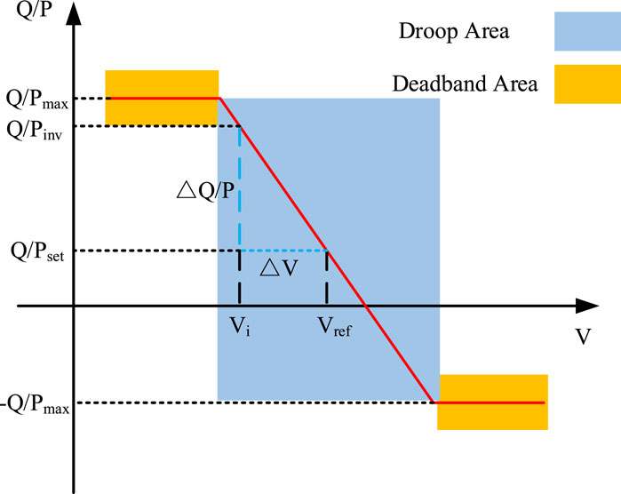
Figure 2. Droop control function of the energy storage equipped soft open point (E-SOP).
It is worth noting that, in the real-time stage, the E-SOP control system will first calculate the SOC after regulation and port-required adjustment power based on local voltage measurement and the droop control curve. If the calculated SOC exceeds the interval, the BESS will reduce the adjustment power to maintain the SOC within the interval. At this point, the maximum power that the BESS can charge/discharge will be prioritized to support the port of the E-SOP with higher voltage deviation.
4.3 Droop control model of PV inverters
Given the redundant capacity of PV inverters and their potential as a voltage var control device, in this section, a Q-V droop control function of the PV inverter is also constructed with reference to the droop control curve discussed in Section 4.2.
where
Eq. 36 denotes the actual reactive power output of the PV inverter. Eqs. (37)–(40) form the expression for the droop control function of PV inverters. Eq. 37 calculates the deviation of the node voltage, and Eq. 38 represents the reactive power adjustment considering the voltage change based on the slope of the droop function. The slope of the droop control curve is limited by constraint (39). Constraint (40) limits the range of reactive power output and set points.
4.4 Intra-day stochastic optimization model
In this research, it was considered that the NR strategy obtained from the RO method is sufficiently reliable, and the accuracy of intra-day rolling forecasts is high. Compared to obtaining an optimal droop curve that adapts to the worst-case scenario, acquiring the droop model that can achieve the expected optimal performance across multiple potential operational scenarios will be more efficient in reducing the voltage deviations caused by real-time stage power fluctuations. Thus, a stochastic optimization (SO) method is applied. In this method, the scenario sets are randomly generated based on intra-day forecast data to obtain the optimal expected control strategy. Moreover, considering that the probability distribution may not be known, a sample average approximate method is applied. Thus, the intra-day voltage optimization model can be expressed as follows:
s.t. (1)–(10) (12)–(20), (25)–(40),
where
5 PSO-based intra-day solution method
The PSO algorithm is an evolutionary algorithm based on the observation and research of bird predatory behavior. It was proposed by Dr Eberhart and Kennedy in 1995. This algorithm was initially inspired by the regularity of bird clustering activities, and then, a simplified model was established by using swarm intelligence. In the PSO method, each bird is a particle, and the process of foraging based on the instinct of birds is the process of finding the optimal solution in the solution space (Swari et al., 2022). Compared with other modern stochastic intelligent optimization algorithms, PSO has been widely used due to its advantages of simple implementation and no need for gradient information (Liu et al., 2019), and it can also effectively solve nonlinear optimization problems.
The PSO method first initializes a group of random particles, and then, the optimal solution is found through iteration. In each iteration, the particles update the iteration by tracking the local optimal extremum
where
It is worth noting that the parameter
where
The steps to use the PSO algorithm to solve the proposed intra-day coordinated voltage optimization model can be seen in Figure 3 and can be summarized as follows (Feng et al., 2023):
(1) The particles to be solved are chosen:
(2) PSO parameters and initial particle position and velocity are initialized.
(3) Model (41) is optimized based on Gurobi, and the speed and position of particles are updated according to Eqs 42, 43. Then, the fitness values of each particle are calculated.
(4) The local and global optimal solutions of the algorithm are updated based on the fitness values in each particle.
(5) Whether
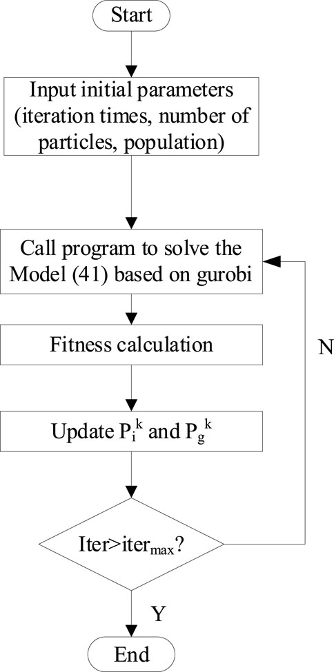
Figure 3. Flowchart of the proposed particle swarm optimization (PSO) algorithm.
6 Case study
6.1 System setting
A 33-bus distribution network is applied to test the proposed method, and the topology is shown in Figure 4. This system has 33 nodes with 37 branches, and each branch is equipped with a switch to respond to the scheduling demands of NR (Li et al., 2023). The rated power of renewable DG, BESS, and E-SOP inverters is given in Table 1. In addition, the prediction profiles of renewable DG output and load are shown in Figure 5, regarded as the expected prediction. The prediction intervals are set as ±10% of the renewable DG output and ±10% of the load output. Then, 100 scenarios are generated to participate in the intra-day optimization. In addition, the rated maximum output power of the BESS is 400 kW, and the capacity of the BESS in the E-SOP is 600 kWh (Huang et al., 2022). Meanwhile, the allowed voltage range of the DN is set as 0.95 p.u–1.05 p.u., and the maximum action number of switches is 6. Additionally, in the PSO method, the maximum iteration number is 15, and the population size is set as 20.
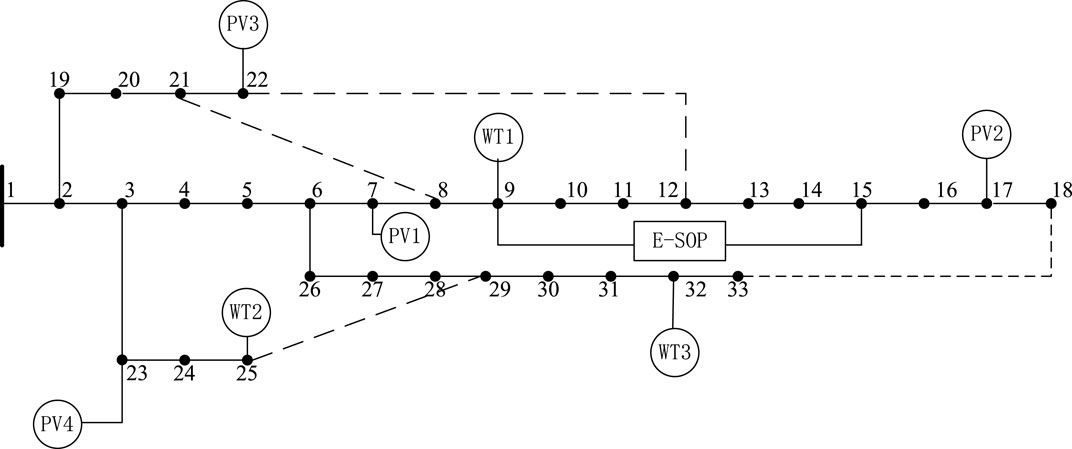
Figure 4. Topology of the 33-bus distribution network (DN) system.
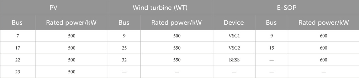
Table 1. Rated power of photovoltaic (PV), battery energy storage system (BESS), and energy equipped soft open point (E-SOP) inverters.
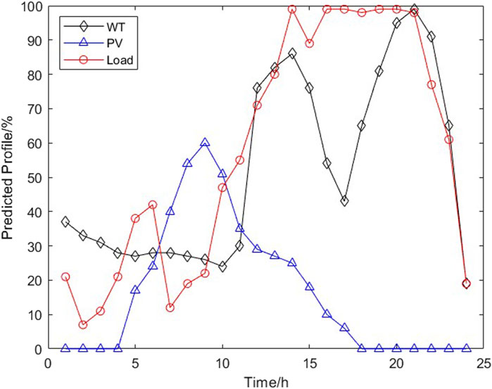
Figure 5. Prediction profile of renewable distributed generation (DG) and load.
The proposed optimization model is programmed on the MATLAB 2022b platform with the YALMIP toolbox and solved using Gurobi 10.0.
6.2 Day-ahead operating results
By solving the day-ahead voltage operating model considering NR, the optimal NR strategy is obtained, as shown in Figure 6. By controlling switches between nodes 7 and 8 and nodes 12 and 13 into a disconnected state and switches between nodes 21 and 8 and nodes 18 and 33 into a connected state, NR can adjust the distribution of renewable DG and load by altering the DN topology to promote the balanced distribution of the system source and loads, thereby promoting the safe operation of the DN. The calculated average power loss cost and voltage range throughout the entire day were determined to be 2.448 MW and 0.192 p.u., respectively.

Figure 6. Network reconfiguration (NR) operating result in the day-ahead stage.
In addition, without the NR and the inverter reactive power regulation, the voltage range under the expected condition is [0.948, 1.0017], which is out of the allowed voltage range. On the other hand, with the coordination of inverter voltage control and NR, the voltage range can be [0.965, 1.0011], indicating that the change in the voltage can be maintained in the acceptable range.
6.3 Intra-day operating results
In the intra-day stage, the N in the rolling procedure is set as four; based on this, the SOC interval of the BESS can be obtained by solving the proposed model (41), and the result is shown in Figure 7. The BESS will start discharging power before 4:00 because of the low renewable DG prediction power output. Then, with the increase in the PV output, the BESS will continue to charge from 4:00 to 11:00. Moreover, the operating range of the BESS is relatively flat due to the high WT output power between 12:00 and 19:00. Furthermore, with the increase in load demand and the decrease in renewable DG output, the BESS will be forced to discharge power to fulfill the peak loads.
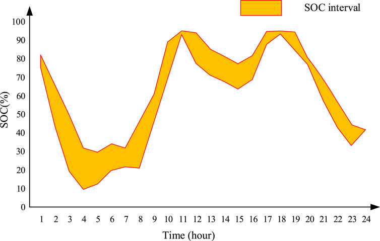
Figure 7. Battery energy storage system (BESS) state-of-charge (SOC) interval.
Then, taking the load peak period of 21:00 to 22:00 as an example, the total expected renewable DG generation and loads are 1.31 MW and 3.678 MW, respectively. Figure 8 shows the solving process of the proposed intra-day optimizing problem; it can be found that in the
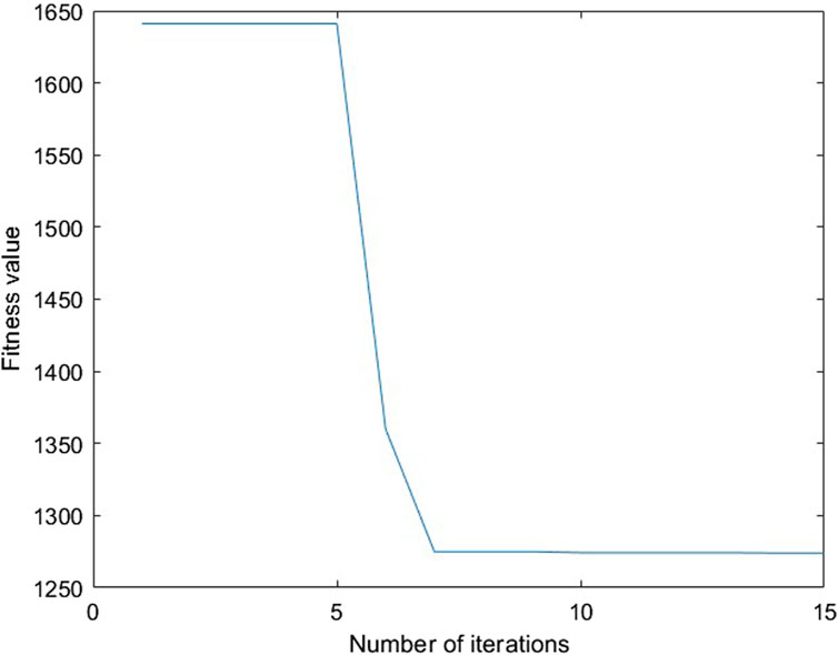
Figure 8. Convergence process of the proposed PSO method.
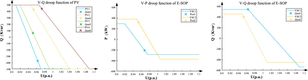
Figure 9. Droop function for the period 21:00–22:00.
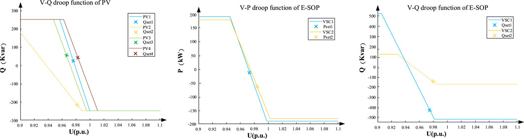
Figure 10. Droop function for the period 9:00–10:00.
6.4 Operating performance in the real-time stage and comparison with other methods
In the real-time stage, the inverters of PVs and E-SOP that operate under the droop control function can change the active and reactive output power in response to the measurement of local bus voltage based on the optimized droop control curve. Figure 11 shows the real-time stage BESS operating states in terms of SOC under some of the scenarios. It can be found that during the real-time stage, the BESS can achieve a flexible transfer of power on the time scale by adjusting its charging/discharging power, thereby enhancing the temporal flexibility of power distribution network operation. Moreover, during the periods of 6:00–8:00 and 17:00–19:00, the BESS exhibits minimal fluctuations due to the reduced load and increased renewable DG outputs. This indicates a relatively balanced active power within the DN, and the demand for active power adjustment of E-SOP ports during these times is low. Furthermore, in the tested scenarios, the BESS can maintain SOC within its intervals while addressing real-time fluctuations in the DN.

Figure 11. Real-time stage BESS operating states.
In addition, to analyze the real-time system operating security performance, the peak load period of 21:00–22:00 is taken as an example; another two voltage control methods are applied for comparison, given as follows:
Method A: A two-stage central voltage control method that optimizes the NR and inverter output power of the PV inverter and E-SOP without considering the droop control function. The inverter output power dispatch is re-optimized per hour and fixed.
Method B: A multi-time scale voltage control model considering PV and E-SOP Q-V control function. The active power output set points of the E-SOP are determined based on hourly forecast data and rolling optimization during the intra-day stage.
For each forecast error, 1,000 test scenarios are randomly generated in the uncertainty set to test the operating security of the two methods. The results are shown in Table 2. In this test, a reliable probability index (RPI) is defined to reflect the system security performance:
where
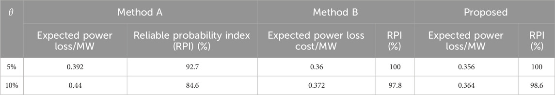
Table 2. Comparison of the three methods in the real-time stage.
The RPI and the expected power loss cost are shown in Table 2, and
Moreover, the probability distribution of voltage at bus 18 under the ±5% interval testing set is shown in Figure 12. In this figure, method A has the widest voltage range and largest voltage violation rate. The voltage profile in method B and the proposed method has significantly improved compared with method A. Meanwhile, compared with method B, the proposed method demonstrates a smaller voltage deviation and better voltage waveform during the real-time stage, attributed to the incorporation of the V-P droop control function.

Figure 12. Probability distribution of voltage at bus 18 for the period 21:00–22:00.
7 Conclusion
This paper proposes a multi-time-scale voltage control method, aiming to minimize the power loss and voltage fluctuation of the DN. In this method, the reliable NR strategy is obtained via the RO method. Meanwhile, to tap the optimized potentials of the PV inverter and E-SOP, the SOC interval of the BESS and the droop control function of the PV inverter and E-SOP are fully modeled. In addition, to solve the bilinear constraints, a PSO method is applied to reduce the computing burden. The results indicate that the proposed method can minimize power loss and voltage fluctuation and improve the reliability of the DN under uncertainties.
This study mainly focuses on the coordination between the BESS and linear droop control function without deadband. Future work will focus on constructing a more universally applicable droop control function to facilitate the coordinated optimization of multiple regulating devices such as the E-SOP, BESS, PV inverters, and capacitors.
Data availability statement
The original contributions presented in the study are included in the article/Supplementary Material; further inquiries can be directed to the corresponding author.
Author contributions
XD: data curation, methodology, software, supervision, and writing–original draft. XC: funding acquisition, investigation, resources, writing–review and editing, and validation. KY: data curation, funding acquisition, investigation, validation, and writing–review and editing. FC: data curation, formal analysis, methodology, and writing–original draft. BW: investigation, supervision, validation, and writing–review and editing.
Funding
The author(s) declare that financial support was received for the research, authorship, and/or publication of this article. This research was supported by the National Natural Science Foundation of China (52277089 and 52307091).
Conflict of interest
The authors declare that the research was conducted in the absence of any commercial or financial relationships that could be construed as a potential conflict of interest.
Publisher’s note
All claims expressed in this article are solely those of the authors and do not necessarily represent those of their affiliated organizations, or those of the publisher, the editors, and the reviewers. Any product that may be evaluated in this article, or claim that may be made by its manufacturer, is not guaranteed or endorsed by the publisher.
References
Azizi, A., Vahidi, B., and Nematollahi, A. F. (2023). Reconfiguration of active distribution networks equipped with soft open points considering protection constraints. J. Mod. Power Syst. Clean Energy 11 (1), 212–222. doi:10.35833/mpce.2022.000425
Cao, W., He, J., and Zhou, Y. (2021). “Voltage control in distribution networks with soft open point and on-load tap changer,” in 2021 IEEE 4th International Conference on Electronics Technology, Chengdu, China (ICET), 446–451.
Chen, Y., Yang, G., Song, Z., Sun, M., and Zhou, S. (2022). “Optimal configuration method of soft open point considering flexibility of distribution system,” in 2022 IEEE 5th International Conference on Automation, Electronics and Electrical Engineering, Shenyang, China (AUTEEE), 524–529.
Chu, G., Zhang, Y., Ge, L., and Wan, L. (2021). Multi-time-scale voltage optimization of flexible interconnected distribution network with self-energy storage. Automation Electr. Power Syst. 45 (9), 71–79. doi:10.7500/AEPS20200223007
Dai, B. (2022). “Multi-objective optimization model of distribution network reconfiguration considering soft open point,” in 2022 China International Conference on Electricity Distribution, Changsha, China (CICED), 468–472.
Dong, L., Wu, Y., Zhang, T., Wang, X., Hao, Y., and Guo, L. (2023). Reinforcement learning based double-layer optimization method for active distribution network with soft open point. Automation Electr. Power Syst. 47 (6), 59–68. doi:10.7500/AEPS20220327004
Fang, S., Huang, X., Kong, L., Niu, T., Chen, G., and Liao, R. (2023). Distribution network reconfiguration method with health operating area of energy storage life and voltage security constraints. Proc. CSEE, 1–11. https://kns.cnki.net/kcms/detail/11.2107.tm.20230919.1453.015.html
Feng, W., Zhang, W., and Huang, S. (2023). A novel parameter estimation method for PMSM by using chaotic particle swarm optimization with dynamic self-optimization. IEEE Trans. Veh. Technol. 72 (7), 8424–8432. doi:10.1109/tvt.2023.3247729
Gholizadeh, N., Kazemi, N., and Musilek, P. (2023). A comparative study of reinforcement learning algorithms for distribution network reconfiguration with deep Q-learning-based action sampling. IEEE Access 11, 13714–13723. doi:10.1109/access.2023.3243549
Hu, R., Wang, W., Chen, Z., Wu, X., Jing, L., Ma, W., et al. (2020). Coordinated voltage regulation methods in active distribution networks with soft open points. Sustainability 12 (22), 9453. doi:10.3390/su12229453
Hu, R., Wei, W., Wu, X., Chen, Z., and Ma, W. (2022). Interval optimization based coordinated control for distribution networks with energy storage integrated soft open points. Int. J. Electr. Power and Energy Syst. 136, 107725. doi:10.1016/j.ijepes.2021.107725
Hu, R., Zhao, C., Ma, W., and Shao, B. (2023). “An interval optimization based two-stage voltage control method for distribution networks,” in 2023 IEEE 6th International Electrical and Energy Conference, Hefei, China (CIEEC), 4456–4461.
Hua, H., Qin, Y., Hao, C., and Cao, J. (2019). Optimal energy management strategies for energy Internet via deep reinforcement learning approach. Appl. Energy 239, 598–609. doi:10.1016/j.apenergy.2019.01.145
Huang, Y., Zhang, Q., Zhang, A., Yan, Z., and Gao, B. L. X. (2022). Distribution network reconfiguration considering demand-side response with high penetration of clean energy. Power Syst. Prot. Control 50 (1). doi:10.19783/j.cnki.pspc.210284
Jun, L., Fan, Y., and Peng, W. (2016). “Distribution network reconfiguration method considering loop closing constraints,” in 2016 IEEE PES Asia-Pacific Power and Energy Engineering Conference (Xi'an: APPEEC), 1419–1423.
Li, C., Dai, Y., Wang, P., and Xia, S. (2023). Active and reactive power coordinated optimization of active distribution networks considering dynamic reconfiguration and SOP. IET Renew. Power Gener. doi:10.1049/rpg2.12814
Li, P., Ji, H., Yu, H., Zhao, J., Wang, C., Song, G., et al. (2019). Combined decentralized and local voltage control strategy of soft open points in active distribution networks. Appl. Energy 241, 613–624. doi:10.1016/j.apenergy.2019.03.031
Li, P., Ji, H., Zhao, J., Song, G., Ding, F., Wu, J., et al. (2017). Coordinated control method of voltage and reactive power for active distribution networks based on soft open point. IEEE Trans. Sustain. Energy 8 (4), 1430–1442. doi:10.1109/tste.2017.2686009
Li, P., Wei, M., Ji, H., Xi, W., Yu, H., Wu, J., et al. (2022). Deep reinforcement learning-based adaptive voltage control of active distribution networks with multi-terminal soft open point. Int. J. Electr. Power and Energy Syst. 141, 108138. doi:10.1016/j.ijepes.2022.108138
Liu, H., Huang, G., Wang, C., Liu, H., Wang, Z., Xu, Z., et al. (2019). “Reactive power optimization of power grid with photovoltaic generation based on improved particle swarm optimization,” in 2019 IEEE Innovative Smart Grid Technologies - Asia, Chengdu, China (ISGT Asia), 1536–1540.
Liu, Z., and Wang, L. (2022). A robust strategy for leveraging soft open points to mitigate load altering attacks. IEEE Trans. Smart Grid 13 (2), 1555–1569. doi:10.1109/tsg.2021.3134176
Nazir, F. U., B, C. P., and Rabih, A. J. (2019). A two-stage chance constrained volt/var control scheme for active distribution networks with nodal power uncertainties. IEEE Trans. Power Syst. 34 (1), 314–325. doi:10.1109/tpwrs.2018.2859759
Pamshetti, V. B., and Singh, S. P. (2022). Coordinated allocation of BESS and SOP in high PV penetrated distribution network incorporating DR and CVR schemes. IEEE Syst. J. 16 (1), 420–430. doi:10.1109/jsyst.2020.3041013
Quang, P. P., Anh Quoc, H. C., and Minh, Q. T. (2023). “Distribution network reconfiguration using genetic algorithm considering load profile and the penetration of distributed generation. 2023,” in Asia Meeting on Environment and Electrical Engineering (EEE-AM), Hanoi, Vietnam. 01-06.
Sarantakos, I., Peker, M., Zografou-Barredo, N., Deakin, M., Patsios, C., Sayfutdinov, T., et al. (2022). A robust mixed-integer convex model for optimal scheduling of integrated energy storage—soft open point devices. IEEE Trans. Smart Grid 13 (5), 4072–4087. doi:10.1109/tsg.2022.3145709
Shi, T., and Zheng, H. (2018). “Multi-time scale control strategy of distribution network based on SOP and energy storage,” in 2018 International Conference on Smart Energy Systems and Technologies, Seville, Spain (SEST), 1–6.
Sun, D., Sun, Y., Sun, Y., Liu, R., Wang, X., and Wang, Y. (2023). Switching control strategy for an energy storage system based on multi-level logic judgment. Front. Energy Res. 11. doi:10.3389/fenrg.2023.1199574
Sun, F., Ma, J., Yu, M., and Wei, W. (2021b). Optimized two-time scale robust dispatching method for the multi-terminal soft open point in unbalanced active distribution networks. IEEE Trans. Sustain. Energy 12 (1), 587–598. doi:10.1109/tste.2020.3013386
Sun, F., Yu, M., Wu, Q., and Wei, W. (2021a). A multi-time scale energy management method for active distribution networks with multiple terminal soft open point. Int. J. Electr. Power and Energy Syst. 128, 106767. doi:10.1016/j.ijepes.2021.106767
Sun, T., Zou, P., Yang, Z., Zhong, H., Dai, G., and Xia, Q. (2016). A multi-stage solution approach for dynamic reactive power optimization. Power Syst. Technol. 40 (06), 1804–1810. doi:10.13335/j.1000-3673.pst.2016.06.029
Swari, M. H. P., Handika, I. P. S., Satwika, I. K. S., and Wahani, H. E. (2022). “Optimization of single exponential smoothing using particle swarm optimization and modified particle swarm optimization in sales forecast,” in 2022 IEEE 8th Information Technology International Seminar, Surabaya, Indonesia (ITIS), 292–296. doi:10.1109/itis57155.2022.10010034
Wang, B., Zhang, C., and Dong, Z. (2020). Interval optimization based coordination of demand response and battery energy storage system considering SOC management in a microgrid. IEEE Trans. Sustain. Energy 11 (4), 2922–2931. doi:10.1109/tste.2020.2982205
Wang, B., Zhang, C., Dong, Z., and Li, X. (2021). Improving hosting capacity of unbalanced distribution networks via robust allocation of battery energy storage systems. IEEE Trans. Power Syst. 36 (3), 2174–2185. doi:10.1109/tpwrs.2020.3029532
Wang, B., Zhang, C., Li, C., Li, P., Dong, Z., and Lu, J. (2022). Hybrid interval-robust adaptive battery energy storage system dispatch with SoC interval management for unbalanced microgrids. IEEE Trans. Sustain. Energy 13 (1), 44–55. doi:10.1109/tste.2021.3103444
Wang, C., Song, G., Li, P., Yu, H., Zhao, J., and Wu, J. (2016). Research and prospect for soft open point based flexible interconnection technology for Smart distribution network. Automation Electr. Power Syst. 40 (22), 168–175. doi:10.7500/AEPS20160620009
Wang, X., Guo, Q., Tu, C., Che, L., Yang, W., Xiao, F., et al. (2022). A two-layer control strategy for soft open points considering the economical operation area of transformers in active distribution networks. IEEE Trans. Sustain. Energy 13 (4), 2184–2195. doi:10.1109/tste.2022.3189089
Wang, Y., Zhao, T., Ju, C., Xu, Y., and Wang, P. (2020). Two-level distributed volt/var control using aggregated PV inverters in distribution networks. IEEE Trans. Power Deliv. 35 (4), 1844–1855. doi:10.1109/tpwrd.2019.2955506
Xu, R., Zhang, C., Xu, Y., Dong, Z., and Zhang, R. (2022). Multi-objective hierarchically-coordinated volt/var control for active distribution networks with droop-controlled PV inverters. IEEE Trans. Smart Grid 13 (2), 998–1011. doi:10.1109/tsg.2021.3126761
Yang, T., Guo, Y., Deng, L., Sun, H., and Wu, W. (2021). A linear branch flow model for radial distribution networks and its application to reactive power optimization and network reconfiguration. IEEE Trans. Smart Grid 12 (3), 2027–2036. doi:10.1109/tsg.2020.3039984
Zeng, B., and Zhao, L. (2013). Solving two-stage robust optimization problems using a column-and-constraint generation method. Operations Res. Lett. 41 (5), 457–461. doi:10.1016/j.orl.2013.05.003
Zhang, C., and Xu, Y. (2020). Hierarchically-coordinated voltage/VAR control of distribution networks using PV inverters. IEEE Trans. Smart Grid. 11 (4), 2942–2953. doi:10.1109/tsg.2020.2968394
Zhang, C., Xu, Y., and Dong, Z. (2020). Robustly coordinated operation of a multi-energy micro-grid in grid-connected and islanded modes under uncertainties. IEEE Trans. Sustain. Energy 11 (2), 640–651. doi:10.1109/tste.2019.2900082
Zhang, C., Yan, X., Zhaoyang, D., and Jayashri, R. (2019). Three-stage robust inverter-based voltage/var control for distribution networks with high-level PV. IEEE Trans. Smart Grid 10 (1), 782–793. doi:10.1109/tsg.2017.2752234
Keywords: battery energy storage systems, droop control, distribution network, state-of-charge interval, particle swarm optimization, multi-time scale
Citation: Ding X, Chen X, Yu K, Cao F and Wang B (2024) Multi-time-scale voltage control of the distribution network with energy storage equipped soft open points. Front. Energy Res. 12:1374704. doi: 10.3389/fenrg.2024.1374704
Received: 22 January 2024; Accepted: 08 April 2024;
Published: 07 May 2024.
Edited by:
Cheng Wang, North China Electric Power University, ChinaReviewed by:
Zhaoyuan Wu, North China Electric Power University, ChinaDi Liu, Tsinghua University, China
Liang Yuan, Central South University, China
Copyright © 2024 Ding, Chen, Yu, Cao and Wang. This is an open-access article distributed under the terms of the Creative Commons Attribution License (CC BY). The use, distribution or reproduction in other forums is permitted, provided the original author(s) and the copyright owner(s) are credited and that the original publication in this journal is cited, in accordance with accepted academic practice. No use, distribution or reproduction is permitted which does not comply with these terms.
*Correspondence: Feifan Cao, caoff154@163.com