An analytical method for free vibrations of the fuel rod with non-uniform mass of small modular reactor
 Guowei Yang
 Yong Zhang3,4*
 - 1Hefei Institutes of Physical Science, Chinese Academy of Sciences, Hefei, China
- 2University of Science and Technology of China, Hefei, China
- 3International Academy of Neutron Science, Qingdao, China
- 4National Institute of Neutronic Energy Co., Ltd., Qingdao, China
- 5Shandong Key Laboratory of Neutron Science and Technology, Qingdao, China
- 6Institute of Nuclear Science and Technology, Shandong University, Jinan, China
The intricate internal structure of fuel rods results in a non-uniform mass distribution, making it imperative to employ analytical methods for accurate assessment. The study utilizes Euler beam theory to derive the transverse vibration equation for beams with varying mass distribution. The approach involves transforming the non-uniform mass beam into a multi-segment beam with concentrated mass points. Modal function relationships between adjacent uniform segments are established based on continuous conditions at connection points. This transformation leads to the conversion of the variable coefficient differential equation into a nonlinear matrix equation. The Newton-Raphson method is then applied to calculate the characteristic equation and mode shapes, essential for determining natural frequencies. To validate precision, the results obtained are compared with those derived from the finite element method. Furthermore, the developed method is employed to assess the impact of gas plenum location and length on the natural frequency of fuel rods. The proposed methodology serves as a rapid design tool, particularly beneficial during the design phase of fuel rods with non-uniform mass distribution, aiding in configuring structural aspects effectively.
1 Introduction
Small modular reactor (SMR) has aroused extensive attention because of the low-cost and high fitness (Hussein, 2020). Among various Gen IV reactors, the Lead-based Fast Reactor (LFR) is known for its favorable neutron properties, superior heat transfer capability (Bandini et al., 2011), excellent fuel breeding performance, and inherent safety. These characteristics make LFR particularly promising for miniaturized applications (Takahashi and Sekimoto, 2007; OECD Nuclear Energy Agency, 2014). Recent years have seen the proposal of various Lead-based Fast Reactor (LFR) concepts worldwide. These include the SVBR-100 (Grape et al., 2014) and BREST-OD-300 projects (Zrodnikov et al., 2011) in Russia, the MYRRHA project (Orlov et al., 2005) in Belgium, the ELFR and ALFRED projects (Hamid et al., 2001) in the European Union, and the CLEAR-I project in China (Roberto et al., 2014; Wang et al., 2015; Wu, 2016a; Wu, 2016b; Wu et al., 2016).
The fuel rod is a crucial component in a nuclear reactor, primarily serving to contain nuclear fuel, regulate neutron flux, induce nuclear fission reactions, and generate heat energy. Within fuel rods, Fission Gases (FG) are continuously generated during burn-up, escaping to the fuel-to-cladding gap and eventually reaching the gas plenum. The release of FG increases the internal pressure, potentially accelerating the degradation of the mechanical properties of the cladding that surrounds the fuel. The gas plenum serves as a crucial component in the fuel rod design, intended to mitigate pressure changes and minimize their impact. The mass of the gas plenum section is significantly lighter than the other parts of the fuel rod, resulting in an uneven axial distribution of mass in the fuel rod. The fuel rod is a typical beam model with variable cross-sectional parameters.
Numerous scholars have extensively delved into theoretical and numerical investigations concerning beams with arbitrary variable cross-sectional parameters. Early researchers predominantly explored diverse methodologies to address the natural frequencies of specific configurations of such beams. Heidebrecht (Ramesh and Rao, 2013), for instance, extended the vibration equation of variable cross-sectional parameters beams into a Fourier series, thereby deriving approximate natural frequencies and modes for simply supported instances. Bailey (Bailey, 1978), by integrating the Hamiltonian principle with numerical methods, resolved the frequency equation and determined the natural frequencies of cantilevered variable cross-sectional parameters beams. Gupta (Gupta, 1985) employed the finite element method to obtain numerical solutions for the natural frequencies and modes of circular beams with linearly varying diameters. Olver (Olver, 1974), utilizing the WKB (Wentzel, Kramers, Brillouin (Avdoshka and Mikhasev, 2001)) method, addressed the natural frequencies and modes of free vibrations in variable cross-sectional parameters Euler beams. Given that the WKB method fundamentally relies on a small parameter, introducing a parameter representing the reciprocal of the natural frequency, its limitations become apparent when dealing with beams of low natural frequencies, leading to inaccuracies in frequency solutions. Consequently, the WKB method is best suited for variable cross-sectional parameters Euler beams characterized by substantial stiffness; however, for beams with low stiffness, significant errors arise in the computations. Moreover, numerous studies have scrutinized circular cone beams with linearly varying cross-sectional radii, employing methodologies such as orthogonal analysis (Spigler and Vianello, 2007), Bessel equations (Caruntu, 1996; Auciello and Nolè, 1998), infinite series (Rosa and Auciello, 1996), Frobenius power exponent method (Ö and Kaya, 2006), and Differential Transform Method (DTM) (BanerjeeSuJackson, 2006).
Upon analyzing the current research landscape regarding the calculation of vibration characteristics in beams with variable cross-sectional parameters, it becomes evident that diverse methods are employed. The utilization of these mathematical approaches for calculating the vibration characteristics of such beams entails a cumbersome and intricate solving process, making it less conducive to engineering applications. Additionally, the establishment and computation process of finite element models require a considerable amount of time.
This paper investigates the calculation method for the transverse vibration characteristics of Euler beams with non-uniform mass. Based on Euler beam theory, non-uniform mass is equivalently represented as a uniform mass beam with multiple concentrated mass points. The transverse vibration equations for beams with concentrated masses are derived, and the resulting equations are validated through comparisons with results obtained using the finite element software ANSYS in various instances. The accuracy of the method is confirmed through these comparisons. Additionally, the study explores the impact of mass distribution on the natural frequencies of fuel rods.
2 General theoretical formulations for non-uniform beam
Assuming the length of the beam is L, the mass per unit length is ρ, and the bending stiffness is a constant EI. Consider the beam as a Bernoulli-Euler beam. The Euler-Bernoulli beam theory satisfies some fundamental assumptions, including a length-to-thickness ratio greater than 10, neglecting shear deformation of the beam, as well as ignoring the influence of the rotational inertia of the cross-section about the neutral axis.
The bending equation of the beam can be used to describe the behavior of lateral bending. For free vibration, neglecting external loads, the bending equation is given by Eq. 1.
Where y(x, t) represents the lateral displacement at point x of the beam at time t.
The free vibration of the curved beam is a fourth-order partial differential equation. To solve the differential equation, the separation variable method can be employed resulting in Eq. 2:
In Eq. 2,
In Eq. 3, ω represents the natural frequency of the system. ω signifies the natural circular frequency of lateral vibrations, and φ represents the phase angle determined by the initial conditions of the vibration.
Y(x) is the mode function of the transverse vibration of the beam, which can be expressed in Eq. 4.
In Eq. 5, λ is the eigenvalue, typically represented as a solution to the modal equation and can be obtained through Eq. 5.
The fuel rod contains internal fillers with non-uniform mass distribution, making it impractical to calculate using the above-mentioned methods. By simplifying the internal fillers into concentrated mass points, the fuel rod is then modeled as a beam with concentrated mass points.
2.1 Theory formula for beam with single concentrated mass point
The beam is divided into two parts at a concentrated mass point, as shown in Figure 1. The lengths of the two beam segments are denoted as a and b. Both beams have consistent density ρ, bending stiffness EI, and a concentrated mass M.
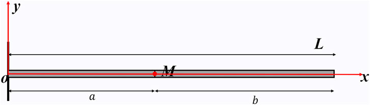
FIGURE 1. Single concentrated mass point model.
Assume that the two beams have different vibration mode functions, denoted as Y1x) and Y2x), as shown in Eq. 6 and Eq. 7).
Each mode function involves four parameters to be determined. The presence of concentrated mass points influences the boundary conditions of the two equations. Taking a cantilever beam as an example (as shown in Figure 2), the boundary conditions are expressed as Eqs 8–15:
1) At the clamped support, both the deflection and the rotation of the beam are zero. The boundary conditions for the fixed end are written as Eq. 8 and Eq. 9:
2) At the concentrated mass point, both beams exhibit the same deflection, rotation, bending moment. The sum of the generated shear forces is zero. The boundary conditions of the concentrated mass point are written as Eqs 10–13:
3) At the free end, both the bending moment and shear force of the beam are zero. The boundary conditions of the free end are written as Eq. 14, Eq. 15:
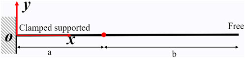
FIGURE 2. Cantilever beam model with a single concentrated mass point.
Bring the boundary conditions into Eq. 6 and Eq. 7 to get Eq. 16, and the final coefficient matrix is given as shown in Eq. 17.
The coefficient matrix Eq. (17) in row-column form must be zero, resulting in the characteristic equation of a simply supported beam with non-uniform mass.
Organize the determinant and get Eq. 19
The same method can be used to derive the eigenvalue matrix equations for simply supported beams and clamped supported beams with a concentrated mass point.
In the simply supported beam model depicted in Figure 3, the boundary conditions at the clamped end and the positions of the concentrated mass point are consistent with those of the cantilever beam. The distinction lies in the boundary conditions at the simply supported end, where deflection and bending moment are both zero, as illustrated in Eq. 20 and 21.

FIGURE 3. Simply supported beam model with a single concentrated mass point.
By introducing the boundary conditions into Eq. 6 and 7 is obtained, and the final coefficient matrix is given as shown in Eq. 22.
The coefficient matrix Eq. 22 in row-column form must be zero, resulting in the characteristic equation of a simply supported beam with non-uniform mass.
In the clamped supported beam model depicted in Figure 4, the boundary conditions at the clamped end and the positions of the concentrated mass point are consistent with those of the cantilever beam. The distinction lies in the boundary conditions at the another clamped supported end. These conditions entail the deflection of 0 and the Rotation of 0, as illustrated in Eq. 24 and 25.
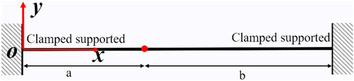
FIGURE 4. Clamped supported beam model with a single concentrated mass point.
By introducing the boundary conditions into Eq. 6 and 7 is obtained, and the final coefficient matrix is given as shown in Eq. 26.
The coefficient matrix Eq. 26 in row-column form must be zero, resulting in the characteristic equation of a simply supported beam with non-uniform mass.
The characteristic Eq. 19 and (23 and Eq. 27 is a nonlinear function of the λ. The Newton-Raphson iteration method can be employed to solve for λ.
Firstly, while ensuring that the total mass and geometric dimensions remain unchanged, the non-uniform mass Bernoulli-Euler beam is equivalently transformed into a uniform mass Bernoulli-Euler beam. Subsequently, the natural frequency of the uniform mass Bernoulli-Euler beam is calculated to obtain an analytical solution. This analytical solution serves as the initial approximate solution (x0) to initiate the iterative process.
Updating the initial guess using the Newton-Raphson iteration formula Eq. 28.
Check whether the new guessed value satisfies the predetermined convergence criteria. If satisfied, consider the root of the equation found; if not, go back to the previous step and repeat the iteration process.
2.2 Theoretical formulations for beam with multiple centralized mass points
The internal filling of the fuel element is complex, and the fuel rod is divided into multiple sections. As shown in Figure 5, the beam model is segmented into N sections with concentrated mass points as endpoints. It is simplified into a Bernoulli-Euler beam with N-1 concentrated mass points, each with a concentrated mass value of
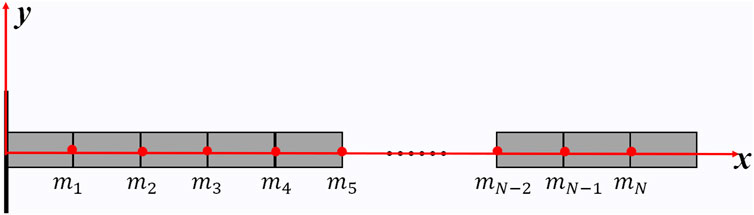
FIGURE 5. Skech of Bernoulli–Euler cantilever beam.
As shown in Eq. (29), it is simplified to the free vibration equation of a Bernoulli-Euler beam with N-1 concentrated masses
where, EI is the bending stiffness of the beam section; A is the beam section area;
The free vibration of the curved beam is a fourth-order partial differential equation. To solve the differential equation, the separation variable method can be employed resulting in Eq. (30):
In the equation,
In this equation,
Consider the Euler beam with concentrated mass as a new system obtained by adding concentrated mass to a uniform mass Euler beam through system modification. The primary mode functions and eigenvalues of this new system can be obtained by perturbation calculations using the mode functions of a uniform mass beam.
In the equation,
Substituting Eqs 32 and 33 into Eq. 29, and simplifying using Eq. 31, yields the expression for Eq. 35:
Substitute Eq. 34 into Eq. 35, then multiply both sides by
Where
Eq. 37 and Eq. 38 can be directly obtained using numerical integration. Letting k = 1, 2, … , η in Eq. 36 yields η nonlinear algebraic equations involving unknowns
Where
Where the i of
The nonlinear matrix Eq. (39) can be solved using the Newton-Raphson method or intelligent algorithms. The Newton-Raphson method is highly dependent on the choice of initial values. Providing reasonable initial values can not only reduce the number of iterations but also achieve more accurate convergence results. Given the meaning of the various combination coefficients within the vector
The termination criteria for iteration can be adopted as follows:
In Eq. 43b: the superscript
3 Benchmark verification of the proposed analytical method
3.1 Single concentrated mass point
By comparing with the natural frequency of the non-uniform mass fuel rod obtained through finite element analysis (FEA) in ANSYS, the correctness of the rapid method is verified.
The finite element model is modeled using beam3 elements. The Beam3 element is a uniaxial element capable of withstanding tension, compression, and bending. Each node of this element has three degrees of freedom: linear displacements along the x and y directions, as well as angular displacement about the Z-axis.
As shown in Figure 6, the finite element model is divided into 17 elements, featuring a concentrated mass point with a mass of M. The lengths of the beams on either side of the concentrated mass are a and b. The key parameters governing the behavior of the system are detailed in Table 1, providing essential insights into the structural dynamics.
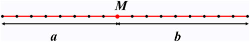
FIGURE 6. Skech of Bernoulli–Euler cantilever beam.
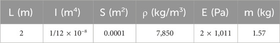
TABLE 1. Main parameters of cantilever beam.
There is a concentrated mass in the middle of the beam (x = 1) with a concentrated mass of 1.57 kg. Under this condition, the relevant parameters in Eq. (19) can be expressed as a = 1, b = 1, M = 1.57kg, EI = 1/6 × 103, and solved Eq. 19 to obtain λn. The calculation results were shown in Table 2.
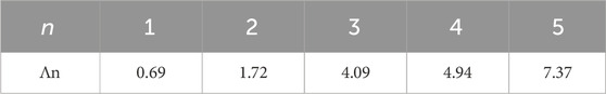
TABLE 2. The value of the first five characteristic roots λ
The natural frequency is calculated by Eq.44b and 45.
The first four natural frequencies were determined using Eq. 44b and 44and the results are presented in Table 3. The theoretical calculations closely align with the simulation results, confirming the accuracy of the formula.
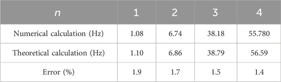
TABLE 3. First 5 natural frequency of beam with single concentrated mass.
To evaluate the sensitivity of the formula to variations in the weight and position of the concentrated mass point, an additional analysis was performed. This involved altering both the location and weight of the concentrated mass point, and the corresponding results are provided in Table 4.
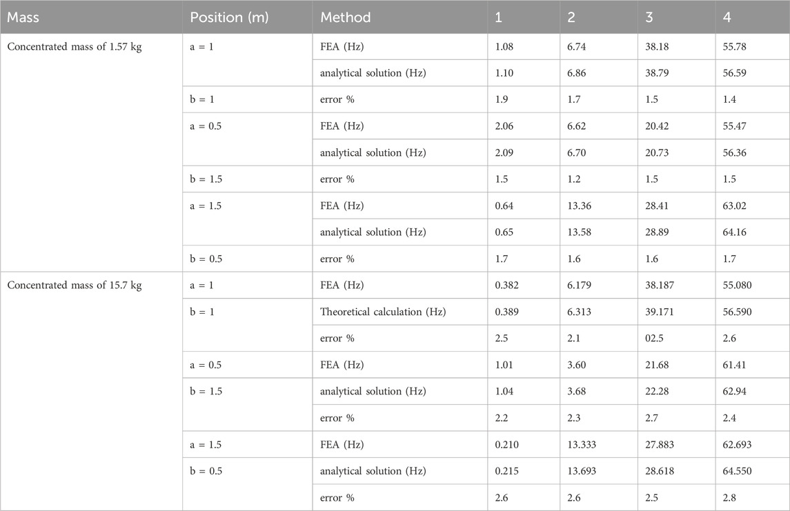
TABLE 4. Natural frequency of single-mass cantilever beam with different mass position.
Eq. 19 is applicable to a cantilever Bernoulli–Euler beam with a single concentrated mass of varying weight. Across different parameter settings, the deviation between the theoretical formula and simulation results is consistently below 3%.
3.2 Multiple concentrated mass points
The parameters of the beam model remain consistent with Section 3.1. Three concentrated mass points are introduced onto the beam, dividing the beam model into four segments. Each concentrated mass has a mass of M, and each segment has a length of 0.25, as shown in Figure 7.
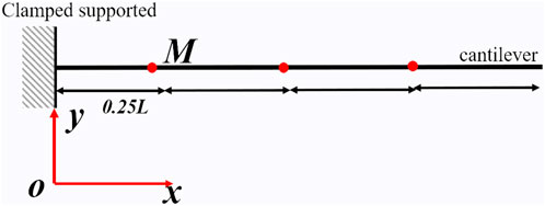
FIGURE 7. The Bernoulli-Euler beam model with three Concentrated mass.
Table 5 presents the first four natural frequency values of the cantilever beam with concentrated mass points calculated using the finite element method and the proposed method. The study investigates the influence of the concentrated mass values on the computational accuracy. From Table 5, it can be observed that the number of concentrated mass points has a limited impact on the calculation error. However, as the weight of the concentrated mass increases, the calculation error also rises. Under various parameter settings, the deviation between the results obtained using Eq. 29 and the ANSYS simulation results is consistently below 3%.
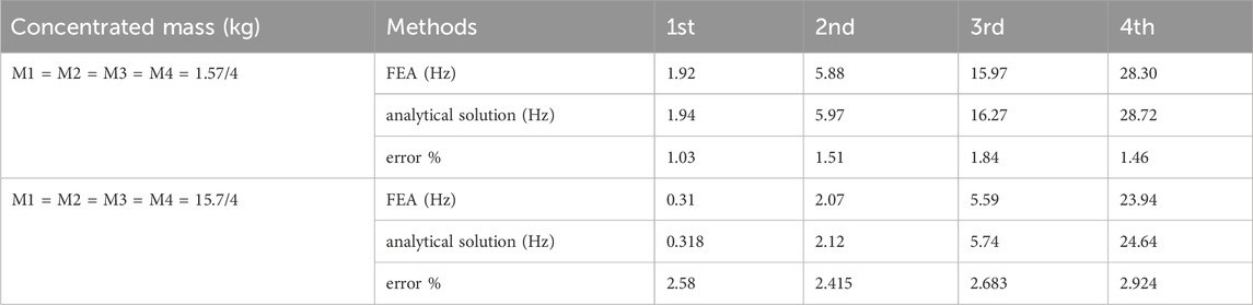
TABLE 5. First 4 natural frequencies of the beam with different concentrated mass points.
To validate the impact of fixation methods on computational accuracy, three different fixation methods are considered (as shown in Figure 8): simply supported beam (CS), cantilever beam (CA) and clamped-supported beam (CC). The mass of concentrated mass point is 1.57/4 kg, and the length is L/4. The parameters of the beam model remain consistent with Section 3.1.

FIGURE 8. The Bernoulli-Euler beam model under different boundary conditions.
Table 6 lists the natural frequencies of non-uniform mass fuel rods under different boundary conditions. After segmenting the fuel rod based on internal filling, the analytical solutions obtained are generally similar to the results obtained through finite element calculations, with errors less than 3%. Among them, the fixed-supported beam has the smallest calculation error, while the cantilever beam has the largest. The stronger the constraint, the smaller the error in the analytical solution. First 4natural frequencies of segmented beams with different fixing methods.
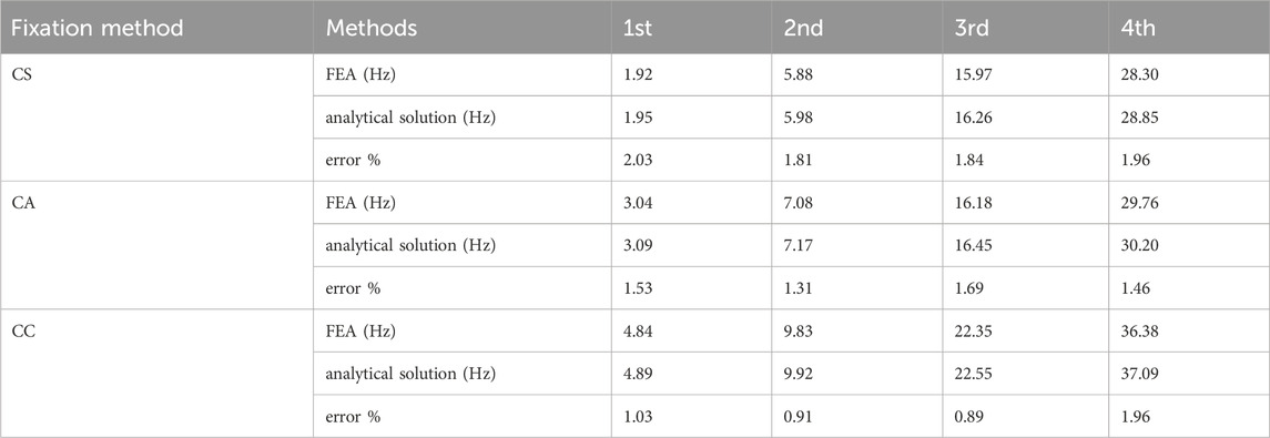
TABLE 6. First 4 natural frequencies of the beam with concentrated mass points under different constraints.
Under various parameter settings, the deviation between the results obtained using the fast method and ANSYS simulation results consistently remains below 3%.
In summary, the model demonstrates accuracy in analyzing both single concentrated mass points and multi-concentrated mass points in the beam.
4 Validation of fast methods in modal analysis of fuel rod
4.1 Structural characteristics of fuel rod
The fuel rod is one of the most important components in a nuclear reactor core. Typically, a fuel rod comprises enriched cylindrical ceramic pellets, gas plenums, and a reflector located at both ends of the fuel rod. These components are sealed within a stainless-steel cladding through the upper and lower end plugs. The length of the internal structure is tailored based on the specific service environment of the fuel rod in different reactors. Figure 9 illustrates the typical structure of fuel rods in a small lead-based reactor. The fuel rod has a length of 850 mm and a diameter of 9.3 mm. The fuel element includes upper and down end plugs, upper and down reflectors, the active zone, and a gas plenum, all enclosed by cladding. The materials, lengths, and masses of each section are detailed in Table 7.
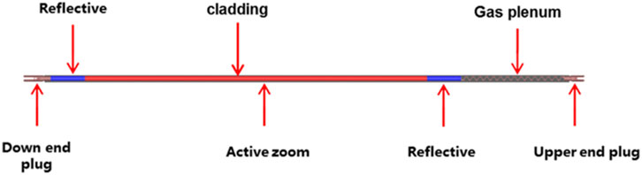
FIGURE 9. Typeical conpostion of fuel rod.
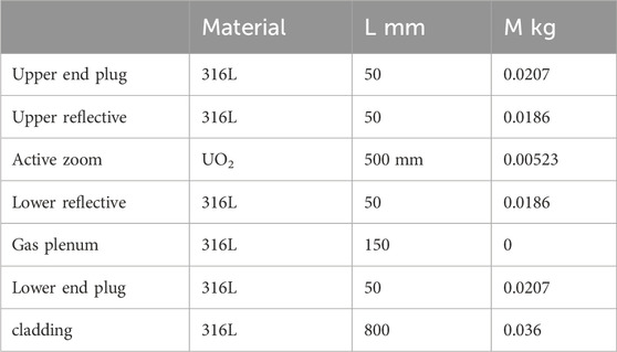
TABLE 7. Type size and mass distribution of fuel rod.
As shown in Figure 10, finite element models for two different constraint methods are established. The finite element model is divided into 17 elements, and the linear density of each element is set based on the distribution of the filling material inside the fuel rod.
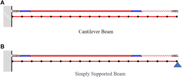
FIGURE 10. Finite element model of fuel rod.
The natural frequency of the fuel rod is determined using the finite rod software ANSYS. In the model analysis, filler is introduced to the beam model in the form of attached mass. The first four natural frequencies of the fuel rod are then calculated using ANSYS, and the results are presented in Table 8.
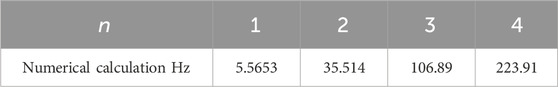
TABLE 8. First fourth natural frequency of non-uniform fuel rod using FEA method.
4.2 Calculation results and analysis
To simplify the internal structure, the contents of the fuel rod are represented as concentrated mass points. This representation allows the fuel rod to be treated as a Bernoulli-Euler cantilever beam, with the concentrated mass points illustrated in Figure 11. The distribution of these concentrated mass points is based on the center-of-gravity of the internal fill.
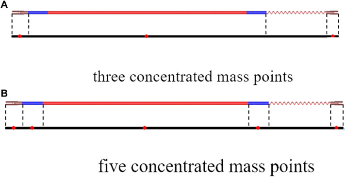
FIGURE 11. Concentrated mass model for analytical method.
Uniform mass distribution (Simplified Model 1): This assumes an even distribution of the filler’s mass within the fuel rod in the beam model. The natural frequency is then calculated using the vibration motion of a uniform mass cantilever beam.
Three concentrated mass points (Simplified Model 2): The internal filling of the fuel rod is organized into three concentrated mass points. The upper-end plug and the gas plenum are considered one concentrated mass point, the active zoom and the reflection are another concentrated mass point, and the lower end plug and the lower reflection form the third concentrated mass point. These mass points are distributed based on the center of gravity.
Five concentrated mass points (Simplified Model 3): Organize the internal filling of the fuel rod into 5 concentrated mass points, considering the upper plug, upper reflective, active zoom, lower end plug, and lower reflective as individual concentrated mass points. These mass points are distributed based on the center of gravity.
The natural frequencies of the three simplified models are presented in Table 9. In comparison with the simplified method using a uniform mass model (Simplified Model 1), the natural frequencies calculated using the new method (Simplified Model 2 and Simplified Model 3) exhibit increased accuracy. As depicted in Figure 12, the number of mass points influences the calculation accuracy with the new method. Setting a greater number of concentrated mass points results in more accurate calculations. For a model with five concentrated mass points, the error is less than 3% when compared with the calculation results obtained using ANSYS.
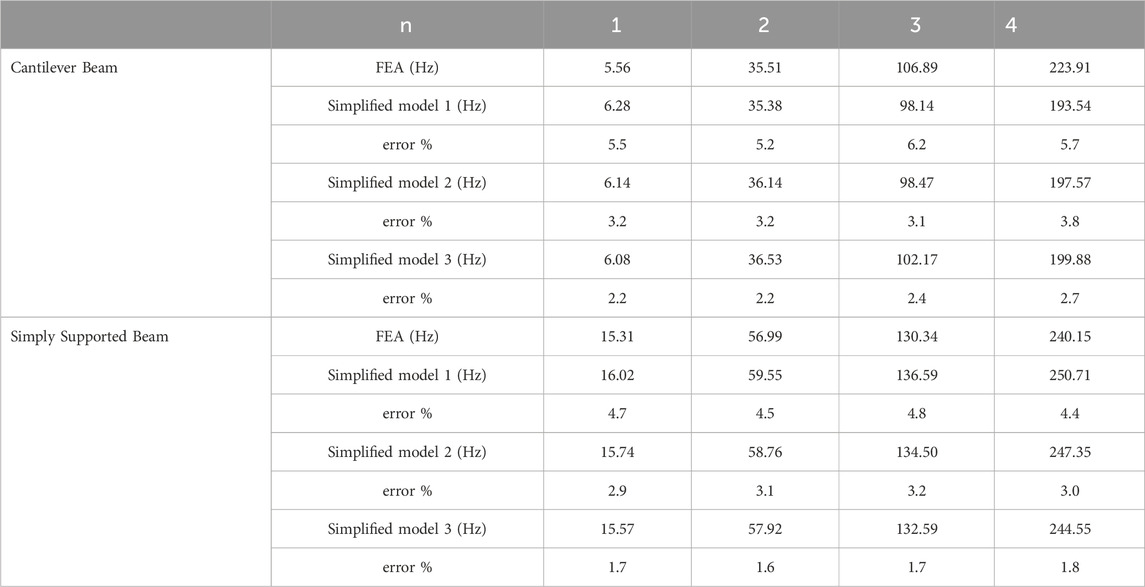
TABLE 9. First fourth natural frequency of fuel rod by FEA method and analytical method.
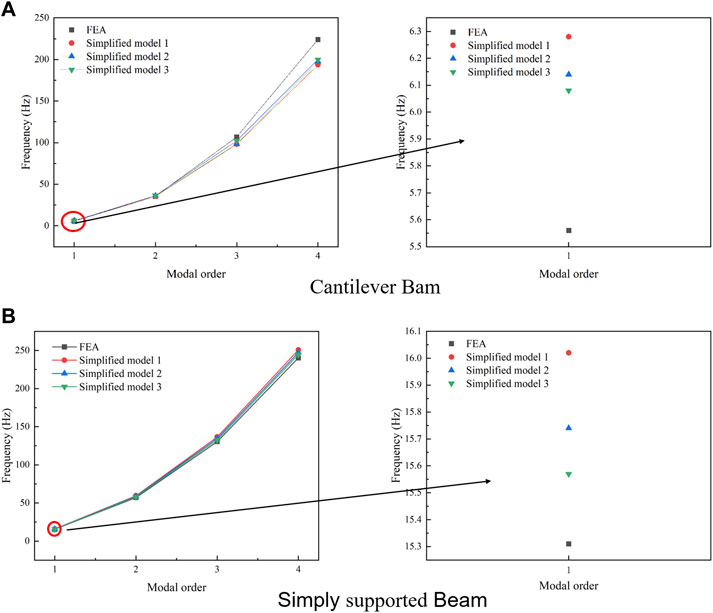
FIGURE 12. First 4 natural frequency using different calculation model.
Moreover, this method demonstrates a faster calculation speed than ANSYS. By utilizing five concentrated mass points, the calculations equivalent to 17 nodes in ANSYS can be efficiently performed. In addition, when there are changes in the structure of the fuel rod, this method eliminates the need for remodeling; instead, it only requires the modification of relevant parameters to complete the modal analysis.
5 The impact of fuel rod structural on natural frequencies
The traditional fixing method for lead-based reactor fuel rods often adopts a configuration where one end is clamped while the other end is simply supported. To minimize the reactor core volume, the fuel rods of small LFR are short and arranged densely. Consequently, the mounting space is small. For ease of installation in a small vessel, the fuel rod is designed with a cantilevered structure, fixed only at the upper end plug rather than employing two-end fixation. In contrast to the traditional fixing method, the natural frequency of the cantilevered structural fuel rod exhibits higher sensitivity to mass distribution.
Lead-based reactor fuel rods have high fuel consumption, requiring longer gas plenums to accommodate fission gas pressure. The gas plenum can result in non-uniform axial distribution of fuel rod mass. The length of the gas plenum is a crucial parameter in the design of fuel rods.
Four fuel rods with different structures are designed (as shown in Figure 13). Figure 13A is a traditional fuel element fixing method with one end clamped and one end simply supported, and the gas chamber is close to the clamped end. Figure 13B is a fixed method for fuel elements with one end clamped and one end simply supported, with the gas chamber located near the simply supported end. Figure 13C is a cantilever fuel rod with one end clamped and one end free, and the gas chamber is close to the clamped end. Figure 13D is a cantilever fuel rod with one end clamped and one end free, and the gas chamber is close to the free end.

FIGURE 13. Different structural models of fuel rods.
5.1 Effect of the gas plenum position on natural frequency
In general, the design lifespan for a fuel rod is typically set at 30 years. The fuel rod has a length of 850 mm and an uneven mass distribution. The weight of the gas pressurization chamber is significantly lighter than the other sections. By analyzing the position of the gas pressurization chamber and considering different constraint methods, the study investigates the impact of mass distribution on the natural frequencies of the fuel rod.
From Table 10 and Figure 14, In the case of fuel rods clamped at one end and simply supported at the other, this is the most commonly used fixing method in current reactors. Due to the asymmetric fixing method, when the gas chamber is near the simply supported end, there is a slight increase in the natural frequency of the fuel rod, with an increase of approximately 7%. This adjustment is made to reduce installation difficulty. In the case of fuel rods clamped at one end and free at the other, forming a cantilever beam structure, the sensitivity of the fuel rod to the position of the gas chamber is significant. When the gas chamber is close to the free end, there is a substantial increase in the natural frequency of the fuel rod, with a maximum increase of up to 17%.
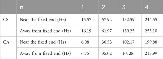
TABLE 10. First fourth natural frequency for differential fuel rods.
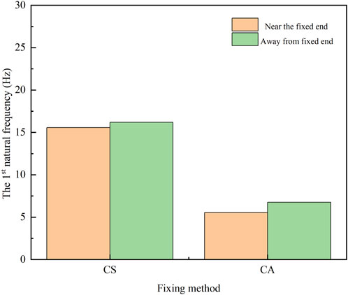
FIGURE 14. Comparison of first frequencies for different structural fuel rod models.
5.2 Effect of the gas plenum length on natural frequency
As the lifespan of the fuel rod increases, it is necessary to increase the length of the gas plenum, to reduce the internal pressure of the fuel rod.
The effect of length on the natural frequency of the fuel rod is determined by varying the length of the gas plenum. The length of the gas plenum is 100mm, 150mm, 200mm, and 250 mm.Four cases with different length were established (In Table 11).
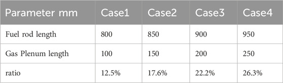
TABLE 11. Structural parameters of different fuel rods.
The first 4 natural frequencies for four scenarios were calculated using the fast computation model. The results are presented in Table 12 and Figure 15.
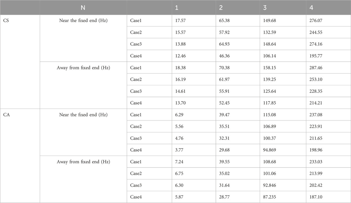
TABLE 12. First fifth natural frequency of differential length fuel rods.
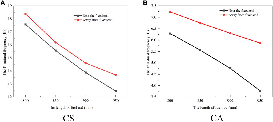
FIGURE 15. First natural frequency of different length fuel rods with fixed and free end.
The research findings indicate a negative correlation between the natural frequency of the fuel rod and the length of the gas chamber. From Figure 15, in the case of clamped one end of the fuel rod and simply supporting the other, as the gas chamber length increases, the influence of the gas chamber position on the natural frequency gradually becomes more pronounced, especially when the gas chamber is close to the clamped end. The rate at which the natural frequency decreases with an increase in length becomes significantly more pronounced. In the scenario where one end of the fuel rod is clamped while the other end is free, this trend is even more noticeable. When the gas chamber length is near the clamped end, the decrease in the natural frequency of the fuel rod becomes more significant with an increase in the gas chamber length.
Therefore, if there is a need to increase the length of the plenum, it is recommended to place the plenum at the free end to enhance the first-order n*/atural frequency.
Compared to traditional fixing methods, the cantilever beam structure of the fuel rod exhibits a significantly lower natural frequency and higher sensitivity to mass, posing certain safety risks. However, the establishment of this fuel rod structure is designed to facilitate in-depth research for optimization.
6 Conclusion
This paper explores the vibration issues of fuel rods with non-uniform mass distribution. We introduce a simplified analytical model to solve the free vibration problem of an Euler-Bernoulli beam with non-uniform mass distribution. The results obtained from this model align well with those computed using ANSYS. Additionally, we analyze the impact of the position and length of the gas plenum on the natural frequency of the fuel rod.
The non-uniform mass distribution in the beam is treated by dividing it into several parts, with concentrated mass points serving as demarcation points. Employing Euler beam theory, the transverse vibration equation is derived for beams with varying mass distribution. Through equivalent means, the non-uniform mass beam is transformed into a multi-segment beam with concentrated mass points, establishing modal function relationships between adjacent uniform segments based on continuous conditions at connection points. The variable coefficient differential equation is then transformed into a nonlinear matrix equation.
The analytical method is validated against a benchmark beam problem, and when compared to fine Finite Element Method (FEM) calculations, it demonstrates high accuracy, approximately 5%. The natural frequency of the fuel rod calculated using the proposed method aligns well with fine FEM results. By simplifying the internal filling of the fuel rod into 5 concentrated mass points, the model’s calculation differs from the finite element model by only 2%, showcasing a significant acceleration in computation speed.
The natural frequency of the fuel rod proves to be highly sensitive to the position of the gas plenum. Specifically, the fuel rod’s natural frequency is higher when the gas plenum is closer to the free end compared to when it is closer to the fixed end, with a notable 17.6% difference in natural frequencies between the two configurations. As the length of the gas plenum increases, the structural stability of the fuel rod with the gas plenum close to the free end becomes more apparent.
The method proposed in this paper has been preliminarily applied to the design analysis of fuel rods and has proven to be highly useful in evaluating the vibration characteristics of fuel rods with non-uniform structural configurations.
Data availability statement
The raw data supporting the conclusion of this article will be made available by the authors, without undue reservation.
Author contributions
GY: Data curation, Formal Analysis, Writing–original draft. YZ: Methodology, Supervision, Writing–review and editing. TF: Validation, Writing–review and editing. YS: Resources, Writing–review and editing. YB: Funding acquisition, Writing–review and editing.
Funding
The author(s) declare that no financial support was received for the research, authorship, and/or publication of this article. This work was supported and funded by National Key Research and Development Plan of China with Grant Nos. 2020YFB1902102 and 2020YFB1901901.
Acknowledgments
The authors would further thank the great help from other members of FDS Consortium in this research.
Conflict of interest
Authors YZ and YB were employed by National Institute of Neutronic Energy Co., Ltd.
The remaining authors declare that the research was conducted in the absence of any commercial or financial relationships that could be construed as a potential conflict of interest.
Publisher’s note
All claims expressed in this article are solely those of the authors and do not necessarily represent those of their affiliated organizations, or those of the publisher, the editors and the reviewers. Any product that may be evaluated in this article, or claim that may be made by its manufacturer, is not guaranteed or endorsed by the publisher.
References
Auciello, N. M., and Nolè, G. (1998). VIBRATIONS OF A CANTILEVER TAPERED BEAM WITH VARYING SECTION PROPERTIES AND CARRYING A MASS AT THE FREE END. J. Sound Vib. 214 (1), 105–119. doi:10.1006/jsvi.1998.1538
Avdoshka, I. V., and Mikhasev, G. I. (2001). Wave packets in a thin cylindrical shell under a non-uniform axial load. J. Appl. Math. Mech. 65 (2), 301–309. doi:10.1016/s0021-8928(01)00034-x
Bailey, C. D. (1978). Direct analytical solutions to non-uniform beam problems. J. Sound Vib. 56 (4), 501–507. doi:10.1016/0022-460x(78)90292-4
Bandini, G., Meloni, P., and Polidori, M. (2011). Thermal-hydraulics analyses of ELSY lead fast reactor with open square core option. Nucl. Eng. Des. 241 (4), 1165–1171. doi:10.1016/j.nucengdes.2010.04.034
BanerjeeSuJackson, J. R. H. D. R. (2006). Free vibration of rotating tapered beams using the dynamic stiffness method. J. Sound Vib. 298 (4-5), 1034–1054. doi:10.1016/j.jsv.2006.06.040
Caruntu, D. I. (1996). On bending vibrations of some kinds of beams of variable cross-section using orthogonal polynomials. Singapore: Springer Nature.
Grape, S., Jacobsson, S., Hellesen, C., Jansson, P., and Åberg Lindell, M. (2014). New perspectives on nuclear power-Generation IV nuclear energy systems to strengthen nuclear non-proliferation and support nuclear disarmament. Energy Policy 73, 815–819. doi:10.1016/j.enpol.2014.06.026
Gupta, A. K. (1985). Vibration of tapered beams. J. Struct. Eng. 111 (1), 19–36. doi:10.1061/(asce)0733-9445(1985)111:1(19)
Hamid, A., Kupschus, P., Malambu, E., Benoit, P., Van Tichelen, K., Arien, B., et al. (2001). MYRRHA: a multipurpose accelerator driven system for research and development. Nucl. Instrum. methods Phys. Res. Sect. A Accel. Spectrom. Detect. Assoc. Equip. 463 (3), 487–494. doi:10.1016/s0168-9002(01)00164-4
Hussein, E. M. A. (2020). Emerging small modular nuclear power reactors: a critical review. Phys. Open, 5, 100038. doi:10.1016/j.physo.2020.100038
OECD Nuclear Energy Agency (2014). OECD nuclear Energy agency for the generation IV international forum, Technology roadmap update for generation IV nuclear Energy systems.
Olver, F. W. J. (1974). Asymptotics and special functions. Introduction to asymptotics and special functions.
Ö, Ö., and Kaya, M. (2006). Flapwise bending vibration analysis of a rotating tapered cantilever Bernoulli–Euler beam by differential transform method. J. Sound Vib. 289, 413–420. doi:10.1016/j.jsv.2005.01.055
Orlov, V. V., Filin, A. I., Lopatkin, A. V., Glazov, A., Sukhanov, L., Volk, V., et al. (2005). The closed on-site fuel cycle of the BREST reactors. Prog. Nucl. Energy 47 (1-4), 171–177. doi:10.1016/j.pnucene.2005.05.017
Ramesh, M. N. V., and Rao, N. M. (2013). Free vibration analysis of pre-twisted rotating FGM beams. Int. J. Mech. Mater. Des. 9 (4), 367–383. doi:10.1007/s10999-013-9226-x
Roberto, P., Andrea, B., Antonio, C., Lorenzi, S., and Luzzi, L. (2014). Object-oriented modelling and simulation for the ALFRED dynamics. Prog. Nucl. Energy 71, 15–29. doi:10.1016/j.pnucene.2013.10.013
Rosa, M. A. D., and Auciello, N. M. (1996). Free vibrations of tapered beams with flexible ends. Comput. Struct. 60 (2), 197–202. doi:10.1016/0045-7949(95)00397-5
Spigler, R., and Vianello, M. (2007). Liouville–Green asymptotic approximation for a class of matrix differential equations and semi-discretized partial differential equations. J. Math. Analysis Appl. 325 (1), 69–89. doi:10.1016/j.jmaa.2006.01.050
Takahashi, M., and Sekimoto, H. (2007). OS8-6 status and prospect of development of lead-alloy-cooled fast reactor. Jpn. Soc. Mech. Eng. 2007.12, 201–204. doi:10.1299/jsmepes.2007.12.201
Wang, M., Lian, C., Li, Y., Wang, Y., Jiang, J., and Wu, Y. C. (2015). Preliminary conceptual design of a lead–bismuth cooled small reactor (CLEAR-SR). Int. J. Hydrogen Energy 40, 15132–15136. doi:10.1016/j.ijhydene.2015.03.097
Wu, Y. C. (2016a). Design and R&D progress of China lead-based reactor for ADS research facility. Engineering 2 (1), 124–131. doi:10.1016/j.eng.2016.01.023
Wu, Y. C. (2016b). CLEAR-S: an integrated non-nuclear test facility for China lead-based research reactor. Int. J. Energy Res. 40 (14), 1951–1956. doi:10.1002/er.3569
Wu, Y. C., Bai, Y. Q., Song, Y., Huang, Q., Zhao, Z., and Hu, L. (2016). Development strategy and conceptual design of China lead-based research reactor. Ann. Nucl. Energy 87, 511–516. doi:10.1016/j.anucene.2015.08.015
Keywords: lead-based fast reactor, fuel rod, free vibration, non-uniform mass, Newton-Raphson iteration method
Citation: Yang G, Zhang Y, Fan T, Song Y and Bai Y (2024) An analytical method for free vibrations of the fuel rod with non-uniform mass of small modular reactor. Front. Energy Res. 12:1374751. doi: 10.3389/fenrg.2024.1374751
Received: 22 January 2024; Accepted: 16 February 2024;
Published: 06 March 2024.
Edited by:
Shichang Liu, North China Electric Power University, ChinaReviewed by:
Hong Zhong, China Institute of Water Resources and Hydropower Research, ChinaShuli Fan, Dalian University of Technology, China
Xunqiang Yin, Dalian University, China
Copyright © 2024 Yang, Zhang, Fan, Song and Bai. This is an open-access article distributed under the terms of the Creative Commons Attribution License (CC BY). The use, distribution or reproduction in other forums is permitted, provided the original author(s) and the copyright owner(s) are credited and that the original publication in this journal is cited, in accordance with accepted academic practice. No use, distribution or reproduction is permitted which does not comply with these terms.
*Correspondence: Yong Zhang, yong.zhang@fds.org.cn