 Yuan Cheng
 Hui Zhang1*
- 1School of Electrical Engineering, Xi’an University of Technology, Xi’an, China
- 2School of Electronics Information, Xi’an Polytechnic University, Xi’an, China
- 3Xi’an Key Laboratory of Interconnected Sensing and Intelligent Diagnosis for Electrical Equipment, Xi’an, China
- 4State Grid Tongchuan Electric Power Supply Company, Tongchuan, China
Modular Multilevel Converter (MMC) is widely used in applications such as High Voltage Direct Current (HVDC) transmission, AC/DC power conversion centers, and large-scale power quality management in electrical grids due to its highly modular structure, strong redundancy and low harmonic content in AC output. The application of the traditional deadbeat predictive current control to MMC enhances the fast tracking ability of the output current, but it still has the problems of low output current accuracy and high dependence on bridge arm inductor. Based on this, this paper proposes an improved two-beat deadbeat synchronous predictive current control based on Newton interpolation method. By improving the two-beat deadbeat synchronous predictive current control strategy, the accuracy of the output current can be further improved and its fast tracking ability can be enhanced. Newton interpolation is introduced to improve the accuracy of the output current while reducing the dependence on the bridge arm inductor. The results show that the control strategy proposed in this paper reduces the output current THD by 2.88% compared with the two-beat deadbeat predictive current control, thus improving the accuracy; the bridge arm inductor value is reduced by 1.28%, thus reducing the dependence; and under the transient environment, the output current can be tracked to its predicted reference value 843 μs in advance, which enhances the fast tracking capability.
1 Introduction
In 2020, in order to face the threat of climate changes and achieve the sustainable development together with the world, the Chinese government put forward the goal and vision of “carbon peak by 2030 and carbon neutrality by 2060" (Yuan et al., 2023). In order to accelerate the realization of this goal, China is building a new type of power system which coexists with multiple new forms of power generation and includes energy storage. Due to its highly modular structure, easy expansion and strong redundancy, MMC converters are currently commonly used in medium and high voltage applications in the industry and have shown good performance. In the new type of power system, MMC converters can not only achieve flexible interconnection of medium and high voltage AC/DC power grids, but also have derived topology for energy storage access. MMC can also be used to participate in energy scheduling, power quality management, and buffer power fluctuations caused by new energy generation in the power grid. This puts higher requirements on the speed of system response and output accuracy.
MMC converters are the same as conventional two and three-level converters in that they are both voltage-source converters (Zheng et al., 2016). The main control system is often used in the dual closed-loop control based on the PI controller (Xu et al., 2019). Although it can achieve independent control of active/reactive power and has good output effect, a double frequency circulation will occur between phases during stable operation, and additional circulation suppressors need to be added to reduce the system loss (Reddy and Shukla, 2020). The introduction of a large number of circulation suppressors causes the complexity of the control system and affects the calculation control time. The feed-forward decoupling of the current inner loop increases the complexity of the control system, and its filter inductor parameters lead to dependence, reduce the output accuracy and stability. Compared with the classic PI controller-based double closed-loop control, some optimized controls, such as model predictive control, internal mode control, sliding mode control, and deadbeat current predictive control, are also used in voltage source converters. The application of two-stage model predictive control to MMC in Ref (Ma et al., 2020). improved the accuracy of AC current tracking, but it is premised on sacrificing greater optimization iteration complexity and computational cost. In Ref. (Yanchao et al., 2015), an internal mode control using the Mrmin criterion for parameter tuning was proposed, which can quickly respond to stabilize the DC-side voltage and improve the robustness of the system when responding to load changes, but when the MMC level and current sampling time change, the current inner loop open-loop transfer function needs to be re-derived, which is not universal. In Ref. (Yang and Fang, 2022), the sliding mode parameters were optimized by introducing the radial basis function RBF neural network algorithm, which does not require any circuit model and controller parameters, and does not affect the performance of the controller when the external environment changes, but the introduction of the RBF neural network algorithm will increase the complexity of the control system.
In recent years, the traditional deadbeat control has been widely used in the industry due to its advantages of simple principle and structure, and strong current tracking ability. In Ref. (Song et al., 2018), the deadbeat control based on Newton interpolation method and power feedforward was applied to the single-phase rectifier, which reduced the dependence on the filter inductor and improves the output current accuracy. Ref (Kang et al., 2017). studied the deadbeat control of photovoltaic grid-connected inverter based on Lagrange interpolation, which reduces the harmonic content of the output current and improves the overall efficiency of the system. In Ref. (Wang et al., 2020), a combination of deadbeat predictive current and model prediction was used to reduce the mismatch of circuit parameters and improve the dynamic response of the system output. The above methods can reduce the dependence on the circuit model, but do not consider the influence of delay on the output of the converter. In Ref. (Chen et al., 2020), the modulation strategy of deadbeat predictive current control and nearest level approximation was adopted, and the selection principle is added to the number of sub-modules in the phase unit, so as to reduce the influence of circulation on the output and improve the accuracy. Ref (Jiang et al., 2017; Ge et al., 2018). reduced the effect of time delay on the output of the converter by predicting the output current of two periods, but the control performance of the converter still depends on accurate circuit model parameters. In Ref. (Chen et al., 2021), the first-order forward difference method is used to predict the output current of two periods to improve the output current accuracy of the active power filter. In Ref. (Abdel-Rady Ibrahim Mohamed and El-Saadany, 2007), Adaptive deadbeat predictive current control with delay compensation is used to reduce the impact of time delay and reduce the dependence on the circuit model. The above methods have the ability of fast tracking of transient current, which reduces the dependence on the circuit model and improves the output accuracy, but does not consider the synchronous prediction of output voltage and output current.
Based on the above, this paper analyzes the time delay of the actual control system. For the MMC output voltage, there exists the time delay of one control period, and for the output current, there exists the time delay of two control periods. In order to compensate for the effect of the time delay on the output accuracy, the output current tracking ability is enhanced while the dependence on the bridge arm inductor is reduced. An innovative MMC improved two-beat deadbeat synchronous predictive current control strategy based on the Newton interpolation method is proposed. The details are as follows:
(1) The first-order forward difference method is used to complete the prediction of one control period of the output voltage, and the improved two-beat deadbeat predictive current control system model is constructed and its mechanism is analyzed. On the basis of retaining the characteristics of traditional deadbeat predictive current control, the introduction of voltage correction improves the accuracy of output.
(2) The Newton interpolation method is used to complete the prediction of the two control periods of the output current, so as to match and improve the two-beat deadbeat predictive current control system model to achieve the purpose of synchronous prediction with the output voltage. The output current tracking capability is enhanced to further improve the accuracy of the output current and reduce the inductor dependence of the bridge arm.
The remaining work of this paper is as follows: Section 1 analyzes the working principle of MMC and establishes the single-phase equivalent circuit model; Section 2 analyzes the traditional deadbeat predictive current control and the time delay of the actual control system; Section 4 simulates and verifies the proposed strategy.
2 MMC working principle and single-phase equivalent circuit modeling
2.1 Main circuit topology and working principle
The MMC main circuit topology is shown in Figure 1A. The three-phase structure is the same, with a total of six bridge arms. Each phase can be divided into upper and lower bridge arms, and each bridge arm is composed of n sub-modules with the same structure cascaded with the bridge arm inductor L. In Figure 1A, Udc is the DC output voltage; uPx and uNx are the output voltages of the upper and lower bridge arms of the x phase, respectively. Phase x = a,b,c; iPx and iNx represent the current flowing through the upper and lower bridge arms of the phase x, respectively; ux is the output voltage of the MMC AC port; usx and ix are AC-side phase voltage and phase current, respectively; Ls is the filter inductor for the energy interaction between the AC power supply and the MMC.
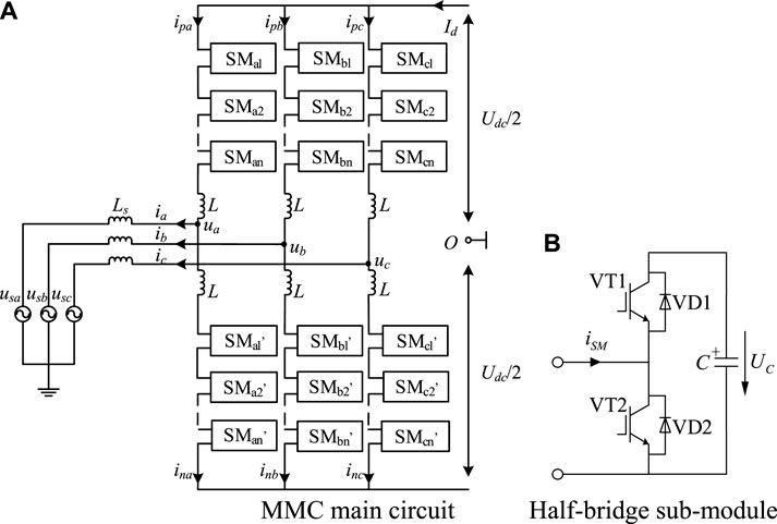
Figure 1. Topology of the MMC main circuit and its sub-modules. (A) MMC main circuit. (B) Half-bridge sub-module.
In this paper, MMC uses a half-bridge sub-module, and the topology is shown in Figure 1B. When running, according to different modulation and sub-module equalization sequencing algorithms, it can work in three states: input, cut-off and latching. When it is running stably, it only works in the state of input and cut-off. The current iSM flowing path and its port voltage uSM are shown in Table 1. 1 and 2 are the outlet ports of the sub-module; in the input state, uSM = Uc; in the cut-off state, uSM = 0.
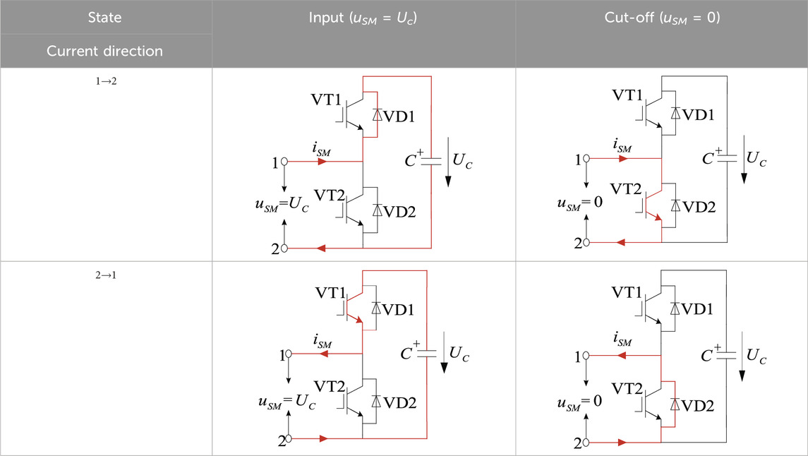
Table 1. Working status of sub-modules.
2.2 Modeling of single-phase equivalent circuits
MMC single-phase equivalent circuit is shown in Figure 2. Ignore the effects of AC power and AC-side filter inductors. Taking a single-phase as an example, the KVL equation is established for the upper and lower bridge arms (Tan et al., 2021):

Figure 2. MMC single-phase equivalent circuit.
The MMC three-phase structure is symmetrical, and the DC-side current is evenly distributed among the three phases. The capacitor voltage of the sub-module of the phase unit fluctuates, resulting in the voltage difference among the phase units, forming a double frequency circulation. Therefore, the interphase circulation icir in this paper includes the DC circulation and the interphase double frequency circulation that are evenly distributed among the three phases. Thereby, the current equations of the single-phase upper and lower bridge arm nodes are established:
The circulation current in the bridge arm current intensifies the fluctuation of the capacitor voltage of the sub-module, resulting in a decrease in the accuracy of the DC output voltage and an increase in the system loss (Bahrani et al., 2016). Therefore, it is necessary to introduce circulation suppression when designing the deadbeat predictive current control system applied to MMC.
3 Delay analysis of traditional deadbeat predictive current control and actual control system
Not only will the circulation affect the accuracy of the output, but the actual control system has a certain delay, which will also affect the accuracy of the system output. Therefore, the innovation proposed in this paper is an improvement on the delay analysis of the traditional deadbeat predictive current control model and actual control system.
3.1 Conventional deadbeat predictive current control applied to MMC
By discretizing formula (1), the formula for the output voltage of the upper and lower bridge arms of the MMC in the kth control period (Zhang et al., 2021) is obtained:
where Udc(k) and ux(k) are the DC-side voltage and the AC-port output voltage in the kth control period, respectively; uPx(k) and uNx(k) are the sum of the voltages of all submodule capacitors of the control cascaded into the upper and lower bridge arms of the MMC main circuit in the kth control period; iPx(k) and iNx(k) are the currents flowing through the upper and lower bridge arms, respectively; i*Px(k+1) and i*Nx(k+1) are the upper and lower bridge arm currents at the beginning of the k+1 control period, that is, the reference values for the prediction of the upper and lower bridge arm currents. According to formula (2), formula (4) can be obtained:
where ix_ref is the AC current reference value; icir_ref is the reference value for interphase circulation to suppress the system circulation and reduce the voltage fluctuation of the capacitor of the sub-module. The interphase circulation reference value icir_ref can be obtained by PI control of the difference between capacitor voltage reference value Uc_ref of the sub-module and its average value Uc_aver.
where kp and ki are proportional and integral coefficients, respectively.
Formula (4) is substituted into formula (3) and formula (5) to construct a deadbeat predictive current control system, as shown in Figure 3. The MMC deadbeat predictive current control system is divided into three parts: voltage outer loop (circulation current suppression), current inner loop (deadbeat predictive current control), carrier phase-shift modulation and sequencing algorithm. The reference value of the interphase circulation is obtained by the voltage outer loop icir_ref and the reference value of the AC current is substituted together with the reference value of the AC current ix_ref into formula (4) to get the reference value of the output current of the upper and lower arms of each phase iPx_ref and iNx_ref. The reference values uPx(k) and uNx(k) of the voltage of the upper and lower bridge arms of each phase in the kth control period can be obtained by substituting iPx_ref and iNx_ref into formula (3). The sub-modules that should be put in the upper and lower bridge arms of each phase are obtained by the carrier phase-shifting modulation and sequencing algorithm, and the trigger pulse of the sub-module of each phase is generated.
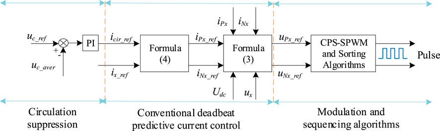
Figure 3. Traditional deadbeat predictive current control applied to MMC.
Note: The uPx_ref and uNx_ref in Figure 3 are uPx(k) and uNx(k) in formula (3)
3.2 Delay analysis of the actual control system
Normally, we want to complete the sampling, computational control, and output of each physical quantity of the system at the same time. However, in the actual control system, there are delays in the process of system sampling, calculation control, and loading duty cycle, which cannot be completed at the same time, so the influence of time delay should be considered when designing the control system (Wang et al., 2015a). Figure 4 is a schematic diagram of the time delay of considering system sampling, calculating control, loading duty cycle, and generating target signals. iPx and iNx were used as the control variables, uPx and uNx were the controlled variables, and Ts was approximately equivalent to the carrier period (i.e., one beat). At the time of kTs, start sampling iPx and iNx; During the control period from kTs to (k+1)Ts, the sampling of iPx and iNx is completed, and the calculation of uPx and uNx is completed. At the time of (k+1)Ts, start loading duty cycle; During the control period from (k+1) Ts to (k+2)Ts, the duty cycle conversion is completed and the voltages of the upper and lower bridge arms of the MMC, uPx and uNx, are output. At the time of (k+2)Ts, the target current (MMC upper and lower arm currents) iPx and iNx can be obtained.

Figure 4. Schematic diagram of delay of the actual control system.
Through the above analysis, it can be seen that there is a delay of one beat between the output voltage uPx and uNx, that is, the delay of one control period Ts from the start time of current sampling to the start time of loading duty cycle. There is a delay of two beats between the output current iPx and iNx, that is, the delay is 2Ts (two beats) between the start time of current sampling and the time when the target current signal is obtained, resulting in a lag in the control effect.
Previous studies have shown that the delay of the control system will reduce the output accuracy, affect the stability, and reduce the follow-up performance (Zhang et al., 2017). Therefore, the delay of the output voltage/current is compensated by the control period at the same time to achieve a good control effect.
4 Improved two-beat deadbeat synchronous predictive current control based on Newton interpolation method
In order to solve the problem of circulation and delay, this paper proposes an improved two-beat deadbeat synchronous predictive current control based on Newton interpolation method. On the basis of the control period plus one of the traditional deadbeat predictive current control model, the first-order forward difference method and Newton interpolation method are introduced to predict the output voltage and output current in one beat and two beats, respectively. Not only can it achieve synchronous prediction, but it can also improve output accuracy and enhance output current tracking ability. Figure 5 shows the technical route for the realization of the control strategy proposed in this paper.
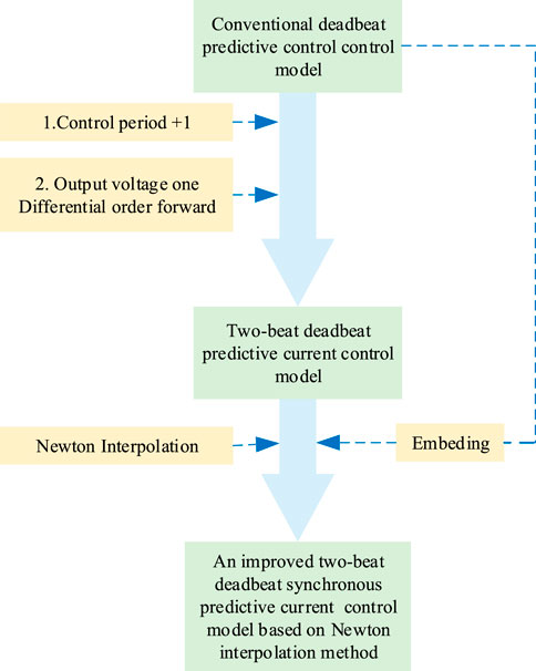
Figure 5. The technical route of the improved two-beat deadbeat synchronous predictive current control based on Newton interpolation method.
4.1 Two-beat deadbeat predictive current control
In order to compensate for the influence of the delay on the control effect, the output voltage of the AC port is predicted one beat in advance, and the output current of the upper and lower bridge arms is predicted two beats in advance, so the control period plus one can be processed for formula (3) to obtain (Zhang et al., 2021):
When the MMC is running stably, the DC voltage fluctuation is relatively small, and it can be considered that:
From formula (3) and formula (6), it can be seen that the output voltage ux of the AC port is a linear relationship with the predicted currents i*Px and i*Nx of the upper and lower bridge arms, and the control period plus one. Since Ts is approximately equivalent to the carrier period, and its value is small, it can be considered that the increments of ux in each control period are equal, and the first-order forward difference method is used to predict and downtime ux, and it can be obtained (Abdel-Rady Ibrahim Mohamed and El-Saadany, 2007):
The predicted reference values of ux in the k+1 control period are:
First, substituting formula (9) into formula (6); Secondly, i*Px (k+1) and i*Nx (k+1) in formula (3) are replaced by iPx (k+1) and iNx (k+1), and the expressions iPx (k+1) and iNx (k+1) are obtained by formula (3) and substituted into formula (6). Finally, in combination with formula (7), formula (10) is obtained:
From formula (10), it can be seen that the mechanism of two-beat deadbeat predictive current control is to add the correction terms of bridge arm inductor voltage and AC-port output voltage on the basis of the traditional deadbeat predictive current control, so as to increase the speed and accuracy of the control system. The traditional deadbeat predictive current control can realize the fast tracking of the bridge arm current, so that the system can run stably. In the actual circuit, the bridge arm inductor current will cause the bridge arm inductor value to change, and the bridge arm inductor voltage correction term can be used to correct this change; Similarly, the AC-port output voltage correction term can be used to correct changes in the grid-side voltage.
4.2 Newton interpolation method and its quadratic/tertiary interpolation polynomials
In order to reduce the dependence of the predicted current of the bridge arm on the inductor of the bridge arm and further improve the accuracy of the control system, in this paper, the Newton interpolation method is used to predict the output current of the bridge arm. There is a series of unequal independent variables (z0,z1,z2…,zn, where m≠n,zm≠zn) and their function f(z). f (zn)-f (zm)/(zn-zm) becomes the first-order difference quotient of the function f(z) at the point zm and zn, which is denoted as f [zn,zm]; f [z1,z2,…,zk]-f [z0,z2,…,zk−1]/(zk-z0) is the k-order difference quotient.
According to the definition of the difference quotient (Zhang et al., 2017), the Newton interpolation first-order polynomial is obtained:
The quadratic polynomial is:
Therefore, the nth degree polynomial of f(z) is:
According to formula (4), the reference value of the bridge arm current prediction is related to the AC current reference value and the circulation reference value, and the circulation reference value can be obtained by the voltage outer loop, so the prediction of the bridge arm current can be converted into the prediction of the AC current reference value. Therefore, the reference values of AC current prediction at (k+1)Ts and (k+2)Ts can be predicted according to formula (13) and the sampling values of AC current at (k-2)Ts, (k-1)Ts and kTs respectively.
Newton interpolation quadratic polynomial is used to establish the AC current prediction expression, shown as follows:
The expression for the prediction of the AC current established by Newton interpolation cubic polynomial is:
Substituting the AC current value at time tk+1 predicted by formula (14) into formula (15), formula (16) can be obtained:
Substituting ix_ref (tk+2) with the ix_ref in formula (4), formula (17) can be obtained:
Substituting formula (17) into formula (10) constructs an improved two-beat deadbeat synchronous predictive current control system based on Newton interpolation method, and the structure is shown in Figure 6.
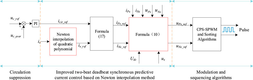
Figure 6. Improved two-beat deadbeat synchronous predictive current control system based on Newton interpolation method.
5 Simulation verification
In order to verify the effectiveness of the improved two-beat deadbeat synchronous predictive current control based on Newton interpolation method, a three-phase 11-level MMC rectifier converter model was built in Matlab/Simulink environment, and the parameters are shown in Table 2. In practical applications, due to the scalability of MMC, more input sub-modules can share the DC voltage in per phase. In this paper, we focus on the rectifier state of MMC: 1) Under steady-state condition, with the goal of stabilizing the DC voltage at 10 kV, compared with the two-beat deadbeat predictive current control, the method proposed in this paper has a less dependence of the output current on the inductor of the bridge arms and achieves higher accuracy. 2) Under transient conditions, the output AC current increases suddenly, and the method proposed in this paper has a faster tracking ability than the two-beat deadbeat predictive current control.
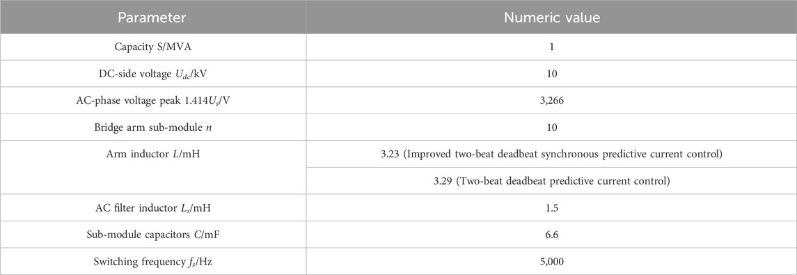
Table 2. System simulation parameters.
5.1 Steady-state conditions
The improved two-beat deadbeat synchronous predictive current control system is applied to MMC, and the DC voltage and current waveforms during stable operation are shown in Figure 7. The two-beat deadbeat predictive current control system is applied to MMC, and Figure 8 shows the DC voltage and current waveforms during stable operation.
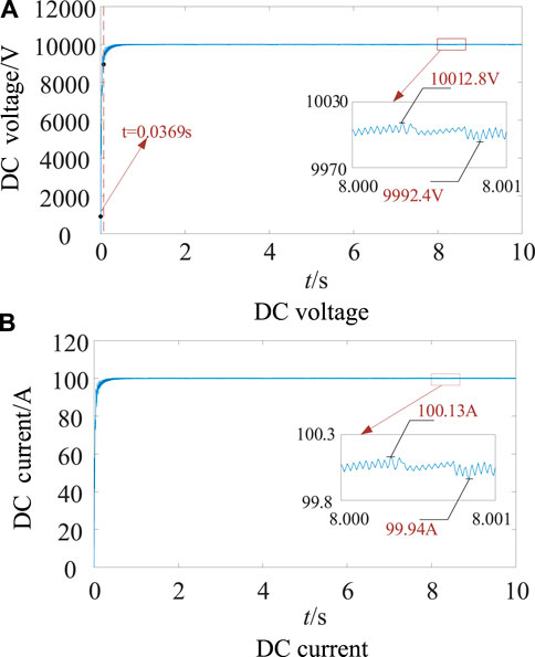
Figure 7. Improved two-beat deadbeat synchronous predictive current control, DC voltage/current. (A) DC voltage. (B) DC current.
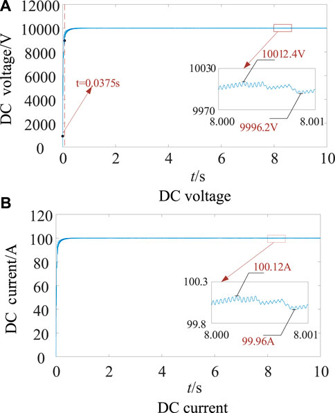
Figure 8. Two-beat deadbeat predictive current control, DC voltage/current. (A) DC voltage. (B) DC current.
As can be seen from the comparison of Figure 7 and Figure 8, both control systems can stabilize the DC voltage at 10 kV and the DC current at 100 A. The two-beat deadbeat synchronous predictive current control is improved, the rise time is 0.0369s, and the steady-state error is about +0.13% and −0.08% at about 3s. In order to stabilize the DC voltage at 10 kV, the inductor value of the bridge arm needs to be set from 3.23mH to 3.29 mH in the simulated environment with the same parameters. The two-beat deadbeat predictive current control has a rise time of 0.0375s and a steady-state error of about +0.12% and −0.04% at about 3s. Table 3 shows the comparison of the above parameters.
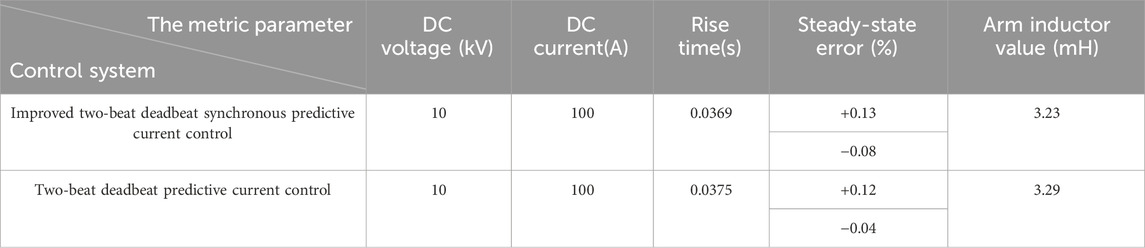
Table 3. Comparison of metric parameters.
Figure 9A is the improved two-beat deadbeat synchronous predictive current control of three-phase AC voltage/current, and the three-phase AC phase voltage peak is 3266 V; the phase current peak is 224.2A, the phase current lag phase voltage is 827 μs, and the power factor cos (14.89°)≈0.9664 is improved. Figure 9B is a two-beat deadbeat predictive current control of three-phase AC voltage/current, and the three-phase AC phase voltage peak is 3266 V; the phase current peak is 228.2A, the phase current lag phase voltage is 965 μs, and the power factor cos (17.37°) ≈ 0.9543.
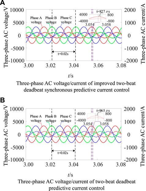
Figure 9. Three-phase AC voltage/current of MMC. (A) Three-phase AC voltage/current of improved two-beat deadbeat synchronous predictive current control. (B) Three-phase AC voltage/current of two-beat deadbeat predictive current control.
Figure 10A shows the total harmonic distortion rate of the AC current in phase A of the improved two-beat deadbeat synchronous predictive current control based on Newton interpolation method. 10 power frequency periods are selected for measurement starting from 3s, and the total harmonic distortion rate is 4.86%. As shown in Figures 10B, 10 power frequency periods are selected for measurement at the same time starting from 3s, and the total harmonic distortion rate is 7.74%. From formula (6) and formula (8), it can be seen that the two-beat deadbeat predictive current control system only uses the first-order forward difference method to predict the output voltage of the AC port for one control period, but formula (6) contains i*Px (k+2) and i*Nx (k+2), so it is necessary to predict the AC current ix for two control periods, therefore, this paper uses Newton interpolation quadratic and cubic interpolation polynomials to predict the AC current for two periods to form i*Px (k+2) and i*Nx (k+2). Under the same system simulation parameters, the inductor of the bridge arm is reduced by 0.06 mH, which reduces the dependence of the predicted current of the bridge arm on the inductor of the bridge arm and improves the accuracy.
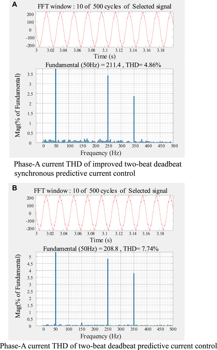
Figure 10. Total harmonic distortion rate of phase-A AC current of MMC. (A) Phase-A current THD of improved two-beat deadbeat synchronous predictive current control. (B) Phase-A current THD of two-beat deadbeat predictive current control.
Table 4 shows the comparison of the THD data of phase-A AC current measured by 10 power frequency periods from 1 to 8s, and Figure 11 shows the data reconstruction curve of Table 4. From the comparison of the data in Table 4, it can be seen that the improved two-beat deadbeat synchronous predictive current control for three-phase AC current THD fluctuates between 4.7% and 4.9%, and the two-beat deadbeat predictive current control for three-phase AC current THD fluctuates between 7.7% and 7.8%.

Table 4. Comparison of phase-A AC current THD of two controls from 1 to 8s.
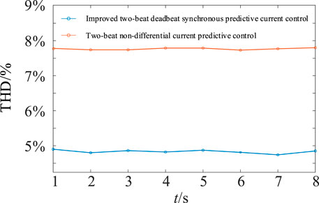
Figure 11. Comparison of phase-A AC current THD for two control.
As shown in Figure 12A, with the improved two-beat deadbeat synchronous predictive current control, the system circulation is gradually decreasing. In the range of 1–8s, the positive peak value of phase A circulation attenuates from 58.24 A to 48.28A, and the circulation inhibition rate is 17.10%. The positive peak value of phase B circulation attenuates from 56.04 A to 46.94A, and the circulation inhibition rate is 16.24%. The positive peak value of phase C circulation attenuates from 61.31 A to 46.49A, and the circulation inhibition rate is 24.17%. As shown in Figure 12B, with the two-beat deadbeat predictive current control, the three-phase circulation is also gradually decreasing. In the range of 1–8s, the positive peak of phase A circulation attenuates from 61.61 A to 42.98A, and the circulation inhibition rate is 30.24%. The positive peak value of phase B circulation attenuates from 58.49 A to 42.59A, and the circulation inhibition rate is 27.18%. The positive peak value of phase C circulation attenuates from 60.14 A to 43.75A, and the circulation inhibition rate is 27.25%. From the above analysis, it can be seen that the circulation of the system is well suppressed by the two control systems, and the effectiveness of the control of the voltage outer loop (circulation suppression) is verified.
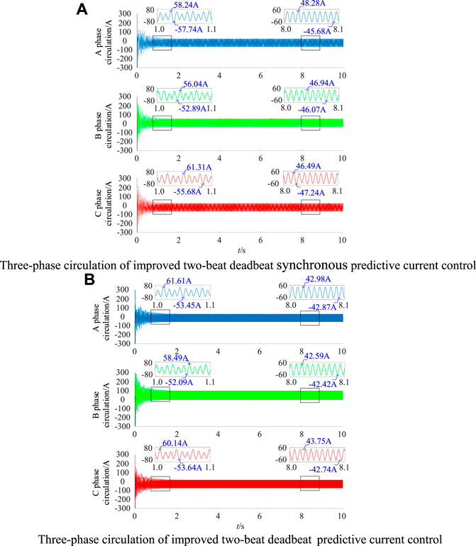
Figure 12. Three-phase circulation of MMC. (A) Three-phase circulation of improved two-beat deadbeat synchronous predictive current control. (B) Three-phase circulation of two-beat deadbeat predictive current control.
Figure 13 shows the capacitor voltage and fluctuation of the MMC Phase-A upper bridge arm sub-modules. Phase A of the improved two-beat deadbeat synchronous predictive current control is shown in Figure 13A. At 1s, the sub-module capacitor voltage fluctuation rate is 2.5%. At 8s, the sub-module capacitor voltage fluctuation rate is 2.9%. The capacitor voltage of phase-A upper bridge arm sub-module of the two-beat deadbeat predictive current control is shown in Figure 13C. At 1s, the sub-module capacitor voltage fluctuation rate is 2.5%. At 8s, the sub-module capacitor voltage fluctuation rate is 2.9%. The analysis shows that the capacitor voltage fluctuation rate of the MMC sub-module meets the requirement of ±10% for both control systems. The effectiveness of the control of the voltage outer loop (circulation current suppression) is indirectly verified.
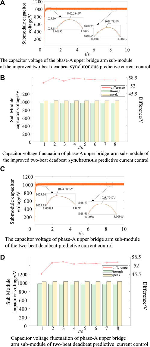
Figure 13. Capacitor voltage and its fluctuation of phase-A upper bridge arm sub-module. (A) The capacitor voltage of the phase-A upper bridge arm sub-module of the improved two-beat deadbeat synchronous predictive current control. (B) Capacitor voltage fluctuation of phase-A upper bridge arm sub-module of the improved two-beat deadbeat synchronous predictive current control. (C) The capacitor voltage of phase-A upper bridge arm sub-module of the two-beat deadbeat predictive current control. (D) Capacitor voltage fluctuation of phase-A upper bridge arm sub-module of two-beat deadbeat predictive current control.
5.2 Transient working conditions
In order to verify the dynamic performance of the two control systems, the transient working conditions are simulated. As can be seen from Figures 14A, B, the improved two-beat deadbeat synchronous predictive current control achieves the peak value of three-phase AC current of 224.2 A before 1s. At 1s, the AC current burst is set, and the output current is tracked to the predicted reference value after 427 μs After entering the steady state, the peak value of the three-phase AC current is 271.5A, and it can be seen from Figures 15A, B that the peak value of the three-phase AC current is 227.8 A before 1s. At 1s, the AC current burst is set, the output current is tracked to the predicted reference value after 1.267 ms. After entering the steady state, the peak value of the three-phase AC current is 273.5 A. Therefore, the method proposed in this paper has better current fast tracking ability than the two-beat deadbeat predictive current control.
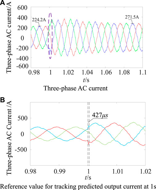
Figure 14. Improved two-beat deadbeat synchronous predictive current control, three-phase AC current burst. (A) Three-phase AC current. (B) Reference value for tracking predicted output current at 1s.
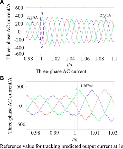
Figure 15. Two-beat deadbeat predictive current control, three-phase AC current burst. (A) Three-phase AC current. (B) Reference value for tracking predicted output current at 1s.
6 Conclusion and prospects
Firstly, the traditional deadbeat predictive current control model is established according to the MMC single-phase equivalent circuit model; secondly, on the basis of analyzing the time delay of the actual control system, the control period plus one, and the two-beat deadbeat synchronous predictive current control model is given by using the first-order forward difference method for the output voltage; thirdly, the traditional deadbeat predictive current control model is embedded into the two-beat deadbeat predictive current control model to complete the improved two-beat deadbeat predictive current control model and its mechanism is analyzed. In order to achieve the purpose of synchronous prediction of output voltage and output current, the Newton interpolation method is used to predict the output current, and its prediction reference value is substituted into the improved two-beat deadbeat synchronous predictive current control model. Finally, the validity of the method proposed in this paper is verified through simulation by comparing it with the two-beat deadbeat predictive current control. After reviewing the work content of this paper, the following work can be carried out in the future (Wang et al., 2015b):
1) According to formula (1) and formula (3) in this paper, the influence of the equivalent internal resistance of the bridge arm is not considered in modeling the traditional deadbeat predictive current control system. In order to further improve the performance of the control system, the combination of the method proposed in this paper and the model predictive control can be considered to further improve the performance of the control system.
2) The carrier phase-shift modulation strategy used in this paper is replaced by the nearest level approximation modulation strategy. The numerator of the rounding function in the nearest level approximation modulation strategy is the voltage modulation wave output by the improved two-beat deadbeat synchronous predictive current control, and the denominator can be a method of equalizing the capacitor voltage and switching frequency of the sub-module. The aim is to ensure the efficiency of the whole machine while making the rounding function in the nearest level approximation modulation strategy more accurate.
Data availability statement
The original contributions presented in the study are included in the article/supplementary material, further inquiries can be directed to the corresponding authors.
Author contributions
YC: Writing–original draft, Writing–review and editing, Validation. HZ: Conceptualization, Funding acquisition, Writing–review and editing. JX: Investigation, Writing–review and editing. ZX: Data curation, Writing–review and editing.
Funding
The author(s) declare that no financial support was received for the research, authorship, and/or publication of this article.
Conflict of interest
Author ZX is employed by State Grid Tongchuan Electric Power Supply Company.
The remaining authors declare that the research was conducted in the absence of any commercial or financial relationships that could be construed as a potential conflict of interest.
Publisher’s note
All claims expressed in this article are solely those of the authors and do not necessarily represent those of their affiliated organizations, or those of the publisher, the editors and the reviewers. Any product that may be evaluated in this article, or claim that may be made by its manufacturer, is not guaranteed or endorsed by the publisher.
References
Abdel-Rady Ibrahim Mohamed, Y., and El-Saadany, E. F. (2007). An improved deadbeat current control scheme with a novel adaptive self-tuning load model for a three-phase PWM voltage-source inverter. IEEE Trans. Industrial Electron. 54 (2), 747–759. doi:10.1109/tie.2007.891767
Bahrani, B., Debnath, S., and Saeedifard, M. (2016). Circulating current suppression of the modular multilevel converter in a double-frequency rotating reference frame. IEEE Trans. Power Electron. 31 (1), 783–792. doi:10.1109/tpel.2015.2405062
Chen, J., Shao, H., and Liu, C. (2021). An improved deadbeat control strategy based on repetitive prediction against grid frequency fluctuation for active power filter. IEEE Access 9, 24646–24657. doi:10.1109/access.2021.3057386
Chen, X., Liu, J., Song, S., and Ouyang, S. (2020). Circulating harmonic currents suppression of level-increased NLM based modular multilevel converter with deadbeat control. IEEE Trans. Power Electron. 35 (11), 11418–11429. doi:10.1109/tpel.2020.2982781
Ge, L., Gu, J., and Wang, C. (2018). Research on grid-connected resonance suppression based on improved photovoltaic. Power Syst. Prot. Control 46 (19), 66–73.
Jiang, W., Lei, WANG, Yan, G., et al. (2017). An improved beat free control method for inner loop current tracking. Proc. CSEE 37 (08), 2370–2383.
Kang, J., Xia, W., and Yang, C. (2017). Lagrangian interpolation method for grid-connected photovoltaic inverter without differential beat. Acta Solar-Energy Sin. 38 (03), 751–757.
Ma, W., Sun, P., Zhou, G., et al. (2020). Predictive control of two-stage model of modular multilevel converter. Power Syst. Technol. 44 (04), 1419–1427.
Reddy, G. A., and Shukla, A. (2020). Circulating current optimization control of MMC. IEEE Trans. Industrial Electron. 68 (4), 2798–2811. doi:10.1109/tie.2020.2977565
Song, Z., Xiong, C., Huang, L., et al. (2018). Power feedforward control of single-phase rectifier based on Newton interpolation. Power Syst. Technol. 42 (11), 3623–3629.
Tan, X., Ren, L., Tang, Y., Li, J., Shi, J., Xu, Y., et al. (2021). Comparative analysis of three types of SFCL considering current-limiting requirement of MMC-HVDC system. IEEE Trans. Appl. Supercond. 31 (8), 1–5. doi:10.1109/tasc.2021.3107816
Wang, J., Song, Y., and Monti, A. (2015b).Design of a high performance deadbeat-type current controller for LCL-filtered grid-parallel inverters. 2015 IEEE 6th International Symposium on Power Electronics for Distributed Generation Systems (PEDG). Aachen, Germany, IEEE, 1–8.
Wang, J., Tang, Y., Lin, P., Liu, X., and Pou, J. (2020). Deadbeat predictive current control for modular multilevel converters with enhanced steady-state performance and stability. IEEE Trans. Power Electron. 35 (7), 6878–6894. doi:10.1109/tpel.2019.2955485
Wang, J., Yan, J. D., Jiang, L., and Zou, J. (2015a). Delay-dependent stability of single-loop controlled grid-connected inverters with LCL filters. IEEE Trans. Power Electron. 31 (1), 743–757. doi:10.1109/tpel.2015.2401612
Xu, Y., Xu, Z., Zhang, Z., and Xiao, H. (2019). A novel circulating current controller for MMC capacitor voltage fluctuation suppression. IEEE Access 7, 120141–120151. doi:10.1109/access.2019.2933220
Yanchao, C., Huang, S., Kong, F., et al. (2015). Steady-state control of MMC-HVDC based on internal mode controller. Power Syst. Technol. 39 (08), 2223–2229.
Yang, X., and Fang, H. (2022). RBF neural network-based sliding mode control for modular multilevel converter with uncertainty mathematical model. Energies 15, 1634. doi:10.3390/en15051634
Yuan, K., Zhang, T., Xie, X., Du, S., Xue, X., Abdul-Manan, A. F., et al. (2023). Exploration of low-cost green transition opportunities for China's power system under dual carbon goals. J. Clean. Prod. 414, 137590. doi:10.1016/j.jclepro.2023.137590
Zhang, Y., Huang, R., Li, H., and Cai, J. (2017). Handling qualities evaluation of time delay and predictive model on teleoperation docking. J. Spacecr. Rockets 54 (4), 936–944. doi:10.2514/1.a33704
Zhang, Y., Yang, X., Pan, Z., et al. (2021). Modular Multilevel Converter improves the predictive control of undifferentiated current. J. Beijing Jiaot. Univ. 45 (06), 43–50.
Keywords: modular multilevel converter, Newton interpolation method, deadbeat predictive current control, dependency, fast tracking
Citation: Cheng Y, Zhang H, Xing J and Xiao Z (2024) An improved two-beat deadbeat synchronous predictive current control strategy for MMC based on Newton interpolation method. Front. Energy Res. 12:1385029. doi: 10.3389/fenrg.2024.1385029
Received: 11 February 2024; Accepted: 25 March 2024;
Published: 17 April 2024.
Edited by:
Liansong Xiong, Xi’an Jiaotong University, ChinaReviewed by:
Leilei Guo, Zhengzhou University of Light Industry, ChinaHao Yi, Xi’an Jiaotong University, China
Jianzhong Xu, North China Electric Power University, China
Copyright © 2024 Cheng, Zhang, Xing and Xiao. This is an open-access article distributed under the terms of the Creative Commons Attribution License (CC BY). The use, distribution or reproduction in other forums is permitted, provided the original author(s) and the copyright owner(s) are credited and that the original publication in this journal is cited, in accordance with accepted academic practice. No use, distribution or reproduction is permitted which does not comply with these terms.
*Correspondence: Hui Zhang, emhhbmdoQHhhdXQuZWR1LmNu