Study on the induced effect of bedding weakness in deep shale gas reservoir on hydraulic fractures propagation
 Guifu Duan1,2
  Jianye Mou
 Zhaoyi Liu
 Lingling Han
- 1College of Petroleum Engineering in China University of Petroleum, Beijing, China
- 2PetroChina Research Institute of Petroleum Exploration and Development, Beijing, China
- 3Northeast Petroleum University, Daqing, China
Shale gas, as an important unconventional oil and gas resource, plays an important role in energy supply. Due to the strong mechanical heterogeneity and compactness, which requires the use of fracturing to crush the formation to obtain industrial production capacity. Therefore, it is very important to analyze shale’s mechanical properties and fracturing propagation laws. In this paper, the shale numerical model is established by adopting discrete element method (DEM). The mesoscopic constitutive parameters of shale with different matrix and bedding strength are determined based on rock samples tests. The reliability of the model is verified by finite element method. And the fracture propagation laws under the influence of shale beddings are studied. The results show that the existence of bedding fractures leads to the nonuniformity of fractures propagation in shale reservoirs. The stress difference of 5 MPa and the approach Angle of 75° are the key factors affecting the interaction between hydraulic fractures and natural fractures. As the bedding number increases, the borehole pressure increases and the total number of fractures’ propagation decreases. The results provide a theoretical basis for further understanding of fractures’ propagation in deep shale reservoirs, and have important guiding significance for optimization and improvement of fracture complexity in the subsequent construction.
1 Introduction
With the development of industry, it is necessary to vigorously develop unconventional resources in order to more effectively ensure the growing demand for energy. Multi stage hydraulic fracturing, as a technology to improve formation flow capacity, has greatly promoted the efficient development of unconventional resources worldwide since the mid-1900s (King, 2010). With the development of this technology, its application areas have expanded from unconventional shale oil and gas extraction to other energy development projects, such as coalbed methane, geothermal energy, and CO2 geological storage (Fang et al., 2020; Ma et al., 2020; Mou et al., 2020; Ren et al., 2020; Fan et al., 2021; Yan et al., 2021). Hydraulic fracturing technology generates artificial fractures through high-pressure fluid drive and interacts with pre-existing natural fractures to effectively increase hydraulic production in low-permeability reservoirs. This can create a high permeability path for reservoir fluids, greatly reducing the cost of unconventional resource extraction (Maxwell and Cipolla, 2011; Warpinski et al., 2013; Zdenek et al., 2014).
There are lots of weak bedding planes and natural fractures developed in unconventional shale reservoirs, which have an inducing effect on the propagation path of fracturing fractures, and thus have a significant impact on the fracturing effect (Heng et al., 2019; Tan et al., 2019; Zhang et al., 2019; Zheng et al., 2020; Heng et al., 2021; Zhao et al., 2021; Cao et al., 2021; Yang et al., 2022). Unlike conventional reservoirs that form symmetrical double wing fracturing fractures, the research goal of shale reservoir transformation is to form complex fracture networks (Liu et al., 2023; Yao et al., 2023; Zhang et al., 2023). Due to the fact that unconventional shale reservoir trans-formation is a complex multi physical field problem involving stress, damage, and seepage, relevant scholars have conducted extensive research, including field and indoor experiments, theoretical derivation, and numerical simulation. When the weak interface includes natural fractures, joints, bedding planes, faults, etc., the existence of the weak interface has a significant impact on the generation and expansion of hydraulic fractures (Warpinski and Teufel, 1987; Hassan et al, 2017; Dong et al., 2021; Liu et al., 2022b). Therefore, the mechanical characterization of weak bedding planes in shale reservoirs and the quantitative analysis of their control over hydraulic fractures are necessary. Foreign countries have invested a lot of effort in studying the laws of natural fractures and hydraulic fractures at Nevada test sites and mining bureaus, with a focus on observing sand supported hydraulic fractures to study their geometric shape and size (Fisher and Warpinski, 2012). Norman et al. (1963) conducted hydraulic fracturing physical model experiments on field outcrops earlier, preliminarily confirming the inducing effect of natural fractures on artificial fracturing. Subsequently, a large amount of experimental researches were conducted both domestically and internationally (Papadopoulos et al., 1985; Chen et al., 2000; Fang et al., 2014; Guo et al., 2014; Zhang et al., 2021; Zhang et al., 2021). Ren et al. (2023) derived the criteria for determining the propagation of three-dimensional hydraulic fractures and natural fractures from the perspective of stress field at the crack tip through theoretical derivation, and verified them through experiments. Li et al. (2022) established a mathematical model for complex fractures in shale gas and simulated the effects of different rock mechanics parameters, stress, fracture parameters, and structural parameters on fracture networks. Although experimental results and theoretical deductions can explain the induction mechanism of natural fractures in hydraulic fracturing, they cannot comprehensively and systematically reflect the fracturing fracture propagation behavior in underground reservoirs under the comprehensive influence of multiple factors. Numerical simulation technology, as an efficient and convenient analytical tool, is widely used in field research to characterize crack morphology and visualize hydraulic fracturing processes. The mainstream numerical analysis methods mainly include finite element method (FEM) (Liu et al., 2022c; Wu et al., 2023; Xue et al., 2023; Zhang et al., 2023), displacement discontinuity method (DDM) (Vandamme et al., 1989; Ali et al., 2019; Cheng et al., 2019; Tang et al., 2019), and particle flow dispersion element method (PFC2D) (Wang et al., 2016; Dou et al., 2020; Wei et al., 2021; Han et al., 2023).
It is advances in fracturing technology and the diversification of analytical methods that have led to the rapid development of unconventional shale oil and gas. Although fracturing technology has achieved great commercial success, some basic mechanisms remain to be further understood due to the diversity of blocks and horizons. For example, in horizontally stratified shale reservoirs, fracture propagation is limited, resulting in unsatisfactory fracturing effect. Compared to mid - shallow shale gas, deep shale gas reservoirs have the engineering characteristics of larger ground stress difference, higher rock strength and higher formation temperature (He et al., 2021). Under the limitation of ground stress and bedding mechanical properties, it is key to carry out the optimization design of fracturing parameters to improve the reconstruction effect. Therefore, it is necessary to further study the fracture propagation mechanism under the influence of heterogeneous shale mechanics. According to the development of deep shale gas in Sichuan Basin, the mechanical properties of rock under the influence of bedding are studied in this paper. Further, on this basis, the simulation analysis of fracture propagation mechanism of reservoir is carried out, which has important guiding significance for effectively carrying out in situ fracturing construction.
2 Geological background
The deep-water shelf facies of the Wufeng - Longmaxi Formation are widely developed in the southern Sichuan Basin (Figure 1) (Ma et al., 2020; Han et al., 2023), with rich organic shale thickness and stable distribution. The southern part of the Yuxi Block and Luzhou Block are located in the sedimentary center of southern Sichuan Basin, and the thickness of high-quality reservoir thickness of Wufeng - Longmaxi Formation ranges from 50 to 70 m. The proportion of deep shale gas resources buried at depths of 3500–4500 m in southern Sichuan reaches 86%, making it the main area for increasing storage and production of deep shale gas in the later stage. The regional structure is mainly located in the low and steep structural belt of southern Sichuan, and the L1 sub section of Longmaxi Formation is the target layer for shale gas exploration and development. Figure 2 shows the characteristics of shale bedding structure and the bedding structure planes observed after core sampling. The significant development of bedding planes in shale reservoirs is bound to have a significant impact on the heterogeneity of rocks, which in turn has a significant impact on rock mechanics and crack propagation in hydraulic fracturing.
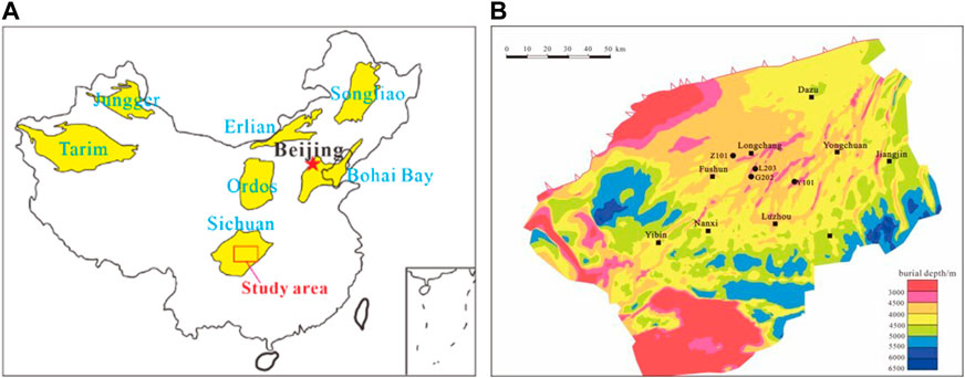
Figure 1. Geological Overview of Sichuan Basin (A) location map; (B) burial depth map.
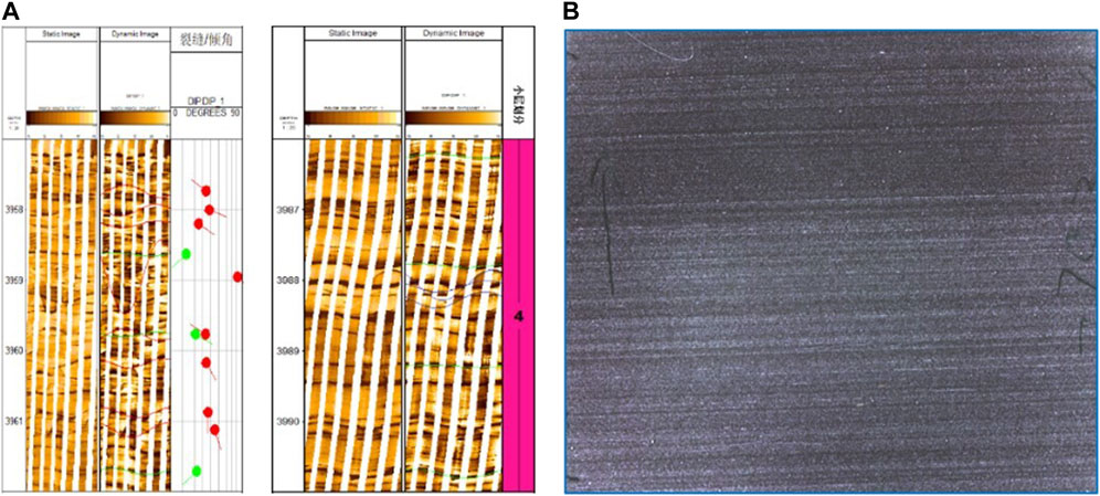
Figure 2. (A) Logging imaging characterization of shale bedding structure; (B) Microscopic bedding planes in the core.
By extracting the mechanism of hydraulic fractures and natural fractures during shale reservoir fracturing, a shale hydraulic fracturing model using the discrete element method can be constructed, as shown in Figure 3.
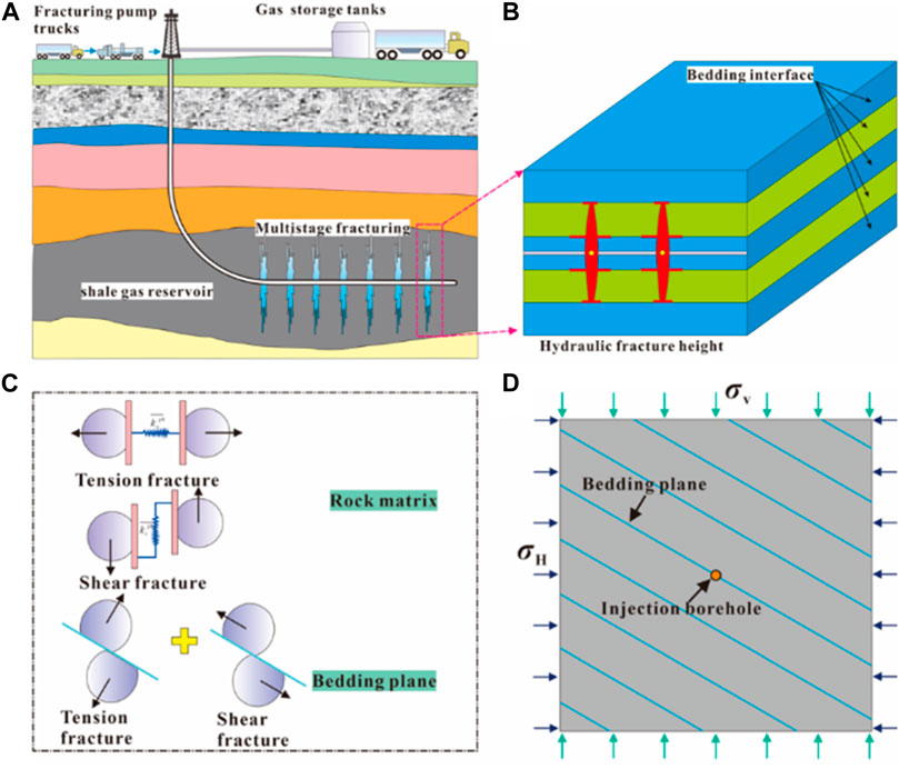
Figure 3. Deep shale fracturing model flowchart (A) field fracturing construction diagram; (B) fracture longitudinal expansion diagram; (C) force - deformation constitutive relationship; (D) shale fracturing model diagram.
3 Hydraulic fracturing simulation model
3.1 Mechanical testing of shale samples
The RTR-1500 triaxial rock mechanics test system was used to test shale mechanics (Figure 4). The axial strain rate was used as servo control throughout the experiment. The experimental strain rate was 0.05%/min and the confining pressure loading rate was 2 MPa/min. The axial stress, axial strain and circumferential strain were simultaneously recorded by the central computer at the same sampling frequency during the whole experiment. Figure 3 shows the experimental rock mechanics test system for shale samples, and the test process conforms to ISRM and ASTM standards (Fairhurst and Hudson, 2000).
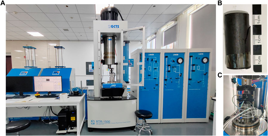
Figure 4. Triaxial compressive rock mechanics tester. (A–C) are the GCTS triaxial compression testing system, shale rock samples used for testing, and rock sample holding tools, respectively.
The stratified shale samples were taken from the Longmaxi Formation in Luzhou block, and were mainly buried between 3500 and 4000 m. In order to consider the influence of different bedding angles, rock tests were carried out at the bedding angles of 0°, 45° and 90° respectively, and the rock breakage results after tests were shown in Figure 5.
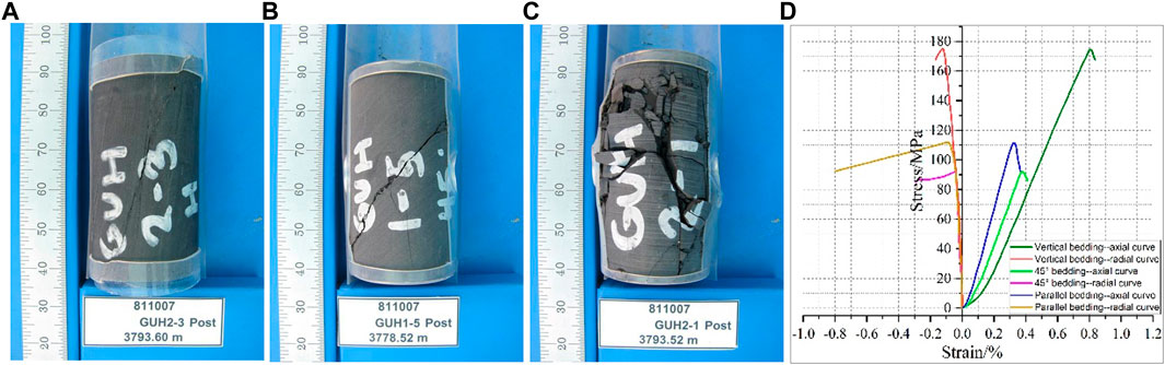
Figure 5. Shale failure morphology and stress-strain relationship curve. (A) Parallel bedding loading; (B) Bedding loading with an angle of 45°; (C) Vertical bedding loading; (D) Loading curves.
The experimental results show that when the loading direction is parallel to the bedding, the fracture of rock breakage mainly expands along the bedding splitting. When the loading direction is perpendicular to the bedding, the fracture of the broken rock appears as block. When the loading direction is at an angle of 45° from the bedding, the rock fractures appear as shear failure along the bedding. Besides, the vertical bedding direction has the highest compressive strength, followed by the parallel bedding direction, and the peak strength corresponding to 45° is the lowest. The Young’s modulus in parallel bedding direction is the highest, followed by 45° bedding Angle, and the vertical bedding is the lowest.
3.2 Numerical model of shale samples
In this paper, the particle flow discrete element is used to construct a shale rock mechanical model. Among them, the particle bonding model (BPM) mainly uses parallel bonding to simulate intergranular rock materials (Potyondy and Cundall, 2004). Parallel bonding can be imagined as a set of springs with constant normal and tangential stiffness uniformly distributed on the contact surface between particles (Fairhurst and Hudson, 2000; Han et al., 2022; Martin et al, 2013). It is defined by the five parameters of normal stiffness, normal strength, tangential stiffness, tangential strength and connection radius, and then characterise the force-deformation behavior of the rock, as shown in Figure 6.
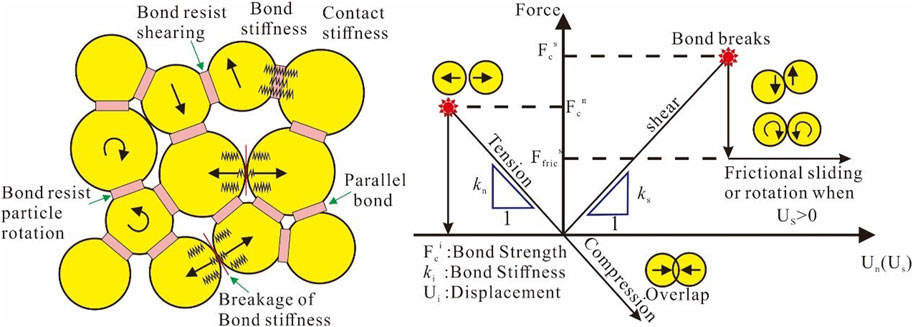
Figure 6. Schematic diagram of the parallel-bond model (Zhou et al., 2017).
The parallel bond model in the BPM model is an elastic beam with a certain size that can divide the total contact force
The strength failure criteria of the tension and shear forces around the parallel bond are:
Where,
A numerical model of shale based on parallel bond model was established to construct meso-mechanical parameters of shale matrix and bedding, and the values of meso-mechanical parameters are shown in Table 1. The fracture shape and peak strength of shale are reduced to the error range of 10% by the Trial-and-error method, which indicates that the mesoscopic constitutive parameters used to characterize shale have good reliability. The shale model and crack morphology are shown in Figure 7, the rock mechanics results are shown in Figure 8, and the error comparison results are shown in Table 2.
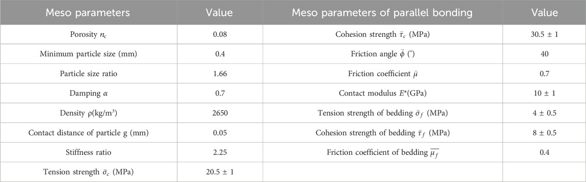
Table 1. Micro-parameters of the fracturing model in PFC2D.
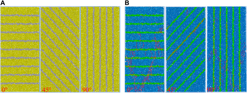
Figure 7. Numerical models of shale with different bedding angles (A) Numerical models; (B) Crack morphology.
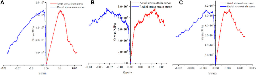
Figure 8. Uniaxial compression curves under the influence of different bedding directions (A) Vertical bedding direction (B) 45° angle bedding direction (C) vertical bedding direction.
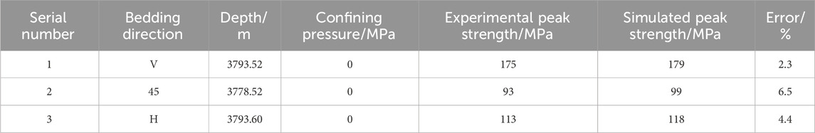
Table 2. Rock mechanics results of deep shale uniaxial test under different bedding angles.
3.3 Numerical model of shale fracturing
In the numerical model, it is assumed that the rock mass (i.e., the basic mineral particles) is impermeable and that incompressible fluids can permeate only through contacts (microcracks). Therefore, the hydrodynamic analysis can be performed as follows: First, the liquid penetrates into the contact point; Then the corresponding fluid pressure is added to the contact, affecting the stress and displacement field around the contact. After that, the contact aperture increases with the increase of fluid pressure. Once the contact failure conditions are met, the initiation or further expansion of micro-cracks will be triggered, resulting in changes in the corresponding stress field, displacement field and fluid pressure in the discrete element model (Zhou et al., 2017). The flow of fluid through the contact and the corresponding crack deformation diagram are shown in Figure 9.
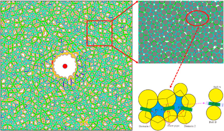
Figure 9. Stress schematic diagram of pipe flow model and discrete element fracturing model.
In the simulation, since it is possible to assume that the fluid flows only in the contact direction, the contact network represents the possible flow network. In Figure 9, the node domain represents the intersection of the flow network, and the green force bond between the two nodes is the flow path. For example, using the cubic law, the flow rate from zone 1 with pressure p1 to zone 2 with pressure p2 can be calculated using the formula (5):
Where,
Equation 5 indicates that even when the fluid pressure in the first and second regions is zero, flow can occur at the contact point due to gravity. In addition, if the saturation of the second domain is zero (i.e., s = 0), it cannot flow from the second domain to the first domain (which means it cannot flow from a completely unsaturated domain to other regions). Once contact occurs and flow occurs, fluid pressure will be generated within the contact area. Within a time step, the new regional pressure can be calculated using the following formula:
Where,
If the new regional pressure calculated by formula (6) is negative, the pressure is set to zero and the saturation is reduced by domain outflow, as shown below.
Where,
In addition, to maintain the numerical stability of the explicit fluid flow algorithm, the time step cannot exceed the following threshold:
The actual contact force
Where,
In the discrete element model, the flow chart of rock deformation and damage caused by fracturing fluid injection is shown in Figure 10.
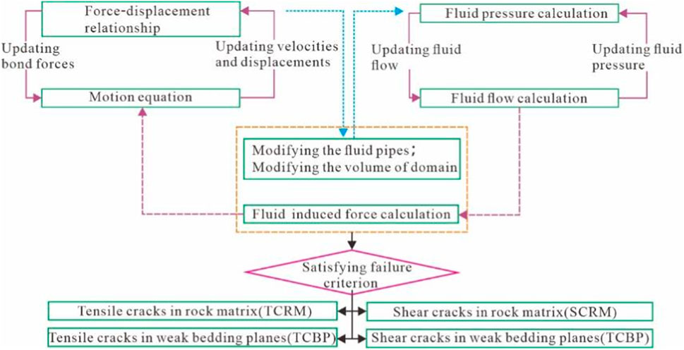
Figure 10. Fluid-solid coupling calculation process of discrete element model (Zhou et al., 2016).
3.4 Model verification
In order to verify the fracturing model’s reliability with DEM, the basic finite element method (FEM) computational model of fluid-solid coupling in early research was verified in this paper (Liu X. Q. et al., 2022).
Figure 11A is the cloud image of fracturing damage results under the fluid-structure coupling model, and Figure 11B is the discrete element model established in this paper. The results show that under the same size and boundary conditions, the fracture results of discrete element fracture are consistent with those of finite element fracture damage, which indicates the reliability of the discrete element model. On this basis, the interaction mechanism between hydraulic fractures and single natural fractures is studied. The discrete element numerical model is shown in Figure 12.
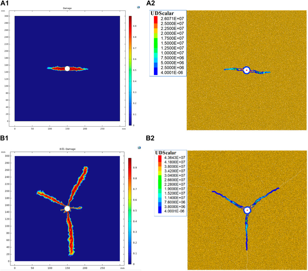
Figure 11. Comparison of fracture results of foundation fracturing. (A1, A2) are the finite element calculation results of COMSOL and the discrete element results of PFC under the effect of 10 MPa geostress difference, respectively; (B1, B2) are the finite element calculation results of COMSOL and the discrete element results of PFC under the effect of 0 MPa geostress difference, respectively.

Figure 12. Schematic diagram of discrete element fracturing model and numerical model.
Figure 13 shows the simulation results of the interaction between hydraulic fractures and natural fractures under different in situ stress differences and fracture approach angles. The pink line segment is the result of hydraulic crack expansion in the matrix, the green line segment is the natural crack activation by shear, and the black part is the original natural crack. Figure 13A shows that hydraulic fractures are easily inhibited by natural fractures (weak surfaces) when they expand along the direction of maximum horizontal stress in the ground stress difference state. Figures 13B, C show that when the fracture approach Angle is large, the activation degree of natural cracks decreases while the penetration phenomenon increases with the increase of in situ stress difference. The interaction chart between hydraulic crack and natural crack is shown in Figure 14.
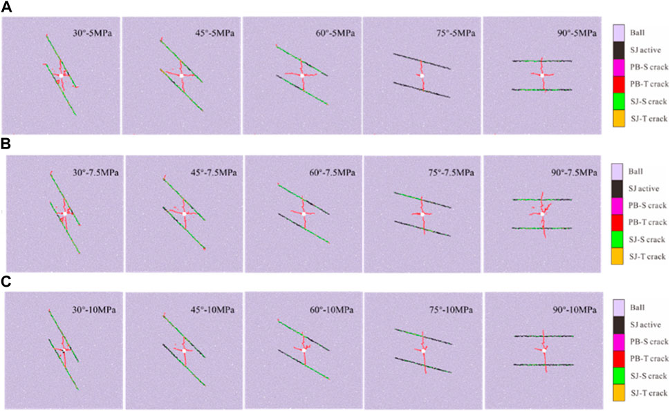
Figure 13. Interaction results between hydraulic fractures and natural fractures (weak bedding surface) under different in situ stress difference and different fracture approach angles (A) The stress difference is 5 MPa (B) The stress difference is 7.5 MPa (C) The stress difference is 10 MPa.
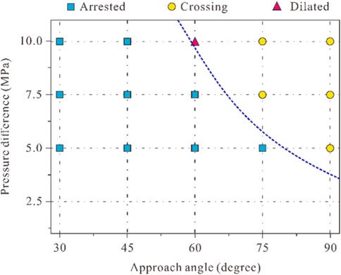
Figure 14. Interaction diagram between hydraulic fractures and natural fractures under different in situ stress difference and fracture approach angle.
According to Figure 13 and Figure 14, it can be concluded that the result of the interaction between the extended hydraulic fracture and the natural fracture (weak plane of bedding) largely depends on the approximation angle of the natural fracture (inside the layer) and the difference of in situ stress. Increasing the natural crack approach angle increases the chance of passing through the natural crack. In addition, increasing the in situ stress difference also increases the likelihood of passing through natural cracks.
4 Results and analysis
In order to study the result of hydraulic fracture propagation under the action of shale bedding, the law of fracture propagation is studied according to bedding inclination angle, ground stress difference and bedding density respectively. Due to the small variation of actual bedding dip angle, horizontal bedding joint is used to analyze the basic model. According to the sensitivity analysis, the bedding dip angle is 0°, 45° and 90°, the ground stress difference is 3MPa, 5 MPa and 10MPa, and the bedding density is 20, 40 and 60. Other parameters remain unchanged, and the calculation results are shown as Figure15, Figure16 and Figure 17.
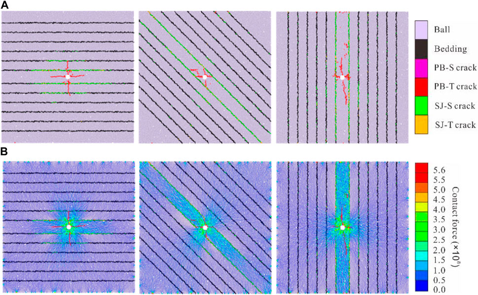
Figure 15. Results of shale fracture propagation under different bedding angles (A) Crack growth results (B) Particle force chain results diagram.
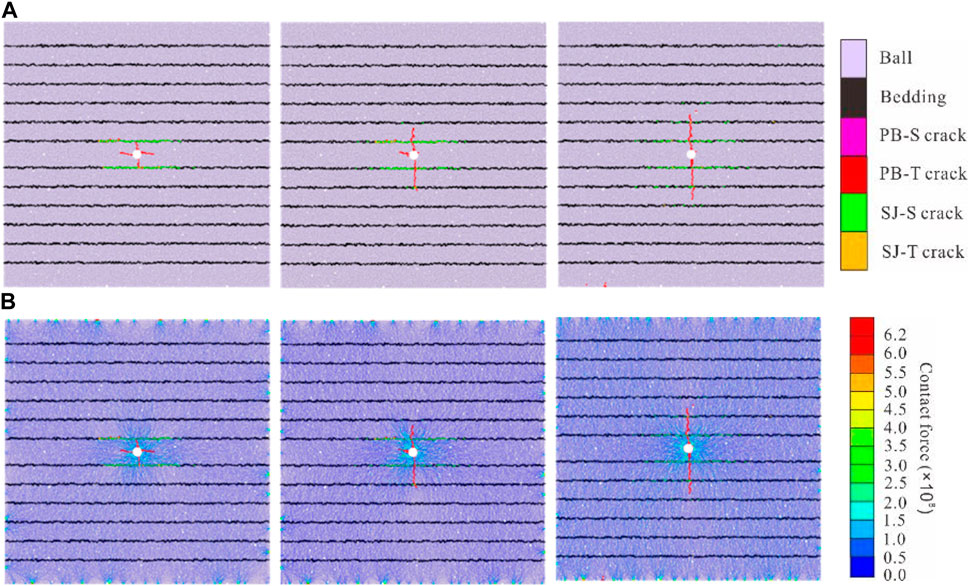
Figure 16. Shale fractures propagation results under different stress differences (A) Crack growth results (B) Particle force chain results diagram.
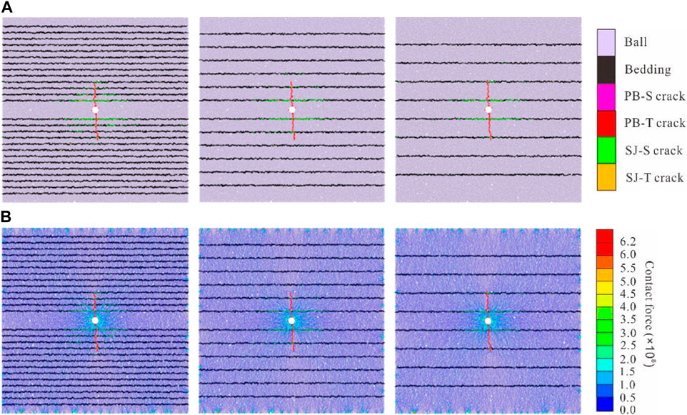
Figure 17. Shale fractures propagation results under different bedding densities (A) Crack growth results (B) Particle force chain results diagram.
The net borehole pressure of fracturing results and the total number of activated cracks were extracted and sorted, and the graph was drawn in Figure 18. The results show that the larger the stress difference is, the faster the total number of cracks increases and the higher the net pressure is. The smaller the bedding dip angle is, the greater the net hole pressure is and the slower the fracture propagation rate is. This indicates that horizontal bedding is not conducive to fracture propagation in the direction of fracture height, while the formation with certain bedding dip angle is more conducive to vertical fracturing reconstruction. The higher the bedding density, the lower the net borehole pressure and the faster the crack growth rate. This is caused by the fact that the weak surface of bedding reduces the fracture energy consumed by fracture propagation, and the bedding is activated and opened rapidly.
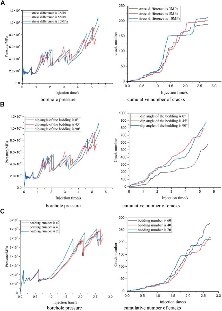
Figure 18. Sensitivity analysis of hydraulic fracture propagation (A) Curves of fracturing simulation results under different stress differences (3 MPa, 5 MPa, 10 MPa) (B) Curves of fracturing simulation results under different dip angle of bedding (0o, 45o, 90o) (C) Curves of fracturing simulation results under different bedding densities (20, 40, 60).
5 Conclusion
In this study, a fluid-solid coupling model based on DEM is developed, and the reliability of the numerical prediction results is demonstrated through interactive verification, and then the induced influence of the shale beddings parameters on the hydraulic fractures networks in the deep shale gas reservoir are discussed. And the results provide a theoretical basis for deep shale fractures’ propagation, and have important guiding significance for improving the optimization of fracture complexity.
1) The results show that when the stress difference is higher than 7.5 MPa and the fracture approach angle is higher than 75°, the hydraulic fracture easily spreads through the bedding joints.
2) The larger the stress difference is, the higher the net pressure is and the faster the total number of microcracks grows.
3) The net wellbore pressure increases with decline of the bedding dip angle and the enlargement of the bedding density.
4) The propagation rate of microcracks is positively correlated with bedding density.
Data availability statement
The original contributions presented in the study are included in the article/Supplementary material, further inquiries can be directed to the corresponding author.
Author contributions
DG: Conceptualization, Data curation, Investigation, Resources, Writing–original draft, Writing–review and editing. MJ: Conceptualization, Investigation, Supervision, Writing–review and editing. LZ: Funding acquisition, Investigation, Methodology, Software, Validation, Visualization, Writing–original draft, Writing–review and editing. HL: Data curation, Formal Analysis, Resources, Software, Visualization, Writing–review and editing. CH: Data curation, Formal Analysis, Writing–review and editing.
Funding
The author(s) declare financial support was received for the research, authorship, and/or publication of this article. The authors acknowledge the support provided by the financially supported by National Key Research and Development Program of China (No. 2023YFF0615402).
Conflict of interest
The authors declare that the research was conducted in the absence of any commercial or financial relationships that could be construed as a potential conflict of interest.
Publisher’s note
All claims expressed in this article are solely those of the authors and do not necessarily represent those of their affiliated organizations, or those of the publisher, the editors and the reviewers. Any product that may be evaluated in this article, or claim that may be made by its manufacturer, is not guaranteed or endorsed by the publisher.
References
Ali, R., Fahd, S., Giorgio, B., and Mohammed, S. (2019). Applications of the fast multipole fully coupled poroelastic displacement discontinuity method to hydraulic fracturing problems. J. Comput. Phys. 399, 108955. doi:10.1016/j.jcp.2019.108955
Cao, W. Z., Betul, Y., Sevket, D., Wei, J., Wolf, K. H., Cai, W., et al. (2021). Fracture behaviour and seismic response of naturally fractured coal subjected to true triaxial stresses and hydraulic fracturing. Fuel 287, 119566. doi:10.1016/j.fuel.2020.119618
Chen, M., Pang, F., and Jin, Y. (2000). Experiments and analysis on hydraulic fracturing by a large-size triaxial simulator. Chin. J. Rock Mech. Eng. 19, 868–872. doi:10.3321/j.issn:1000-6915.2000.z1.010
Cheng, W., Wang, R. J., Jiang, G. S., and Xie, J. Y. (2017). Modelling hydraulic fracturing in a complex-fracture-network reservoir with the DDM and graph theory. J. Nat. gas Sci. Eng. 47, 73–82. doi:10.1016/j.jngse.2017.09.006
Dong, X., Ma, X. F., Yang, H. Q., Liu, Y., and Zhang, Q. Q. (2021). Experimental and numerical simulation of interlayer propagation path of vertical fractures in shale. Front. Energy Res. 9, 797105. doi:10.3389/fenrg.2021.797105
Dou, F. K., Wang, J. G., Leung, C. F., and Ma, Z. G. (2021). The alterations of critical pore water pressure and micro-cracking morphology with near-wellbore fractures in hydraulic fracturing of shale reservoirs. Eng. Fract. Mech. 242, 107481. doi:10.1016/j.engfracmech.2020.107481
Fairhurst, C. E., and Hudson, J. A. (2000). Draft proposed ISRM method for determination of complete rock stress-strain curves by uniaxial compression tests. Chin. J. Rock Mech. Eng. 19 (6), 802–808. doi:10.3321/j.issn:1000-6915.2000.06.025
Fan, S. X., Zhang, D., Wen, H., Cheng, X. J., Liu, X. R., Yu, Z. J., et al. (2021). Enhancing coalbed methane recovery with liquid CO2 fracturing in underground coal mine: from experiment to field application. Fuel 290, 119793. doi:10.1016/j.fuel.2020.119793
Fang, T. G., and Zhang, G. Q. (2014). Laboratory investigation of hydraulic fracture networks in formations with continuous orthogonal fractures. Energy 74 (1), 164–173. doi:10.1016/j.energy.2014.05.037
Fang, T. M., Li, S. J., Zhang, Y. N., Su, Y. L., Yan, Y. G., and Zhang, J. (2021). How the oil recovery in deep oil reservoirs is affected by injected gas types: a molecular dynamics simulation study. Chem. Eng. Sci. 231 (15), 116286. doi:10.1016/j.ces.2020.116286
Fisher, K., and Warpinski, N. (2012). Hydraulic-fracture-height growth: real data. SPE Prod. operations 27 (1), 8–19. doi:10.2118/145949-PA
Guo, T. K., Zhang, S. C., Qu, Z. Q., Zhou, T., Xiao, Y. S., and Gao, J. (2014). Experimental study of hydraulic fracturing for shale by stimulated reservoir volume. Fuel 128 (14), 373–380. doi:10.1016/j.fuel.2014.03.029
Han, L. L., Li, X. Z., Liu, Z. Y., Duan, G. F., Wan, Y. J., Guo, X. L., et al. (2023). Influencing factors and prevention measures of casing deformation in deep shale gas wells in Luzhou block, southern Sichuan Basin, SW China. Petroleum Explor. Dev. 50 (4), 979–988. doi:10.1016/S1876-3804(23)60443-4
Han, L. L., Li, X. Z., Liu, Z. Y., Guo, W., Cui, Y., Qian, C., et al. (2022). Study on rock mechanics characteristics of deep shale in Luzhou block and the influence on reservoir fracturing. Energy Sci. Eng. 11, 4–21. doi:10.1002/ese3.1360
Hassan, F., Md, M. H., and Mohammad, S. (2017). Numerical and experimental investigation of the interaction of natural and propagated hydraulic fracture. J. Nat. Gas Sci. Eng. 37, 409–424. doi:10.1016/j.jngse.2016.11.054
He, X., Li, W. G., Dang, L. R., Huang, S., Wang, X. D., Zhang, C. L., et al. (2021). Key technological challenges and research directions of deep shale gas development. Nat. Gas. Ind. 41 (1), 118–124. doi:10.3787/j.issn.1000-0976.2021.01.010
Heng, S., Li, X. Z., Zhang, X. D., and Li, Z. (2021). Mechanisms for the control of the complex propagation behaviour of hydraulic fractures in shale. J. Petroleum Sci. Eng. 200 (1), 108417. doi:10.1016/j.petrol.2021.108417
Heng, S., Liu, X., Li, X. Z., Zhang, X. D., and Yang, C. H. (2019). Experimental and numerical study on the non-planar propagation of hydraulic fractures in shale. J. Petroleum Sci. Eng. 179, 410–426. doi:10.1016/j.petrol.2019.04.054
King, G. E. (2010). “Thirty years of gas shale fracturing: what have we learned,” in SPE annual technical conference and exhibition. doi:10.2118/133456-MS
Li, Y. (2023). Theoretical and numerical analysis of stress shadow effect between echelon fractures in hydraulic fracturing of double vertical wells. Eng. Fract. Mech. 284, 109238. doi:10.1016/j.engfracmech.2023.109238
Liu, H., Huang, Y. Q., Cai, M., Meng, S. W., and Tao, J. P. (2023). Practice and development suggestions of hydraulic fracturing technology in the Gulong shale oil reservoirs of Songliao Basin, NE China. Petroleum Explor. Dev. 50 (3), 688–698. doi:10.1016/S1876-3804(23)60420-3
Liu, X. Q., Sun, Y., Guo, T. K., Rabiei, M., Qu, Z. Q., and Hou, J. (2022a). Numerical simulations of hydraulic fracturing in methane hydrate reservoirs based on the coupled thermo-hydrologic-mechanical damage (THMD) model. Energy 238, 122054. doi:10.1016/j.energy.2021.122054
Liu, Z. Y., Pan, Z. J., Li, S. B., Zhang, L. G., Wang, F. S., Han, L. L., et al. (2022b). Study on the effect of cemented natural fractures on hydraulic fracture propagation in volcanic reservoirs. Energy 241, 122845. doi:10.1016/j.energy.2021.122845
Liu, Z. Y., Pan, Z. J., Li, S. B., Zhang, L. G., Wang, F. S., Wang, C. H., et al. (2022c). Fracturing optimization design of fractured volcanic rock in songliao basin based on numerical research and orthogonal test. Lithosphere 2022. doi:10.2113/2022/3325935
Ma, X. H., Xie, J., Yong, R., and Zhu, Y. Q. (2020a). Geological characteristics and high production control factors of shale gas reservoirs in Silurian Longmaxi Formation, southern Sichuan Basin, SW China. Petroleum Explor. Dev. 47 (5), 901–915. doi:10.1016/S1876-3804(20)60105-7
Ma, Y. Y., Li, S. B., Zhang, L. G., Liu, S. Z., Liu, Z. Y., Li, H., et al. (2020b). Analysis on the heat extraction performance of multi-well injection enhanced geothermal system based on leaf-like bifurcated fracture networks. Energy 213, 118990. doi:10.1016/j.energy.2020.118990
Martin, P. J., Sch¨, O. N., and Conrad, C. (2013). The orientation and dilatancy of shear bands in a bonded particle model for rock. Int. J. Rock Mech. Min. Sci. 57, 75–88. doi:10.1016/j.ijrmms.2012.07.019
Maxwell, S. C., and Cipolla, C. (2011). What does microseismicity tell us about hydraulic fracturing. SPE Annu. Tech. Conf. Exhib. 4. doi:10.2118/146932-MS
Mou, P. W., Pan, J. N., Wang, K., Wei, j., Yang, Y. H., and Wang, X. L. (2020). Influences of hydraulic fracturing on microfractures of high-rank coal under different in-situ stress conditions. Fuel 287, 119566. doi:10.1016/j.fuel.2020.119566
Norman, L., and Frank, W. J. (1963). The effects of existing fractures in rocks on the extension of hydraulic fractures. J. Petroleum Technol. 15 (2), 203–209. doi:10.2118/419-PA
Papadopoulos, J. M., Narendran, V. M., and Cleary, M. P. (1983). “Laboratory simulations of hydraulic fracturing,” in SPE Low permeability gas reservoirs symposium, Denver, Colorado, 14–16.March
Potyondy, A. D. O., and Cundall, P. A. (2004). A bonded-particle model for rock. Int. J. Rock Mech. Min. Sci. 41 (8), 1329–1364. doi:10.1016/j.ijrmms.2004.09.011
Ren, L., Jiang, H., Zhao, J. Z., Lin, R., Wang, Z. H., and Xu, Y. (2022). Theoretical study on fracture initiation in deep perforated wells with considering wellbore deformation. J. Petroleum Sci. Eng. 211, 110141. doi:10.1016/j.petrol.2022.110141
Ren, X. Y., Zhou, L., Zhou, J. P., Lu, Z. H., and Su, X. P. (2020). Numerical analysis of heat extraction efficiency in a multilateral-well enhanced geothermal system considering hydraulic fracture propagation and configuration. Geothermics 87, 101834. doi:10.1016/j.geothermics.2020.101834
Tan, P., Pang, H. W., Zhang, R. X., Jin, Y., Zhou, Y. C., Kao, J. W., et al. (2019). Experimental investigation into hydraulic fracture geometry and proppant migration characteristics for southeastern Sichuan deep shale reservoirs. J. Petroleum Sci. Eng. 184, 106517. doi:10.1016/j.petrol.2019.106517
Tang, H. Y., Wang, S. H., Zhang, R. H., Li, S. B., Zhang, L. H., and Wu, Y. S. (2019). Analysis of stress interference among multiple hydraulic fractures using a fully three-dimensional displacement discontinuity method. J. Petroleum Sci. Eng. 179, 378–393. doi:10.1016/j.petrol.2019.04.050
Vandamme, L., Detournay, E., and Cheng, A. D. (1989). A two-dimensional poroelastic displacement discontinuity method for hydraulic fracture simulation. Int. J. Numer. Anal. Methods 13 (2), 215–224. doi:10.1002/nag.1610130209
Wang, T., Hu, W. R., Elsworth, D., Zhou, W., Zhou, W. B., Zhao, X. Y., et al. (2016). The effect of natural fractures on hydraulic fracturing propagation in coal seams. J. Petroleum Sci. Eng. 2016. 180–190. doi:10.1016/j.petrol.2016.12.009
Warpinski, N., and Teufel, L. W. (1987). Influence of geologic discontinuities on hydraulic fracture propagation (includes associated papers 17011 and 17074). J. Petroleum Technol. 39 (2), 209–220. doi:10.2118/13224-PA
Warpinski, N. R., Mayerhofer, M. J., Agarwal, K., and Du, J. (2012). Hydraulic fracture geomechanics and microseismic source mechanisms. ATCE 18, 766–780. doi:10.2118/158935-PA
Wei, S. J., and Tomac, I. (2022). Numerical evaluation of Failure Assessment Diagram (FAD) for hydraulic fracture propagation in sandstone. Eng. Fract. Mech. 263, 108311. doi:10.1016/j.engfracmech.2022.108311
Wu, L., Hou, Z. M., Xie, Y. C., Luo, Z. F., Xiong, Y., Cheng, L., et al. (2023). Fracture initiation and propagation of supercritical carbon dioxide fracturing in calcite-rich shale: a coupled thermal-hydraulic-mechanical-chemical simulation. Int. J. Rock Mech. Min. Sci. 167, 105389. doi:10.1016/j.ijrmms.2023.105389
Xue, Y., Liu, S., Chai, J. R., Liu, J., Ranjith, P. G., Cai, C. Z., et al. (2023). Effect of water-cooling shock on fracture initiation and morphology of high-temperature granite: application of hydraulic fracturing to enhanced geothermal systems. Appl. Energy 337, 120858. doi:10.1016/j.apenergy.2023.120858
Yan, H., Zhang, J. X., Li, B. Y., and Zhu, C. L. (2021). Crack propagation patterns and factors controlling complex crack network formation in coal bodies during tri-axial supercritical carbon dioxide fracturing. Fuel 286, 119381. doi:10.1016/j.fuel.2020.119381
Yang, H. Z., Wang, L., Yang, C. H., Guo, Y. T., Guo, W. H., Bi, Z. H., et al. (2022). Visualization and quantitative statistics of experimental hydraulic fracture network based on optical scanning. J. Nat. gas Sci. Eng. 105, 104718. doi:10.1016/j.jngse.2022.104718
Yao, Y. D., Wang, L., Wang, K. J., Adenutsi, C. D., Wang, Y., and Feng, D. (2023). A novel high-dimension shale gas reservoir hydraulic fracture network parameters optimization framework. Geoenergy Sci. Eng. 229, 212155. doi:10.1016/j.geoen.2023.212155
Zdenek, P., Marco, S., Viet, T. C., and Zubelewicz, A. (2014). Why fracking works? J. Appl. Mech. Trans. ASME. 81, 101010. doi:10.1115/1.4028192
Zhang, B., Guo, T. K., Qu, Z. Q., Wang, J. W., Chen, M., and Liu, X. Q. (2023a). Numerical simulation of fracture propagation and production performance in a fractured geothermal reservoir using a 2D FEM-based THMD coupling model. Energy 273, 127175. doi:10.1016/j.energy.2023.127175
Zhang, H. Y., Chen, J. B., Zhao, Z. Y., and Qiang, J. L. (2023b). Hydraulic fracture network propagation in a naturally fractured shale reservoir based on the "well factory" model. Comput. geotechnics 153, 105103. doi:10.1016/j.compgeo.2022.105103
Zhang, J., Li, Y. W., Pan, Y. S., Wang, X. Y., Yan, M. S., Shi, X. D., et al. (2021a). Experiments and analysis on the influence of multiple closed cemented natural fractures on hydraulic fracture propagation in a tight sandstone reservoir. Eng. Geol. 281, 105981. doi:10.1016/j.enggeo.2020.105981
Zhang, Q., Zhang, X. P., and Sun, wei. (2021b). A review of laboratory studies and theoretical analysis for the interaction mode between induced hydraulic fractures and pre-existing fractures. J. Nat. gas Sci. Eng. 86 (1), 103719. doi:10.1016/j.jngse.2020.103719
Zhang, R. X., Hou, B., Han, H. F., Fan, M., and Chen, M. (2019). Experimental investigation on fracture morphology in laminated shale formation by hydraulic fracturing. J. Petroleum Sci. Eng. 177, 442–451. doi:10.1016/j.petrol.2019.02.056
Zhao, Y. X., and Liu, B. (2021). Deformation field and acoustic emission characteristics of weakly cemented rock under brazilian splitting test. Nat. Resour. Res. 30 (May), 1925–1939. doi:10.1007/s11053-020-09809-x
Zheng, H., Pu, C. S., and Sun, C. (2020). Numerical investigation on the hydraulic fracture propagation based on combined finite-discrete element method. J. Struct. Geol. 130, 103926. doi:10.1016/j.jsg.2019.103926
Zhou, J., Zhang, L. Q., Pan, Z. J., and Han, Z. H. (2016). Numerical investigation of fluid-driven near-borehole fracture propagation in laminated reservoir rock using PFC2D. J. Nat. gas Sci. Eng. 36, 719–733. doi:10.1016/j.jngse.2016.11.010
Keywords: discrete element method, numerical simulation, deep shale gas, hydraulic fracturing, bedding
Citation: Duan G, Mou J, Liu Z, Han L and Cui H (2024) Study on the induced effect of bedding weakness in deep shale gas reservoir on hydraulic fractures propagation. Front. Energy Res. 12:1392298. doi: 10.3389/fenrg.2024.1392298
Received: 27 February 2024; Accepted: 27 March 2024;
Published: 18 April 2024.
Edited by:
Simeone Chianese, University of Campania Luigi Vanvitelli, ItalyReviewed by:
Gang Lei, China University of Geosciences Wuhan, ChinaDujie Zhang, Sinopec Research Institute of Petroleum Engineering (SRIPE), China
Copyright © 2024 Duan, Mou, Liu, Han and Cui. This is an open-access article distributed under the terms of the Creative Commons Attribution License (CC BY). The use, distribution or reproduction in other forums is permitted, provided the original author(s) and the copyright owner(s) are credited and that the original publication in this journal is cited, in accordance with accepted academic practice. No use, distribution or reproduction is permitted which does not comply with these terms.
*Correspondence: Jianye Mou, 1812262772@qq.com