Compensation characterization of the UPQC system under an improved nonlinear controller based on the MSTOGI-PLL device
 Yuting Yu
 Dan Li1*
 - 1Hunan Railway Professional Technology College, Zhuzhou, Hunan, China
- 2School of Electrical Engineering, College of Engineering, Universiti Teknologi MARA, Shah Alam, Malaysia
- 3Hunan Vocational College of Railway Technology, Zhuzhou, Hunan, China
To solve the delay problem of a unified power quality conditioner (UPQC) system during the separation of the fundamental positive-order components and to better filter out the DC and harmonic components to realize accurate phase locking, a mixed second- and third-order generalized integrator phase-locked loop (MSTOGI-PLL) has been designed to replace the traditional synchronous reference frame phase-locked loop (SRF-PLL). Under the premise of adopting the new phase-locking device of MSTOGI-PLL, the active disturbance rejection control (ADRC) controller or the super-twisting algorithm (STA) sliding mode controller is used in the DC voltage control module instead of the traditional PI controller, and the suitability of the two nonlinear controllers with the MSTOGI-PLL device is investigated. First, the new MSTOGI-PLL device is designed, and the new phase-locking method is applied to make the UPQC realize accurate phase locking under the non-ideal situation of the grid voltage containing unbalance, DC component, harmonics, and so on. Based on the above foundation, the ADRC or STA controller is independently adopted to replace the PI controller to construct the UPQC system with the ADRC + MSTOGI phase-locking device and the second-order STA + MSTOGI phase-locking device. Finally, a simulation comparison is carried out in a Simulink simulation platform regarding the UPQC system under different phase-locking devices, and the simulation results demonstrate that MSTOGI-PLL can successfully filter out the DC component and resolve the phase-locking process delay issue. Additionally, the UPQC system with ADRC + MSTOGI-PLL exhibits superior immunity and response speed to the PI controller and the second-order STA controller.
1 Introduction
With the wide application of nonlinear power electronic devices, harmonics, unbalance, frequency fluctuations, and other problems are becoming more and more serious, and these power quality problems (Lin, 2014) will affect the normal operation of Chinese communications and financial, medical, and other systems. To address these issues, power quality regulation devices, such as static var compensator (SVC) (Tang et al., 2024), dynamic voltage restorer (DVR) (Gao et al., 2023), and active power filter (APF) (Zhang et al., 2017), have emerged, which can only solve a single power quality problem. Based on the APF, Japanese scholars proposed the concept of a unified power quality conditioner (UPQC) (Fujita and Akagi, 1996), which combines the functions of DVR and APF and can compensate for multiple power quality problems simultaneously (Wei et al., 2019; Han et al., 2022; Elik and Ahmed, 2023; Lakhdar et al., 2023). How to control the UPQC to better compensate for power quality is currently a significant area of research among scholars.
Phase-locked loops are typically employed in the large-scale development of new energy production to phase lock the phase and frequency of the fundamental wave components of the grid to ensure synchronization with the grid side and an efficient and high-quality grid connection of inverters. When compensating for voltage and power flow in the series–parallel side of the UPQC, it is necessary to obtain accurate phase information on the grid side, and whether the phase-locking device can output accurate phase-locking results will directly affect the compensation effect of the UPQC. Currently, in UPQC systems, a low-pass filter (LPF) is usually used to eliminate the interference of the AC component in the dq coordinate system, but the use of an LPF with a lower cutoff frequency introduces a serious detection delay problem (Lv et al., 2012). For this purpose, a second-order generalized integrator (SOGI) can be used to solve the delay problem (Nasrollahi et al., 2022; Setiawan et al., 2023), but this phase-locking device is very sensitive to the frequency variation of the input signal, and the results will vary directly with the frequency of the input signal. The standard SOGI was reconfigured, and a better type I SOGI was created by (Li et al., 2024); however, the device is subject to the DC component and, hence, an amount of error. The drawbacks of a type I SOGI are addressed by Shi et al. (2022) by creating an enhanced type II SOGI, which is vulnerable to interference from the high-frequency component, by creating a negative feedback channel for the DC component. A synchronous reference frame phase-locked loop (SRF-PLL) can lock the phase quickly and accurately under an ideal voltage environment, but the SRF-PLL encounters inaccurate phase-locking in the presence of imbalances such as distortions and harmonics in the power grid (Kumar et al., 2022; Pan et al., 2023). To overcome the above defects, experts proposed a decoupled double synchronous reference frame PLL (DDSRF-PLL) (Achlerkar and Panigrahi, 2022; Su et al., 2022), and the low bandwidth filter in this phase-locked loop still causes some delay to the system. For this reason, this study proposes the use of a new mixed second- and third-order generalized integrator phase-locked loop (MSTOGI-PLL) filtering device, which effectively filters out the influence of the DC component in phase locking to optimize the control effect and accuracy of the system.
At present, a variety of controllers can be used to control the UPQC, and different controllers have different performances, which will directly affect the compensation effect of the UPQC. A proportional–integral–derivative (PID) controller is one of the most widely used and technically mature control methods (Liu and Wang, 2023; Zhou et al., 2023), but it is not suitable for controlling AC quantities because it generates steady-state errors in the control process and is prone to introducing noise quantities. Hysteresis loop control has a fast dynamic response, but it tends to cause the problem of unfixed switching frequency, which increases the design difficulty of the filtering link (Cheng et al., 2015; Patjoshi and Mahapatra, 2016; Patnaik and Panda, 2016; Ji et al., 2022; Li et al., 2022; Ai et al., 2023; Wang et al., 2023; Wei et al., 2023). Repetitive control, as a control method based on the principle of internal mode, can effectively eliminate the error caused by periodic disturbances; however, its dynamic response speed is not fast enough, and it is only suitable for occasions that do not require a high dynamic response speed of the system (Niroomand and Karshenas, 2017; Lan et al., 2022). Fuzzy control applied to the UPQC does not require an accurate mathematical model and is insensitive to internally caused disturbances and, thus, has good robustness, but it has the disadvantage of large errors in the regulation process, which makes it unsuitable for stand-alone use (Wu, 2022; Ye et al., 2022). The H∞ control UPQC has a small steady-state error, good robust performance, and is not susceptible to external interference, but the computational process is more complicated, and the response speed is slow (Li et al., 2015; Miquelez-Madariaga et al., 2022; Nezhad et al., 2022; Wang and Wang, 2022). Neural network control (NNC) overcomes the shortcomings of PI controllers that are susceptible to changes in external parameters and lead to a decrease in control performance, with strong learning ability, but the implementation is much more complex than that of the PI controller, and the dynamic response is slower (Patjoshi and Mahapatra, 2017; Liu et al., 2019). Sliding mode control applied to UPQC systems can cause a jitter vibration phenomenon, which affects the control effect, and also increases the switching loss and electromagnetic interference (Li, 2022). Higher-order sliding mode control is a new sliding mode control method that can retain the strong robustness of traditional sliding mode while effectively suppressing jitter vibration. Active disturbance rejection control (ADRC) was first proposed by Prof. Kyung-Ching Han in 1998. ADRC can consider all system uncertainties as unknown disturbances of the system, evaluate them by using an expanded state observer (ESO), and compensate for them by using nonlinear state error feedback (NLSEF) (Han, 1998). In this study, a UPQC will use an ADRC controller and second-order super-twisting algorithm (STA) controller instead of a PI controller to enhance the immunity and compensation of the system.
A novel MSTOGI-PLL device is developed to address the delay issue that results from the separation process of the positive-order components of the fundamental waveform in the UPQC control system. This device is built on an improved hybrid second- and third-order generalized integrator. Meanwhile, after replacing the SRF-PLL with a new MSTOGI-PLL device, the ADRC controller or second-order STA controller is used to replace the traditional PI controller in the shunt side of the UPQC to explore what kind of controller works with the MSTOGI-PLL in the UPQC system, which has better immunity and a compensation effect. The enhanced model is built in Simulink to confirm that the ADRC + MSTOGI-PLL device in the UPQC system is superior in terms of immunity, control accuracy, and reaction time.
2 System structure
2.1 Topology of the UPQC in three-phase, three-wire power systems
A UPQC has a range of topologies, often classified as a single-phase or three-phase, three-wire or three-phase, four-wire system, based on the most widely used structure. It can also compensate for both current and voltage levels. Among them, a single-phase UPQC system is mainly used to compensate for single-phase systems (Lu et al., 2015; Xu et al., 2016; Phan and Lee, 2018; Genu et al., 2020; Meng et al., 2021; Liu et al., 2022), a three-phase, three-wire system is mainly considered for current imbalance, and a three-phase, four-wire system compensates for the neutral current. The UPQC system used in this study is a three-phase, three-wire power system, with the structure shown in Figure 1. On the left side, an APF is connected in series through a transformer with a ratio of 1, which is mainly used to compensate for the voltage and is equivalent to a voltage source, and on the right side, an APF is connected in parallel, which is mainly used to compensate for the current and is equivalent to a current source. The grid-side current is denoted as is, and the grid-side voltage is vs. The load-side voltage is denoted as vl, and the load-side current is il. if is the current flowing on the inductor Lr on the series APF side, and ir is the current on the series transformer side. vf is the three-phase output compensated voltage on the series APF side. ih is the output compensated current on the shunt APF side, and vr is the three-phase voltage on the series transformer side.
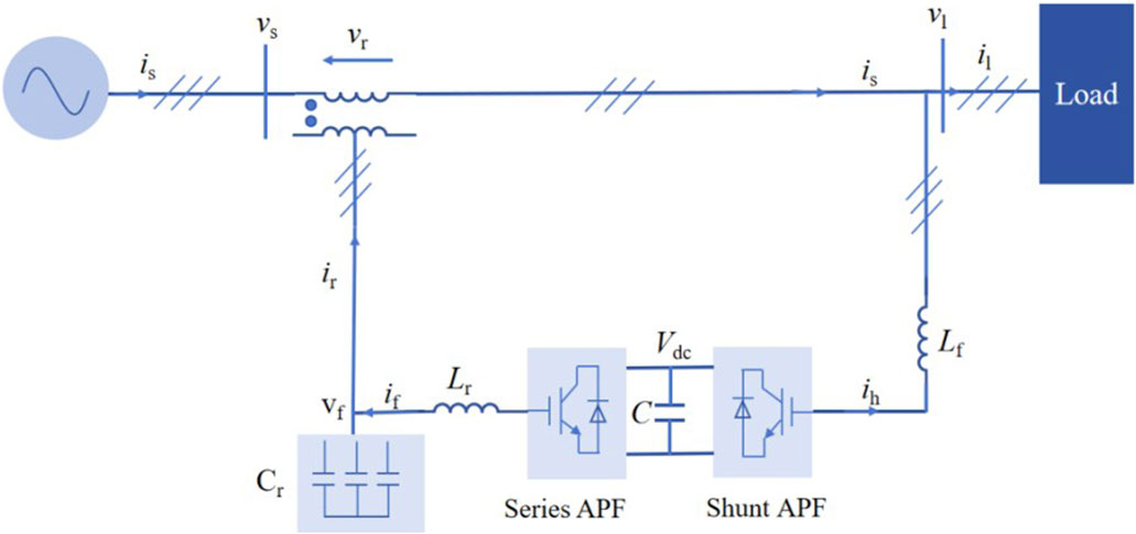
Figure 1. Unified power quality conditioner (UPQC) topological structure diagram of a three-phase, three-wire power system.
2.2 MSTOGI-PLL design
The UPQC control system compensates for voltage and current simultaneously, controlling the grid voltage as a stable fundamental positive-sequence component and the load current as a fundamental positive-sequence active component. When the grid is distorted, unbalanced, or has load side with unbalanced or nonlinear loads, the grid voltage, load voltage, and power flow will produce negative-sequence or harmonic components, and the generation of these components will bring errors to the compensation phase-locking detection link, which will affect the compensation accuracy and control effect of the UPQC. In a traditional UPQC control system, the SRF-PLL device is used, and the specific structure is shown in Figure 2.
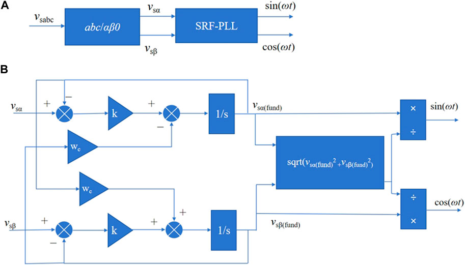
Figure 2. Synchronous reference frame phase-locked loop (SRF-PLL) specific structure diagram. (A) SRF-PLL input/output diagram. (B) Internal structure of SRF-PLL.
Figure 2A shows that the grid-side voltage vsabc is input into the coordinate converter to output the quantity vsα, vsβ, and vsα, and vsβ is input into the SRF-PLL device to output the phase angle sin(ωt) and cos(ωt), which are in the same phase with the input voltage of the grid side. The specific coordinate conversion formula is shown in Eq. 1:
Figure 2B shows the internal structure of the SRF-PLL. wc in Figure 2B is the cutoff frequency, where the magnitude of the cutoff frequency will be directly related to the filtering effect of the DC component in the network side; a smaller cutoff frequency can effectively extract the DC component, but a too small cutoff frequency will cause a delay in the detection process. Figure 2B shows that to obtain the synchronization phase angles sin(ωt) and cos(ωt), as shown in Eqs 2, 3 below, where vsα(fund) and vsβ(fund) in Eq. 2 are the values of the fundamental waveform positive-sequence components of the output in the αβ coordinate system.
The SRF-PLL can quickly and accurately lock the phase and frequency of the grid-side voltage under an ideal voltage, but the phase-locking accuracy of the SRF-PLL will be inaccurate under grid voltage distortion and harmonic imbalance, which affects the compensation performance of the UPQC. In order to provide the filter good output characteristics in both low- and high-frequency bands and to lock the phase accurately under the presence of grid distortion and harmonic imbalance, this paper adopts a new phase-locking device based on a second- and third-order generalized integrator, MSTOGI-PLL, which is capable of separating the DC and negative-sequence components efficiently.
When the power system experiences unbalanced disturbance, the symmetric component method is often used to decompose the voltage and power flow into positive-sequence, negative-sequence, and zero-sequence quantities. The Clark transform makes the zero-order component zero, and the detection of the fundamental waveform component is accomplished by separating the positive-order component. The symmetric component method used in the detection process is shown in Eq. 4. In Eq. 4, vsa+, vsb+, and vsc+ are the positive-sequence component values of the three-phase voltage on the grid side; vsa, vsb, and vsc are the three-phase voltage values on the grid side; and a is the phase operator.
The Park transformation is performed to transform the positive-sequence three-phase components into the αβ coordinate system, as shown in Eq. 5, where vsα+ and vsβ+ are the positive-sequence components of the grid-side voltage in the αβ coordinate system.
Bringing Eq. 4 into Eq. 5 and performing the Clark inverse transformation yield Eq. 6, where b in Eq. 6 is the time-domain phase-shift operator.
Equation 6 is the formula involved in the fundamental positive-sequence calculator (FPSC) module, where the time-domain phase-shifting operator b serves to make the positive-sequence signal of the grid-side voltage into two mutually orthogonal quantities. The specific structure of the MSTOGI is shown in Figure 3A, where the part inside the dashed line box is the module for eliminating the DC component, which is eliminated by subtracting the generated v3, and vm and bvm are two mutually orthogonal voltage outputs. ω0 is the resonant frequency of the MSTOGI, and the frequency of the input signal v is ωs. When ω0 = ωs, there is no DC in v1, and the AC component is the same as the input signal v. v2 contains DC and AC components, where the phase of the AC component lags the input signal v by an angle of 90°, and the amplitude and frequency of the AC component are the same as the v1 quantity. v3 contains only DC components of the same magnitude as those in v2, and the elimination of DC components is specifically shown in Eq. 7.
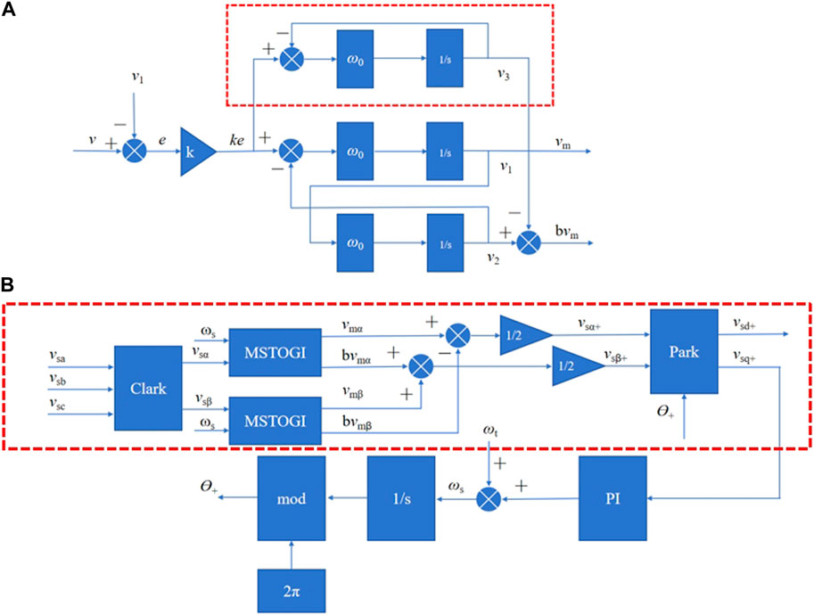
Figure 3. Mixed second- and third-order generalized integrator phase-locked loop (MSTOGI-PLL) specific structure diagram. (A) Specific structure diagram of MSTOGI. (B) MSTOGI-PLL specific structure diagram.
The flowchart of the adopted MSTOGI-PLL device is shown in Figure 3B, where ωt is a variable value, and the introduction of this value is mainly used to speed up the detection of the phase-locked loop; if this quantity is not introduced, the detection of the phase-locked loop can only be accelerated by adjusting the PI controller, but this process will produce a large overshooting amount, which increases the instability of the control system. In this study, this value ωt is set to 100π after empirical testing. Ɵ+ is the phase angle of the MSTOGI-PLL output. The red dotted box shows the specific structure of the MSTOGI-PLL.
Combined with Figure 3B, the values of the fundamental waveform positive-sequence components vsα+ and vsβ+ extracted for the network side are shown in Eq. 8.
2.3 Design of the UPQC system with ADRC or second-order STA control on the shunt APF side
2.3.1 UPQC system design with ADRC on the shunt APF side
In the DC voltage control link of the UPQC, the PI controller is often used (as shown in Figure 4A), which is simple in construction and has a fast and smooth control process. At the same time, the PI controller also has some shortcomings: in the initial moment of control, it can easily cause overshooting, and for closed-loop control, it can easily become sluggish, resulting in integral saturation and oscillations. icd under the PI controller will be positively fed back to the current compensation module, and finally, the shunt module needs to be given by the amount of current compensation ilα,h*, ilβ,h*. Inaccuracies in the control process will make the output current compensation inaccurate and, thus, affect the compensation effect of the UPQC; therefore, in this study, the PI controller of the orange module is replaced with the ADRC nonlinear controller to enhance the accuracy of the system control and then explore the compensation effect of the UPQC system based on the new MSTOGI-PLL + ADRC.
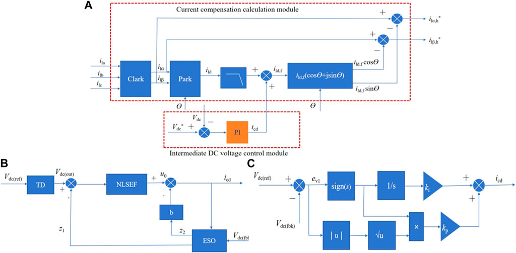
Figure 4. Shunt active power filter (APF)-side control block diagram. (A) Current compensation module. (B) Active Disturbance Rejection Controller schematic diagram. (C) STA controller specific structure.
The block diagram of the ADRC is shown in Figure 4B and consists of a tracking differentiator (TD), nonlinear state error feedback (NLSEF), and extended state observer (ESO). The variable Vdc(ref) given in Figure 4B is the reference value of the DC module capacitor voltage, Vdc(fbk) is the feedback value of the DC module capacitor voltage, and Vdc(out) is the tracking output value of the intermediate DC voltage.
The intermediate DC voltage module, if controlled by PI, is shown in Eqs 9, 10. ev1 is the difference between the reference voltage and the actual value at the intermediate DC terminal. icd is the output current of the intermediate DC module, and Kp(DC) and Ki(DC) are the proportionality coefficients and integral coefficients of the PI controller, respectively.
2.3.1.1 Design of the TD
The main function of the TD is to track and transition the reference value Vdc(ref) of the intermediate DC voltage, as shown in Eq. 11, where fal is the fal(.) function, and the specific expression of the fal function is shown in Eq. 12. In Eq. 12, e is the amount of error, a is the exponential value, δ is the base of the exponential function, and sign is the signal function. The fal function is central to the ADRC controller, and its mathematical expression is based on the empirical knowledge of control engineering: mathematical fitting of a large error, small gain, small gain, and large error.
In Eq. 12, δ is the filtering factor of the fal function, and an increase in δ can make the filtering effect better, but it also increases the tracking delay. a is usually taken between 0 and 1, and the smaller a is, the faster the tracking is, but the filtering effect will become worse. Therefore, when the parameters are selected, the values of δ and a need to be considered together. When |e|>δ, the fal function acts as a nonlinear feedback, which can make the system quickly approximate the input signal. When |e|≤δ, the expression of the fal function behaves as a low-pass filter.
2.3.1.2 Design of the ESO
In the ADRC controller, the ESO is mainly used to make observations on the uncertainty and disturbance of the system, as shown in Eq. 13. In Eq. 13, u(t) is the control quantity, and in this study, u(t) is the ADRC output value icd.
In Eq. 13, β2 and β3 are two parameters in ADRC that need to be set empirically. In the case of relatively large values of β2 and β3, it is favorable to improve the ESO tracking speed. However, too large values will cause the system to oscillate and overshoot. Usually, β3 is 1∼2 orders of magnitude larger than β2.
2.3.1.3 Design of the NLSEF
The NLSEF mainly makes a difference for the reference signal output from the TD, the differential signal, and the state signal output from the ESO, and then, it combines these signals nonlinearly to obtain the error feedback control quantity. Specifically, it is shown in Eq. 14, where z1 is the observed value of Vdc.
The disturbance compensation process of the final control output icd is shown in Eq. 15
2.3.2 Design of the UPQC system with the second-order STA on the shunt APF side
Sliding mode control is a kind of discrete nonlinear control, and traditional sliding mode control is prone to a vibration jitter phenomenon. The super-twisting sliding mode control applies the discrete control law to a higher order in the operation process, realizing the continuity of the control quantity in time, and, therefore, can effectively inhibit the generation of jitter vibration. The second-order STA control is denoted as a, which usually consists of two parts: a1 is the continuous function on the sliding mode surface, and a2 is the integral of the sliding mode surface in time, as shown in Eqs 16–19.
Equations 16, 17, in which ki, kp>0, are all positive gain parameters. Sign(s) is the sign function, and ρ is the exponential term coefficient. Sliding mode controller jitter is caused by signal discontinuity, and the integral signal as a continuous signal will not have the problem of the emergence of discrete quantities. Eq. 18, as discontinuous high-frequency switching quantities, no longer has a direct impact on the control law a, but the form of the sign function is transformed into the form of a time integral in the STA control law, which results in a continuous control signal, eliminating the jitter phenomenon in the sliding mode control. In terms of the value of the formula, in order to realize the convergence of the system in finite time, ρ in Eq. 8 should satisfy 0 < ρ ≤ 0.5, and the value of ρ in this study is 0.5. The sliding mode variable s is shown in Eq. 20:
The final second-order STA control law is obtained as shown in Eq. 21. The specific form of the second-order STA controller is shown in Figure 4C.
3 Simulation analysis
In this study, a new MSTOGI-PLL device is used to replace the conventional SRF-PLL device, and based on the use of the new phase-locking device, the compensation characteristics of the UPQC are investigated when two different nonlinear controllers are used in the DC voltage control module. It is mainly divided into three groups for comparison.
Group I: The UPQC system of MSTOGI-PLL + ADRC is compared to that of SRF-PLL + ADRC, focusing on which phase-locking device system is used for better compensation speed and effectiveness in the case of a common ADRC controller.
Group II: The UPQC system of MSTOGI-PLL + STA is compared to that of SRF-PLL + STA, which mainly investigates which phase-locking device system is used for better compensation speed and effect in the case of a common use of second-order STA controllers.
Group III: Comparative analysis between MSTOGI + PI in the UPQC system, MSTOGI-PLL + ADRC in the UPQC system, and MSTOGI-PLL + STA in the UPQC system mainly aims to study which controller adapted to the MSTOGI-PLL device can make the compensation effect of the system better in the case of all using the MSTOGI-PLL device.
The MATLAB/Simulink module was used to compare and analyze the simulation of the research group, and the specific parameters used for the three-phase, three-wire UPQC system in the simulation are shown in Table 1.
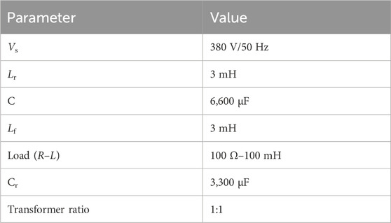
Table 1. Relevant parameters of the system in the simulation.
3.1 Group I: UPQC system of MSTOGI-PLL + ADRC vs. UPQC system of SRF-PLL + ADRC
The grid-side voltage is 380 V/50 Hz, and the simulation time is 2 s. At the beginning of the simulation, the grid-side voltage is 380 V, and after 0.5 s, the grid-side voltage becomes 1.2 times the initial value, and after 1 s, the grid-side voltage decreases to 0.8 times the initial value, and the grid-side voltage recovers after 1.5 s. In Figure 5, V-Source is the grid-side three-phase voltage vs, V-Load is the load-side three-phase voltage output vl, I-Source is the grid-side three-phase current value is, and I-Load is the load-side three-phase current output value il. Figures 5A, C show the waveforms of the grid-side and load-side voltage and current values of the UPQC system. Figures 5B, D show the partial magnification diagrams of the simulation for the periods 0.4–0.6 s with localized zoomed-in graphs. The ADRC controllers used in the first group all have the same coefficients, b = 500, β0 = 40, β1 = 1.6, β2 = 2, and β3 = 15.
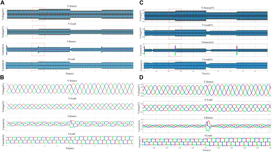
Figure 5. Voltage–current output plot of the same active disturbance rejection control (ADRC) controller using different filters. (A) Waveforms of network side and load side voltage and current values of UPQC system with MSTOGI-PLL+ADRC. (B) Localized amplified waveforms of grid-side and load-side voltage and current values of UPQC system with MSTOGI-PLL+ADRC. (C) Waveforms of grid-side and load-side voltage and current values of UPQC system with SRF-PLL+ADRC. (D) Localized amplified waveforms of grid-side and load-side voltage and current values of UPQC system with SRF-PLL+ADRC.
From the V-Source waveform graph, it can be seen that the variation in the measured voltage vs at the net side follows the simulation settings. In terms of voltage compensation, the UPQC system with MSTOGI-PLL + ADRC can compensate for the voltage quantities for the disturbances in time, resulting in a stable output vl at the load side. The UPQC system with SRF-PLL + ADRC produces significantly sharp peaks in the output vl at the peak and valley points in terms of voltage compensation.
In terms of current compensation, the UPQC system with MSTOGI-PLL + ADRC showed distortion in the is output value due to the nonlinear load accessed by the load, which no longer maintains a sinusoidal waveform and oscillates at 0.5 s and 1.5 s of the voltage change. However, il was effectively compensated, and its output waveform resembled a sine wave and did not produce oscillating values with is, indicating that the system was able to effectively compensate for the amount of power flow, making the UPQC system stable. In contrast, the UPQC system with SRF-PLL + ADRC produces a sharp burr oscillation at 0.5 s and 1.5 s after vs is subjected to grid-side interference with an amplitude of 15 A, and the output il waveform is more severely distorted than that of the UPQC system with MSTOGI-PLL + ADRC. It is shown that the UPQC system with MSTOGI-PLL + ADRC has better robustness when disturbances occur in the network-side system, the oscillation value of the network-side current is reduced by 50% when a sudden voltage change occurs, and the degree of voltage and current deformation of this system is minimized under the influence of nonlinear loads.
The Bode plots for the two filter inputs vsα and the positive-sequence component of the fundamental waveform vsα+ after filtering the output are shown in Figures 6A, B. Figure 6A shows that the MSTOGI-PLL filter is a band-pass filter, which has large amplitude attenuation in both the high- and low-frequency bands, and can effectively filter out the DC component and high harmonics in the input signal. Therefore, the UPQC system with this filter is more stable. Figure 6B shows the SRF-PLL acts as a band-pass filter with a narrower range of bands to be filtered, and the insensitivity of this filter to attenuation in the low- and high-frequency bands indicates that the filter does not filter well for the DC component and the higher harmonic components in the grid.
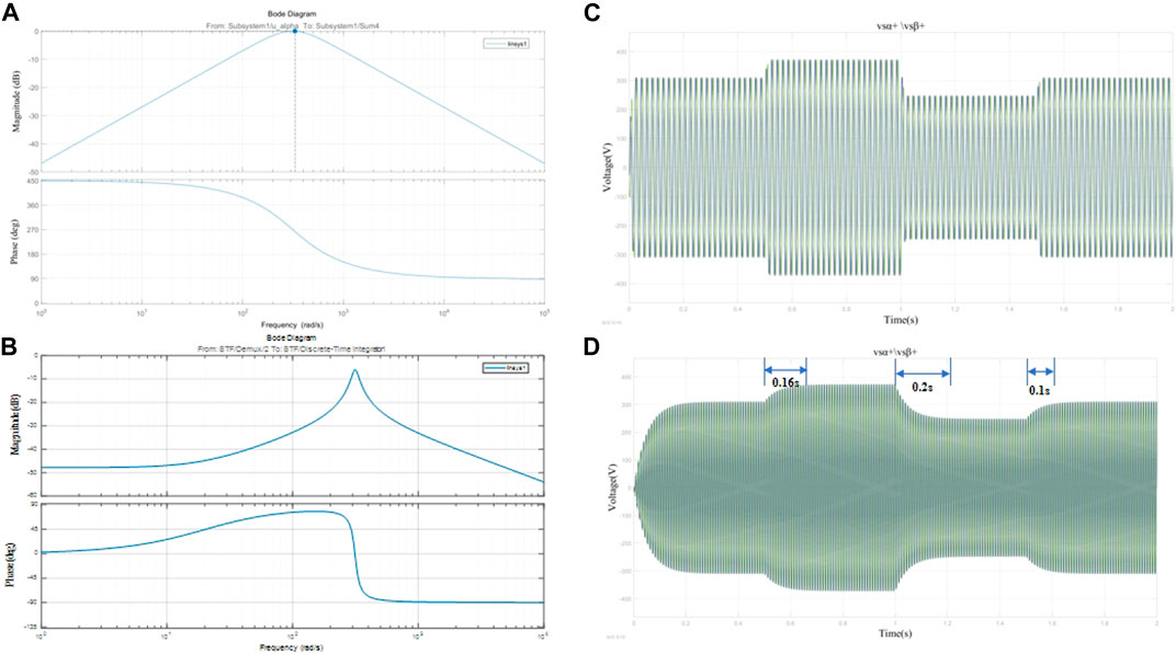
Figure 6. Bode plot and fundamental positive-sequence current component using different filtering devices. (A) MSTOGI-PLL Bode diagrams. (C) Positive-sequence vsβ+,vsβ+ volume response plots of the output of the UPQC system with MSTOGI-PLL+ADRC. (B) SRF-PLL Bode diagrams. (D) Positive-sequence vsβ+,vsβ+ volume response plots of the output of the UPQC system with SRF-PLL+ADRC.
Figures 6C, D show that, under the same premise of using an ADRC controller, the output vsα+ and vsβ+ of the UPQC system of MSTOGI-PLL + ADRC can follow the change in the grid-side voltage quantity vs in time under the effect of the MSTOGI-PLL filtering device. On the other hand, the positive-sequence component voltage values vsα+ and vsβ+ output from the SRF-PLL + ADRC UPQC system in the αβ coordinate system have a large overshoot. At the moment of voltage perturbation, the UPQC system with SRF-PLL takes 0.16 s, 0.2 s, and 0.1 s to respond in time, respectively. It indicates that the MSTOGI-PLL device has a faster response and better robustness performance of the UPQC system, provided that the same controller is used.
3.2 Group II: UPQC system of MSTOGI-PLL + STA vs. UPQC system of SRF-PLL + STA
In the second set of simulation experiments, the vs voltage perturbation is set as in the first set of experiments. Figures 7A, C show the waveforms of the network-side and load-side voltage and current values of the UPQC system with MSTOGI-PLL + STA and the UPQC system with SRF-PLL + STA. Figures 7B, D show the localized enlargement of the voltage and current values of the network side and load side of the two UPQC systems for simulation time 0.8–1.2 s. In the second set of experiments, the STA controller parameters were the same in both UPQC systems with a ki value of 9 and a kp value of 25.
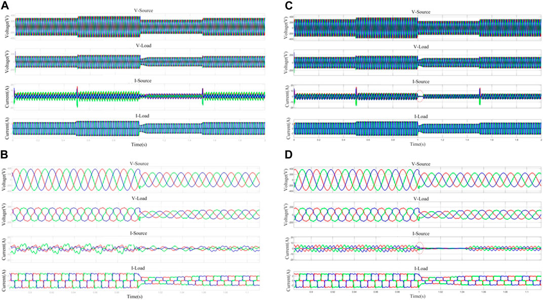
Figure 7. Voltage–current output plot of the same super-twisting algorithm (STA) controller using different filters. (A) Waveforms of network side and load side voltage and current values of UPQC system with MSTOGI-PLL+STA. (B) Localized enlarged view of grid-side and load-side voltage and current values of UPQC system with MSTOGI-PLL+STA. (C) Waveforms of network side and load side voltage and current values of UPQC system with SRF-PLL+STA. (D) Localized amplified waveforms of grid-side and load-side voltage and current values of UPQC system with SRF-PLL+STA.
The comparison of Figures 7A, C shows that when the STA controller is used and the phase-locking device adopts the MSTOGI-PLL or SRF-PLL, both the compensated voltage vl and the amount of current il at the output of the UPQC system are affected by the amount of perturbation. At 0.5 s and 1.5 s when the perturbation was added, the is electric flow of both UPQC systems showed large fluctuations in amplitude, which shows that the STA controller is not ideal in resisting the perturbation. When used with the SRF-PLL device, Figures 7C, D show is at 1 s when the value of the vs voltage decreases from 1.2 times to 0.8 times, followed by the phenomenon of a direct dropout in I-Source, a phenomenon that will bring harm to the power equipment in real life. Figures 7B, D show that both UPQC systems have effectively compensated for the voltage and current. The UPQC system with the SRF-PLL device produces large overshoots at the simulation moments 0, 0.5, 1, and 1.5 s and takes 0.2 s, 0.1 s, 0.2 s, and 0.1 s, respectively, to make the output value stable. It shows that the response speed and accuracy of the MSTOGI-PLL device are better than those of the SRF-PLL device.
When it comes to further separation of the positive-sequence components in the αβ coordinate system, Figures 8A, B show that the output of the base wave positive-sequence components vsα+ and vsβ+ of the UPQC system with MSTOG-PLL have achieved a fast response in the simulation moments of 0, 0.5, 1, and 1.5 s and the overshoot is small. The UPQC system with the SRF-PLL device produces larger overshoots at the simulation moments 0, 0.5, 1, and 1.5 s to the output. To stabilize fundamental waveform positive-sequence components vsα+ and vsβ+, more regulation time is needed, which indicates that the response speed and accuracy of the MSTOGI-PLL device are better than those of the SRF-PLL device, and it achieves the purpose of the design at the beginning.
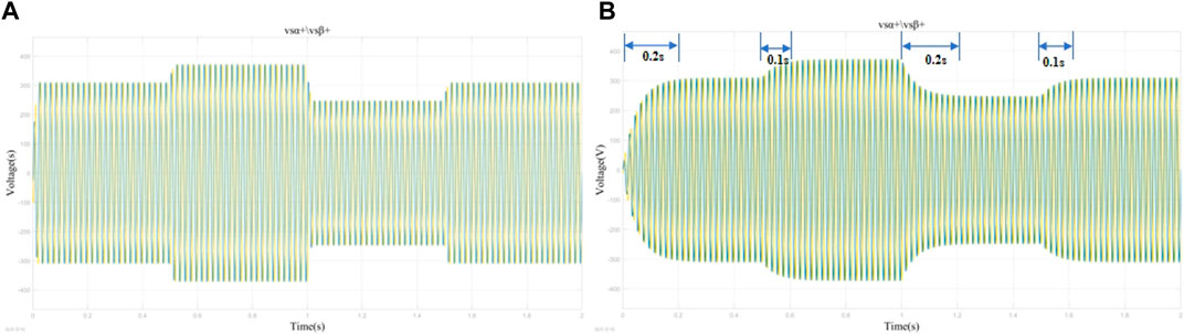
Figure 8. Output values of the fundamental positive-sequence components of the different filters using the STA controller. (A) Output positive order vsα+,vsβ+ volume response plots of UPQC system with MSTOGI-PLL+STA. (B) Output positive order vsα+,vsβ+ volume response plots of UPQC system with SRF-PLL+STA.
3.3 Group III: Comparative analysis among the MSTOGI-PLL + PI UPQC system, MSTOGI-PLL + ADRC UPQC system, and MSTOGI-PLL + STA UPQC system
In the third set of simulations, the simulation time is 2 s. Extreme disturbance is added in this set of simulations, i.e., a large number of 3rd, 5th, and 7th harmonics are added to the net side throughout the whole process. The net side voltage of the system increases to 1.2 times of the original voltage value at the simulation moment of 0.5 s, and the value of the system voltage recovers at the simulation moment of 1 s. At the simulation moment of 1.2 s, the grid-side voltage value vs decreases to 0 instantaneously and keeps the voltage 0 for 0.3 s, and the grid-side voltage value recovers at the simulation moment of 1.5 s. The compensation characteristics of the UPQC system using an MSTOGI-PLL device with different controllers are investigated in this extreme environment. Since the simulation environment was changed, some parameters of the controllers in this set of comparisons were readjusted, i.e., Kp = 0.2 and Ki = 0.3 in the PI controller, kp = 6 and ki = 30 in the STA controller, and b = 690, β0 = 30, β1 = 1.6, β2 = 4, and β3 = 40 in the ADRC controller.
Figures 9A, C, E show the waveforms of the grid-side and load-side voltages of the UPQC system, and Figures 9B, D, F show the localized magnification of the grid-side and load-side voltages at the simulation moment of 1.9–2 s. Figures 9A, C, E show that when the grid voltage dips, the UPQC system with PI as the controller makes vl gradually decrease to 0 in the whole period of 1.2–1.5 s. The whole process takes approximately 0.3 s, and the system voltage does not instantly decrease to 0, which indicates that the system has a certain degree of immunity to disturbances. vl of the UPQC system with the STA as the controller did not decrease to 0 throughout the time period of 1.2–1.5 s, indicating that the UPQC system with the STA as the controller has immunity to disturbances, but there is a delay in the control. In the UPQC system with ADRC as the controller, vl gradually decreases to 0 in the period of 1.2–1.5 s, and the whole process takes approximately 0.2 s. The system has the ability of anti-interference and has optimal performance in terms of response speed and accuracy. Figures 9B, D, F show that in the time period 1.9–2 s, the system shows significant voltage distortion on the vs side due to a large number of harmonic disturbances. On the compensation side, the output vl of both the UPQC systems with PI and STA as controllers showed more severe distortion than the UPQC system with ADRC as a controller. Its output vl has a jagged deformation and dips in the peaks and troughs, and the deformation reaches a level of distortion compared to the vs input. The UPQC system with ADRC as the controller also produces a deformation in the vl value due to a large number of high harmonics; the deformation is not to the extent of distortion, and the output waveform can still be approximated as a sinusoidal waveform.
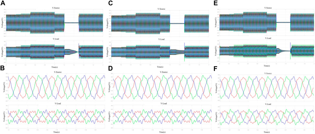
Figure 9. Network-side and load-side voltage outputs with different controllers of the same filtering device. (A) Network side and load side voltage waveforms of UPQC system with MSTOGI-PLL+PI. (B) Localized amplified waveforms of grid-side and load-side voltage of UPQC system with MSTOGI-PLL+PI. (C) Network side and load side voltage waveforms of UPQC system with MSTOGI-PLL+STA. (D) Localized amplified waveforms of grid-side and load-side voltages of UPQC system with MSTOGI-PLL+STA. (E) Network-side and load-side voltage waveforms of UPQC system with MSTOGI-PLL+ADRC. (F) Localized amplified waveforms of grid-side and load-side voltages of UPQC system with MSTOGI-PLL+ADRC.
Figures 10A, C, E show the UPQC system net-side and load-side current waveforms, and Figures 10B, D, F show the UPQC system net-side and load-side current localized amplified waveforms at 1.9–2.0 s. Figures 10B, D, F show that the output il waveforms of all three UPQC systems achieve an approximate sinusoidal waveform in terms of current compensation. Figures 10A, C, E show that when the voltage decreases in the period 1.2–1.5 s, the UPQC system with PI as the controller has a gradual decrease in current il during this period and takes nearly 0.3 s to decrease to 0. The UPQC system with the STA as the controller does not experience a decrease in the current il to 0 during this period, and there is a delay in the control. The UPQC system with ADRC as the controller takes 0.2 s for the il value to decrease to 0 during this period, and when the voltage value recovers at the moment of 1.5 s, the UPQC system with ADRC as the controller il generates the least oscillation. During the whole control process from 0 to 1.2 s, the UPQC system with ADRC as the controller produces the smallest ups and downs in il at the moments of 0.5 s and 1 s, indicating that the UPQC control system with MSTOGI-PLL + ADRC has the optimal immunity and response speed. The UPQC system with ADRC as the controller also produces minimum oscillations. This set of simulations shows that the UPQC control system with MSTOGI-PLL + ADRC has optimal stability and response speed.
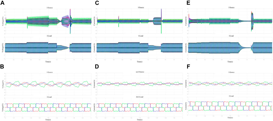
Figure 10. Network-side and load-side current outputs with different controllers of the same filtering device. (A) UPQC system network side and load side current waveforms for MSTOGI-PLL+PI. (B) Localized amplified waveforms of UPQC system grid-side and load-side current for MSTOGI-PLL+PI. (C) UPQC system network side and load side current waveforms for MSTOGI-PLL+STA. (D) Localized amplified waveforms of UPQC system grid-side and load-side currents for MSTOGI-PLL+STA. (E) UPQC system network side and load side current waveforms for MSTOGI-PLL+ADRC. (F) Localized amplified waveforms of grid-side and load-side currents of UPQC system with MSTOGI-PLL+ADRC.
4 Conclusion
In this study, a new MSTOGI-PLL device is designed for the UPQC phase-locking module, and by applying the second third-order generalized integrators, a module channel is constructed to eliminate the DC component, which realizes the effective separation of the DC and the negative-sequence components and, at the same time, realizes the effective compensation of the voltage and current under the influence of the voltage transient increase, transient decrease, and the nonlinear loads in the UPQC system. Compared with the traditional SRF-PLL device, the MSTOGI-PLL device can filter harmonics efficiently in the high- and low-frequency bands. The SRF-PLL device is insensitive to high- and low-frequency harmonics during the phase-locking process, and the locking takes longer, and the result of the output voltage positive-sequence component is more prone to overshooting than that of the MSTOGI-PLL, which will then affect the response speed of the UPQC.
In the controller selection, this study for the new MSTOGI-PLL device selected two nonlinear controllers, ADRC and second-order STA controllers, to study their suitability for the phase-locking device. The comparative analysis showed that both the nonlinear controllers in conjunction with MSTOGI are capable of compensating for the voltage and current quantities in the case of transient voltage increase, transient decrease, and nonlinear loads. However, when fighting against voltage transient increase and decrease disturbances, the ADRC controller is more resistant to disturbances, so that the UPQC system does not produce sudden changes in the output quantity, and at the same time, there is no control delay. In extreme environments, the UPQC system of MSTOGI-PLL + ADRC demonstrates better robustness with minimal voltage and current distortion. In extreme environments, such voltage and current distortions with harmonic components can interfere with the logic relationships of digital appliances in the circuit and reduce the rate of power supply. Thus, in extreme environments oriented to the simultaneous existence of multiple disturbances, the UPQC control system with fast response speed and lower degree of distortion can better achieve the compensation of the power system, improve the stability of the power system, and provide new ideas and references for the future power quality optimization problems of the power system.
Data availability statement
The original contributions presented in the study are included in the article/Supplementary Material; further inquiries can be directed to the corresponding authors.
Author contributions
YY: data curation, software, writing–original draft, and writing–review and editing. DL: writing–review and editing and investigation. YC: data curation, formal analysis, and writing–review and editing.
Funding
The author(s) declare that financial support was received for the research, authorship, and/or publication of this article. This research was funded by the Hunan Provincial Natural Science Foundation, Model predictive control system based on self-immunity improvement PMSM Weak Magnetic Control System for Urban Railway Trains under the System Applied Research (2023JJ50208).
Conflict of interest
The authors declare that the research was conducted in the absence of any commercial or financial relationships that could be construed as a potential conflict of interest.
Publisher’s note
All claims expressed in this article are solely those of the authors and do not necessarily represent those of their affiliated organizations, or those of the publisher, the editors, and the reviewers. Any product that may be evaluated in this article, or claim that may be made by its manufacturer, is not guaranteed or endorsed by the publisher.
References
Achlerkar, P. D., and Panigrahi, B. K. (2022). New perspectives on stability of decoupled double synchronous reference Frame PLL. IEEE Trans. Power Electron. 2022 (37-1), 285–302. doi:10.1109/TPEL.2021.3099162
Ai, S., Li, Z., and Nie, Z. (2023). Charge/discharge control strategy of flywheel energy storage system based on double hysteresis loop. J. Power Electron. Technol. 57 (5), 57–59.
Cheng, Q., Wang, Y., Cheng, Y., Wu, K., and Bai, Y. F. (2015). Modified double hysteresis current control method for unified power quality controller. Int. Trans. Electr. Energy Syst. 25, 713–730. doi:10.1002/etep.1868
Elik, D., and Ahmed, H. (2023). Enhanced control of superconducting magnetic energy storage integrated UPQC for power quality improvement in EV charging station. J. Energy Storage 2023. doi:10.1016/j.est.2023.106843
Fujita, H., and Akagi, H. (1996). Unified power quality conditioner: the integration of series active filters and shunt active filters. 27th Annu. IEEE Power Electron. Spec. Conf. Mil. 1996, 494–501. doi:10.1109/63.662847
Gao, J., He, H., and Ju, S. (2023). A dynamic voltage restorer control method for sampling model predictive control. Electr. J. 2023 (3), 25–29.
Genu, L. G. B., Limongi, L. R., Cavalcanti, M. C., Bradaschia, F., and Azevedo, G. (2020). Single-phase transformerless power conditioner based on a two-leg of a nine-switch converter. Int. J. Electr. Power & Energy Syst. 117, 105614. doi:10.1016/j.ijepes.2019.105614
Han, J., Li, X., and Sun, Y. (2022). Optimal design and decoupling control of series DC-link voltages for quadruple-active-bridge based UPQC. Int. J. Electr. power energy Syst. 2022, 140. doi:10.1016/j.ijepes.2022.108038
Han, J. Q. (1998). Auto disturbance rejection controller and it's applications. Control Decis. 13 (1), 19–23. doi:10.7210/jrsj.18.244
Ji, S., Jiang, H., and Liu, S. (2022). An LLC resonant converter digital hysteresis loop control strategy for battery charging. Low-voltage Electr. 2022 (005), 000.
Kumar, A., Patel, N., Gupta, N., and Gupta, V. (2022). Design, analysis and implementation of electronically interfaced photovoltaic system using ARM Cortex-M4 microcontroller. Comput. Electr. Eng. 98, 107701. doi:10.1016/j.compeleceng.2022.107701
Lakhdar, M., Adel, D., and Elkhalilyoucefa, B. (2023). Hybrid backstepping predictive direct power control of grid connected 3-phase 3-level PVG-UPQC based on optimised SVM technique for power quality improvement. L'Energia Elettr. 2023 (5), 100.
Lan, Z., Hao, R., and Jiao, H. (2022). Optimal foresight control of three-phase inverters based on repetitive control and state feedback. J. Electrotechnol. 37 (6), 9.
Li, L. (2022). UPQC shunt side based on sliding window iteration and hysteresis loop control algorithm. J. Comput. Syst. Appl. 2022 (11).
Li, P., Li, Y. W., and Yin, Z. H. (2015). Realization of UPQC H∞ coordinated control in microgrid. Int. J. Electr. Power Energy Syst. 65, 443–452. doi:10.1016/j.ijepes.2014.10.032
Li, S., He, W., Guo, Q., Lan, W., Wutong, H. E., and Qiang, G. (2022). Sliding mode control strategy for VIENNA rectifier under unbalanced grid voltage conditions. J. Power Supply 20 (3), 52–61. doi:10.13234/j.issn.2095-2805.2022.3.52
Li, S., Jiang, Z., Cui, Y., Kang, Y., Li, X., Li, H., et al. (2024). Enhanced dynamic state estimation of regional new energy power system under different abnormal scenarios. Int. J. Numer. Model.: Electron. Netw., Devic. and Fiel. 37 (2), e3216. doi:10.1002/jnm.3216
Lin, H. (2014). Improvement of power quality indicators and its outlook. Chin. J. Electr. Eng. 34 (29), 5073–5079.
Liu, F., and Wang, H. (2023). Application of fractional order PID control to an electric variable load loading system. J. Electr. Mach. Control 27 (8), 91–99.
Liu, L., Ning, W., and Zhang, H. (2019). Multi-objective optimization model and simulation validation of economic secondary frequency and voltage control for microgrids. J. Grid Technol. 43 (2), 9.
Liu, Q., Zeng, G., and Wang, J. (2022). Single-phase UPQC control strategy enabling two-fold power decoupling. J. Power Electron. Technol. 2022 (009), 056.
Lu, Y., Xiao, G., Wang, X., Blaabjerg, F., and Lu, D. (2015). Control strategy for single-phase transformerless three-leg unified power quality conditioner based on space vector modulation. IEEE Trans. Power Electron. 31 (4), 2840–2849. doi:10.1109/tpel.2015.2449781
Lv, Z., Liang, G., and Lu, Y. (2012). Study and simulation of improved id - iq harmonic detection methods. J. Power Electron. Technol. 46 (5), 81–83.
Meng, L., Ma, L., Zhu, W., Yan, H., Wang, T., Mao, W., et al. (2021). Control strategy of single-phase UPQC for suppressing the influences of low-frequency DC-link voltage ripple. IEEE Trans. Power Electron. 37 (2), 1–2124. doi:10.1109/tpel.2021.3106049
Miquelez-Madariaga, I., Schlipf, D., Elso, J., Guo, F., and Díaz de Corcuera, A. (2022). LIDAR based multivariable H∞ feedforward control for load reduction in wind turbines. J. Phys. Conf. Ser. 2022, 022070. doi:10.1088/1742-6596/2265/2/022070
Nasrollahi, R., Farahani, H., Asadi, M., and Amiri, P. (2022). A SOGI-PLL-based feedback-feedforward control system for three- phase dynamic voltage restorer in the distribution grid. Shahid Rajaee Teach. Train. Univ. 2022. doi:10.22061/JECEI.2021.7942.457
Nezhad, A. M., Tousi, B., and Sabahi, F. (2022). Power control of a grid-connected doubly fed induction generator using H∞ control and kalman filter. Int. Trans. Electr. Energy Syst. 2022, 1–19. doi:10.1155/2022/3771752
Niroomand, M., and Karshenas, H. R. (2017). Analysis and design of a series-parallel uninterruptible power supply with an improved control strategy for seamless transition. Electr. Power Components Syst. 45 (1), 22–33. doi:10.1080/15325008.2016.1233302
Pan, Z., Wang, X., Hoang, T. T. G., and T. L. F., (2023). An enhanced phase-locked loop for non-ideal grids combining linear active disturbance controller with moving average filter. Int. J. Electr. power energy Syst. 2023. doi:10.1016/j.ijepes.2023.109021
Patjoshi, R. K., and Mahapatra, K. (2016). Resistive optimization with enhanced PLL based nonlinear variable gain fuzzy hysteresis control strategy for unified power quality conditioner. Int. J. Electr. Power & Energy Syst. 83, 352–363. doi:10.1016/j.ijepes.2016.03.040
Patjoshi, R. K., and Mahapatra, K. (2017). High-performance unified power quality conditioner using non-linear sliding mode and new switching dynamics control strategy. IET Power Electron. 10 (8), 863–874. doi:10.1049/iet-pel.2014.0881
Patnaik, N., and Panda, A. K. (2016). Performance analysis of a 3 phase 4 wire UPQC system based on PAC based SRF controller with real time digital simulation. Int. J. Electr. Power Energy Syst. 74, 212–221. doi:10.1016/j.ijepes.2015.07.027
Phan, D. M., and Lee, H. H. (2018). A single-phase unified power quality conditioner with a frequency-adaptive repetitive controller. J. Electr. Eng. Technol. 13 (2), 790–799.
Setiawan, I., Facta, M., Andromeda, T., Hidayatno, A., Afrisal, H., et al. (2023). Implementation of sogi-pll algorithm for single phase grid connected inverters based on fixed-point arithmetic. Int. J. innovative Comput. Inf. control (4), 19.
Shi, R., Zhang, L., Wang, W., et al. (2022). Virtual inertia control based on improved cascaded SOGI-FLL. J. Sol. Energy 2022 (001), 043.
Su, X., Wang, X., Jiang, Z., and Cha, P. (2022). DDSRF-PLL-based complex vector conductance analysis of grid-connected inverters. J. Heilongjiang Univ. Sci. Technol. 32 (6), 771–778.
Tang, Q., Deng, C., Wang, Y., Guo, F. H., and Fan, S. (2024). Iterative observer-based resilient control for energy storage systems in microgrids under FDI attacks. IEEE Trans. [Smart Grid, early access]. doi:10.1109/TSG.2024.3382125
Wang, X., and Wang, K. (2022). LMI-based distributed robust H∞ control for DC microgrids. J. Sol. Energy 2022 (005), 043. doi:10.19912/j.0254-0096.tynxb.2020-0924
Wang, Z., Zhu, J., Zhao, X., Liu, Y., and Cao, H. (2023). Predictive duty cycle current hysteresis control for permanent magnet fault tolerant rim propulsion motors. J. Electrotechnol. 38 (3), 670–679.
Wei, H., Zhao, B., Lv, X., et al. (2023). Impact of SVG high and low voltage ride-through on low short circuit ratio grid and stabilization strategy. Invert. World J. 26 (10), 88–92.
Wei, X., Li, C., Qi, M., Luo, B., Deng, X., and Zhu, G. (2019). Research on harmonic current amplification effect of parallel APF compensating voltage source nonlinear load. Energies 12 (16), 3070. doi:10.3390/en12163070
Wu, H. (2022). Application of power system intelligence Technology in automation. China Sci. Technol. J. Database, Industry 2022 (8), 4.
Xu, Q., Ma, F., Luo, A., He, Z., and Xiao, H. (2016). Analysis and control of M3C-based UPQC for power quality improvement in medium/high-voltage power grid. IEEE Trans. Power Electron. 31 (12), 8182–8194. doi:10.1109/tpel.2016.2520586
Ye, J., Li, B., Chen, Y., and Zhu, S. (2022). A study on robust fuzzy control of chaotic oscillations in power systems based on matrix inequalities. J. Electrotechnol. 2022 (20), 1–3.
Zhang, H., Sun, C., Li, Z., Liu, J., Cao, H. y., and Zhang, X. (2017). Voltage vector error fault diagnosis for open-circuit faults of three-phase four-wire active power filters. IEEE Trans. Power Electron. 32 (3), 2215–2226. doi:10.1109/tpel.2016.2555583
Keywords: mixed second- and third-order generalized integrator, active disturbance rejection control, super-twisting algorithm, unified power quality conditioner, control accuracy, response speed
Citation: Yu Y, Li D and Chu Y (2024) Compensation characterization of the UPQC system under an improved nonlinear controller based on the MSTOGI-PLL device. Front. Energy Res. 12:1393629. doi: 10.3389/fenrg.2024.1393629
Received: 29 February 2024; Accepted: 16 April 2024;
Published: 09 May 2024.
Edited by:
Yu Huang, Nanjing University of Posts and Telecommunications, ChinaReviewed by:
Sahaj Saxena, Thapar Institute of Engineering and Technology, IndiaChao Deng, Nanjing University of Posts and Telecommunications, China
Xiaobing Liao, Wuhan University, China
Copyright © 2024 Yu, Li and Chu. This is an open-access article distributed under the terms of the Creative Commons Attribution License (CC BY). The use, distribution or reproduction in other forums is permitted, provided the original author(s) and the copyright owner(s) are credited and that the original publication in this journal is cited, in accordance with accepted academic practice. No use, distribution or reproduction is permitted which does not comply with these terms.
*Correspondence: Dan Li, lidan21@hnrpc.com; Yanting Chu, 2021858502@student.uitm.edu.my