A comparison of several maximum power point tracking algorithms for a photovoltaic power system
 Abdulellah Aifan G. Alsulami1
  Abdullah Ali Alhussainy1*
  Ahmed Allehyani2 Yusuf A. Alturki1,3
  Sultan M. Alghamdi1 Mohammed Alruwaili4
  Yahya Z. Alharthi5
- 1Department of Electrical and Computer Engineering, Faculty of Engineering, King Abdulaziz University, Jeddah, Saudi Arabia
- 2Electrical and Electronic Engineering Department, University of Jeddah, Jeddah, Saudi Arabia
- 3K. A. CARE Energy Research and Innovation Center, King Abdulaziz University, Jeddah, Saudi Arabia
- 4Department of Electrical Engineering, College of Engineering, Northern Border University, Arar, Saudi Arabia
- 5Department of Electrical Engineering, College of Engineering, University of Hafr Albatin, Hafr Al Batin, Saudi Arabia
This paper presents a comparative study between traditional and intelligent Maximum Power Point Tracking (MPPT) algorithms for Photovoltaic (PV) powered DC Shunt Motors. Given the nonlinearity of PV systems, they require nonstandard approaches to harness their full potential. Each PV module has a unique maximum power point on its IV curve due to its nonlinear characteristic nature. Power electronic converters are utilized to enable operation at that point. There are many different algorithms described in the introduction, each with its have their own advantages and drawbacks. Recognizing the potential enhancement of PV system efficiency through effective Maximum Power Point (MPP) tracking, this paper evaluates five MPPT methods under varying DC loads. The five algorithms will be as follows: Incremental Conductance and Perturb and Observe as traditional algorithms. Fuzzy Logic Control, Artificial Neural Networks, and Adaptive Neuro-Fuzzy Inference Systems as Intelligent Algorithms. While traditional algorithms generally produced acceptable results except for Perturb & Observe, intelligent algorithms performed well under rapidly changing solar radiation conditions. Due to inadequate data, intelligent algorithms relying on data training struggled to track the maximum power point when the temperature changed due to inadequate data used for the training. The analysis focuses on the time required by each method to reach peak power under different load conditions, solar irradiance, and temperature variations. The advantages and disadvantages of each MPPT with a shunt DC motor are detailed in the comparative study.
1 Introduction
Solar power has become a prominent leader in renewable energy due to its reduced cost and ecologically friendly nature, providing a sustainable alternative to fossil fuels (Hasaneen and Mohammed, 2008). The impact of solar energy on this endeavor has been remarkably substantial. The study mentioned in Yang et al. (2024) emphasizes the potential of rural rooftop photovoltaic (PV) systems in addressing regional energy disputes. Additionally, the study mentioned in ang et al. (2024) demonstrates how integrated solar electricity can contribute to sustainable urban growth. In addition, the utilization of solar energy in various systems has been examined in Gao et al. (2024), Yan et al. (2024) through the optimization of hybrid microgrids and renewable-based systems. In addition, the influence of solar energy on the control and dynamic economic dispatch in microgrids has been examined in references (Duan et al., 2023; Shirkhani et al., 2023). These contribute to the enhancement of our comprehension regarding the influence of solar energy on the formation of future energy environments.
With the increasing popularity of PV systems, their production costs have decreased, although inefficiency continues to be a persistent issue. Both the temperatures of the cells and the intensity of sunlight have a crucial influence in determining the power output of photovoltaic (PV) systems. Due to the reliance of PV energy output on factors such as sun’s irradiance, ambient temperature, and load, there is no assurance of consistent energy delivery. MPPT, or Maximum Power Point Tracking, is the method used to identify the optimal operating point for a solar PV cell based on certain environmental conditions. By utilizing the Maximum Power Point Tracking (MPPT) technology, the photovoltaic (PV) module achieves enhanced performance and increased longevity. These tactics are employed to optimize the power output of a photovoltaic (PV) module by enhancing its operational efficiency. Figure 1 illustrates the relationship between output power and voltage, and demonstrates how it varies with different levels of solar irradiation. Figure 1 demonstrates that there is a specific point during operation where the PV module reaches its maximum usable power. At that instant, the system must be operated using a Maximum Power Point Tracking (MPPT) technique. Creating sustainable, efficient, and environmentally-friendly energy sources is a top priority in contemporary science and technology (Hasaneen and Mohammed, 2008). Solar power systems, due to their extensive availability, are leading the way in renewable energy research. Although the cost of photovoltaic systems has decreased, improving efficiency continues to be a difficult task. Both the ambient temperature and sunshine intensity have a considerable impact on the output power of these devices.
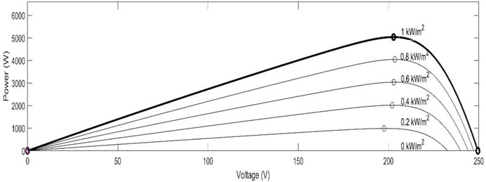
Figure 1. The effect of solar radiation variation on the output of PV arrays.
Unlike traditional power plants, solar energy production relies heavily on unpredictable factors like sunlight irradiance and temperature. This variability necessitates the use of Maximum Power Point Tracking (MPPT) techniques. MPPT ensures a solar photovoltaic (PV) cell operates at its optimal point for a given set of environmental conditions. This optimization extends the lifespan and improves the overall performance of the PV module. Figure 1 illustrates the relationship between output power, voltage, and varying solar irradiation levels. It clearly demonstrates a specific operating point where the PV module delivers maximum power. MPPT algorithms are crucial for operating the system at this optimal point.
Researchers worldwide are constantly striving to extract the most energy possible from renewable resources, particularly PV panels. Numerous MPPT algorithms have been proposed for both standalone and grid-connected PV systems (Bendib et al., 2015). Selecting the most suitable technique can be challenging as each offers advantages and drawbacks (Bhatnagar and Nema, 2013). Broadly, these methods can be categorized as traditional and intelligent approaches.
Traditional MPPT algorithms, such as Incremental Conductance (INC) and Perturb and Observe (P&O), are widely used due to their simple implementation and minimal sensor requirements (Teulings et al., 1993). The INC algorithm tracks the maximum power point (MPP) by monitoring the incremental and transient conductance of the PV system, efficiently delivering power to the load (Wasynezuk, 1983). Studies have shown that P&O and INC algorithms perform similarly under specific conditions (Sera et al., 2013).
However, with advancements in Artificial Intelligence (AI) and machine learning, researchers are exploring the potential of incorporating AI techniques into PV MPPT algorithms for improved accuracy, efficiency, and adaptability. AI-based MPPT solutions leverage the processing capabilities of AI algorithms to enhance MPP tracking and overcome limitations of conventional methods. AI facilitates modeling and understanding the non-linear characteristics of PV panels under various environmental conditions. Algorithms like Fuzzy Logic Control (Dehghani et al., 2021), Artificial Neural Networks (ANN) (Allahabadi et al., 2022), and Adaptive Neuro-Fuzzy Inference System (ANFIS) (Ibrahim et al., 2021) introduce a more dynamic and adaptable MPPT process. As shown in Figure 2, these AI methods offer an alternative approach to reaching the maximum power point by training on a dataset to achieve optimal controller behavior. While AI-based methods provide a promising alternative, they come with limitations such as complexity, cost, and difficulties in handling partially shaded irradiance scenarios.
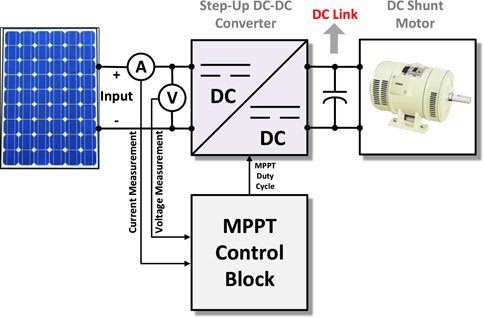
Figure 2. The traditional schematic diagram of operating DC shunt motors with solar PV.
The pursuit of developing more efficient and reliable Maximum Power Point Tracking (MPPT) algorithms is still ongoing. Bio-inspired algorithms inspired by natural phenomena hold significant promise. Further exploration of bio-inspired approaches, like improved versions of the Moth-Flame Optimizer for handling diverse shading conditions (Zhao et al., 2023), could be a fruitful avenue for future research. Additionally, metaheuristic optimization techniques offer exciting possibilities. Advancements in algorithms like the Novel Marine Predator Inspired Algorithm, focusing on global MPP convergence, warrant further investigation, particularly for complex shading scenarios (Qin et al., 2023). Finally, the potential of hybrid approaches that combine the strengths of traditional and intelligent techniques remains largely untapped. Building upon works like the Hybrid Firefly and Grey Wolf Optimization Algorithm, designed for rapidly changing irradiance, researchers can explore even more sophisticated hybrid models for a wider range of environmental challenges (Babu and Hussain, 2023). These areas of exploration hold the key to unlocking even greater efficiency and adaptability in future solar power systems. Table 1 summarize the key aspect in the literature.
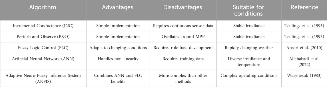
Table 1. Comparative tabular analysis of MPPT algorithms with references.
Despite advancements in MPPT algorithms, there remains a significant research gap concerning their performance when interfacing with specific loads, such as the DC shunt motor, which has not been extensively explored in existing literature. Traditional MPPT techniques like Incremental Conductance (INC) and Perturb and Observe (P&O) offer simplicity but may exhibit limitations when connected to dynamic loads like the DC shunt motor, which can introduce complexities due to its varying characteristics and operational dynamics. Conversely, AI-based approaches such as Artificial Neural Networks (ANN) and Adaptive Neuro-Fuzzy Inference Systems (ANFIS) are known for their adaptability but have not been thoroughly investigated in the context of such loads.
This study aims to address this gap by analyzing the performances of various MPPT algorithms (INC, P&O, ANN, ANFIS) specifically when connected to a DC shunt motor load. By focusing on this specific load type, the research aims to provide valuable insights into how different MPPT algorithms perform in real-world scenarios where dynamic loads play a crucial role in system behavior.
The significance of this research lies in its contribution to understanding how MPPT algorithms behave under the influence of a DC shunt motor load, a scenario that has not been extensively studied in the literature. By conducting a comprehensive analysis, this study seeks to identify the strengths and weaknesses of each algorithm in this particular context, thereby guiding the selection of appropriate MPPT techniques for PV systems interfacing with DC shunt motor loads.
The contributions of this research can be summarized as follows:
• Investigating the performance of various MPPT algorithms (INC, P&O, ANN, ANFIS) when connected to a dynamic DC shunt motor load.
• Providing valuable insights into how different MPPT algorithms behave under the influence of a specific load type, facilitating informed decision-making in the selection of MPPT techniques for PV systems.
• Bridging the gap in understanding the behavior of MPPT algorithms in real-world scenarios where dynamic loads like the DC shunt motor are prevalent, thereby contributing to the advancement of MPPT technology in practical applications.
These contributions hold significant implications for the design and optimization of PV systems, particularly in scenarios where dynamic loads play a critical role in system performance and efficiency. By shedding light on the performance of MPPT algorithms with a DC shunt motor load, this research aims to pave the way for further advancements in the field of PV system optimization and control.
The rest of this section will provide a detailed introduction to various Maximum PowerPoint Tracking algorithms, including Incremental Conductance, Perturb and Observe, Fuzzy Logic Control, Artificial Neural Networks, and Adaptive Neuro-Fuzzy Inference System. Section 2 delves into the configuration of the Photovoltaic System, covering modeling, parameters used in this research (Photovoltaic Array, Boost Converter, DC Shunt Motor), and the methodology employed. Section 3 presents the obtained results, analyzes the performance of the system under various weather conditions with each algorithm, and discusses the key takeaways from our research.
1.1 Incremental conductance method
Many traditional MPPT techniques rely on the principle that the peak power point occurs when the P-V curve’s slope is zero (Ibrahim et al., 2021). The rate of change as a measure of “power sensitivity” to voltage adjustments.
• If the power increases with voltage (
• Conversely, if the power decreases with voltage (
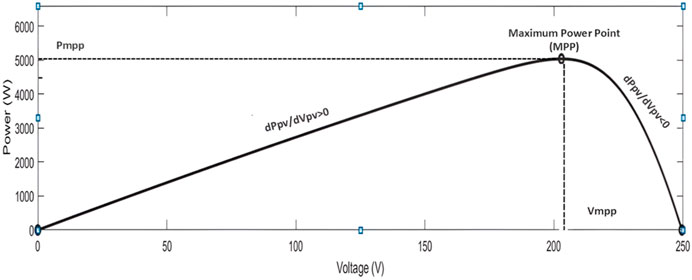
Figure 3. The maximum power point of the PV power.
Based on this principle, algorithms like Incremental Conductance (IC) continuously calculate (dP/dV), which represents the “instantaneous conductance” of the system. It then compares this value to the actual “incremental conductance” calculated from voltage and current changes. Figure 4 visualizes the process of adjusting voltage based on this comparison to continuously track the MPP (Elbaset et al., 2020).
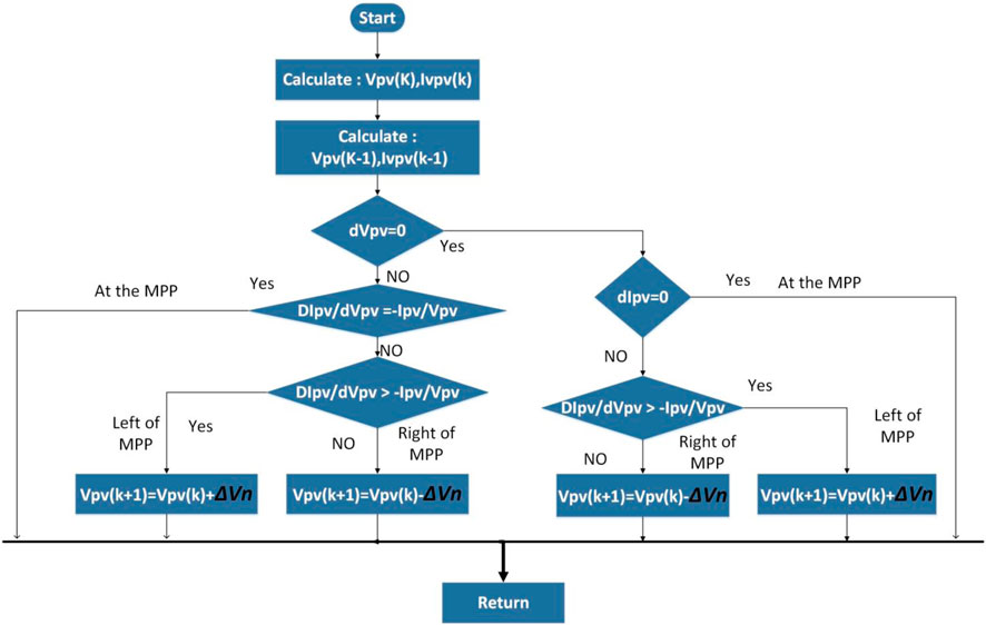
Figure 4. The flowchart of the incremental conductance method.
1.1.1 Perturb and observe
The system manipulates both current and voltage by adjusting a converter’s operating cycle (Ebrahimi, 2017). When power falls below peak efficiency, voltage is boosted. Conversely, if power exceeds its optimum level, voltage is reduced. This “Perturb and Observe” (P&O) approach is favored for its simplicity but suffers from power fluctuations around the peak point. See Figure 5 for a visual representation of the algorithm (Hart, 2011).
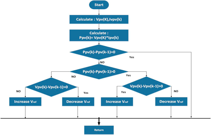
Figure 5. The flowchart of the P&O method.
1.2 Fuzzy logic control method
Fuzzy Logic Control (FLC) evaluates the data with varying variables as opposed to explicit logic, which evaluates the data using only true or false. In FLC, we have varying variables between true or false which allows for a more accurate evaluation of the data. The variables in fuzzy logic are converted into linguistic variables to describe the different degrees of the data (Eltamaly, 2020).
FLCs stand out in maximum power point tracking (MPPT) due to their ability to perform effectively without requiring prior knowledge of the photovoltaic (PV) system. This characteristic makes FLCs particularly well-suited for scenarios with rapidly changing weather conditions, where swift adaptation is crucial (Ansari et al., 2010; AzzouziM, 2012).
During MPPT with FLCs, the system’s power output undergoes continuous measurement and evaluation. To assess the trend towards the MPP, the rate of change in power with respect to voltage (dP/dV) is calculated. This information, along with the current error (E(k)) and its rate of change (ΔE(k)), forms the input to the FLC, guiding its decision-making process using Eqs 1, 2 as follows (Samosir et al., 2018):
Analyzing the error signal, E(k), and its change, ΔE(k), helps understand the location and movement of the MPP on the P-V curve. The error value shows whether the MPP is to the left or right of the present operating point, whereas the change in error reflects the MPP’s direction of travel. Using these indications, a control system may make smart modifications to approach the MPP and maximize power generation (Elbaset et al., 2020; Ibrahim et al., 2021).
Fuzzification converts the error E(k) and change of error ΔE(k) into fuzzy inputs using a membership function, such as Negative Big (NB) and Positive Big (PB). The inference engine will use the rule of assessing the input to determine the FLC’s suitable linguistic value output. The rules in the inference engine manage the boost converter’s duty cycle and monitor power changes. De-fuzzification converts the inference engine’s output from linguistic variables to mathematical variables with crisp values, as explained in (Wasynezuk, 1983). Figures 6–8 illustrate the membership functions of E(K), ΔE(k), and the output membership function. Table 2 shows the Fuzzy rules that were utilized in the inference engine stage that controlled the input and output variables.
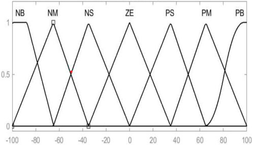
Figure 6. Membership function of E(K).
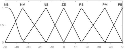
Figure 7. Membership function of ΔE(K).
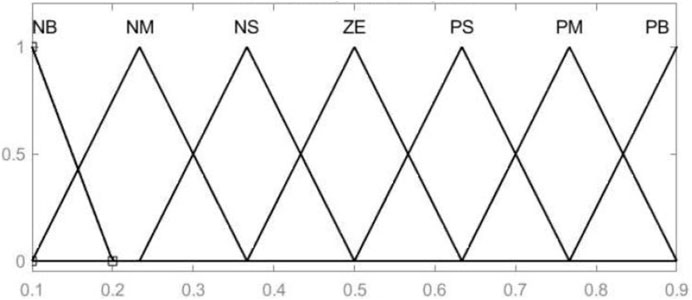
Figure 8. Membership function of D(K).
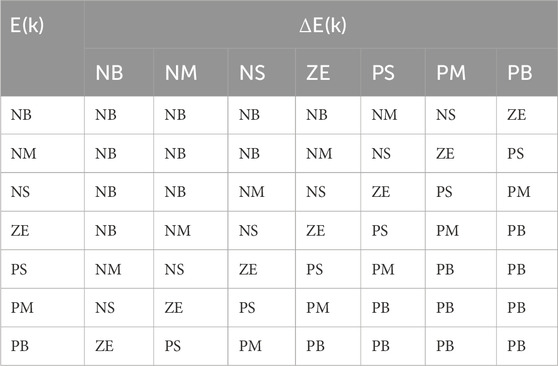
Table 2. The fuzzy rules used in the inference engine stage.
1.3 Artificial neural networks method
Artificial Neural Network (ANN) is an information processing technique inspired by biological neurons to simulate the neurons in human brains. ANN is a type of supervised learning algorithm, which means that it learns by examples. When the ANN is subjected to training sets, it adjusts the weights based on the learning rule (Ebrahimi, 2017). The architecture of a simple ANN is shown in Figure 9.
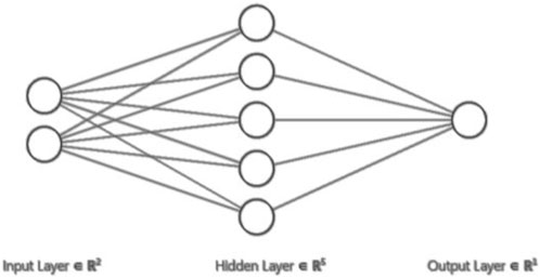
Figure 9. The architecture of a simple ANN.
The simple ANN here consists of an input layer, hidden layer, and output layer connected with the weights. Any layer may consist of many neurons or nodes, as we see here in the hidden layer, which contains five neurons. Multi-hidden layers can also be used in the ANN. Any nonlinear system can be modeled using ANN with suitable representation, making it useful for solving nonlinear systems. Moreover, ANN is very useful for handling incomplete or corrupted data because the ANN does not require any apriori knowledge (Ebrahimi, 2017).
ANN can be used for pattern recognition and classification as well as help in optimization problems, prediction, and control. In power systems we can use ANN in Load forecasting, economic dispatch, security assessment, fault location problems, and power system stability and control (Hart, 2011). As in Eltamaly (2020), the authors recommended using artificial neural networks (ANN) to track the highest power point under various meteorological circumstances. The ANN consists of three layers: the input layer, which includes the irradiance and temperature, the hidden layer, and the output layer, which estimates the voltage at the highest power point, as shown in Figure 10. The temperature range is 25°C–55°C, and the sun radiation range is 0–1,000 W/m2. The ANN was trained with the error back propagation approach. Figure 11 depicts the structure used to track the MPP, with the inputs being solar radiation (G) and temperature (T), and the controller estimating the voltage at maximum power (Vmpp). Then, the difference is attenuated based on the used system to be the required change in the duty cycle ±ΔD.
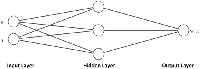
Figure 10. The structure of the ANN used in MPPT.
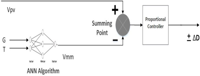
Figure 11. The Structure of used ANN in tracking the maximum power.
1.4 Adaptive neuro fuzzy inference system
Instead of relying solely on human-created rules, the ANFIS enhances performance by leveraging the capabilities of ANNs and FLC. ANFIS employs an ANN to analyze input data, minimize error [E(k)] and rate of change [ΔE(k)], and predict the desired output voltage at the highest power point. This predicted output is supplied to the FLC, which dynamically adjusts the duty cycle of the control parameters to keep the system running at peak efficiency. Using ANN in ANFIS serves two important purposes: first, it decreases error when compared to completely hand-tuned rules, and second, it automates the optimization process, removing the time-consuming trial-and-error approach to rule and membership function creation. Furthermore, FLC’s intrinsic tolerance for imperfect inputs improves the overall robustness and efficacy of ANFIS (Wasynezuk, 1983). Figure 12 shows the ANFIS architecture, which processes two input signals [E(k) and ΔE(k)] using seven separate membership functions. The resultant rule activations are then aggregated, and the output membership function calculates the system’s maximum power voltage.
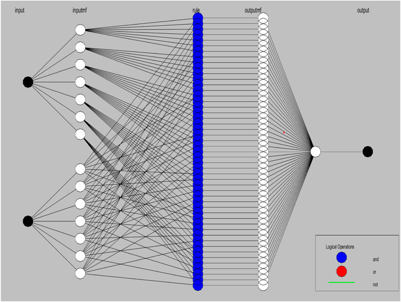
Figure 12. The structure of the used ANFIS.
The construction of the ANFIS utilized to track the greatest power point is depicted in Figure 13. The controller will estimate the voltage at maximum power (Vmpp) from the inputs of solar radiation (G) and temperature (T). Vmpp is then subtracted from the voltage of the PV array, and the difference is attenuated based on the used system to be the required change in the duty cycle ±ΔD as discussed previously.
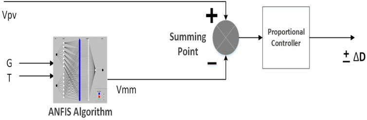
Figure 13. The structure of the used ANFIS.
2 Configuration of the photovoltaic system
The solar power generation unit, consisting of photovoltaic panels and a controller, will harness the sun’s energy and provide direct current electricity. This direct current will be electronically adjusted by a dedicated converter before powering the DC motor (detailed in Figure 14). Let’s delve deeper into the intricacies of this solar power generation unit.
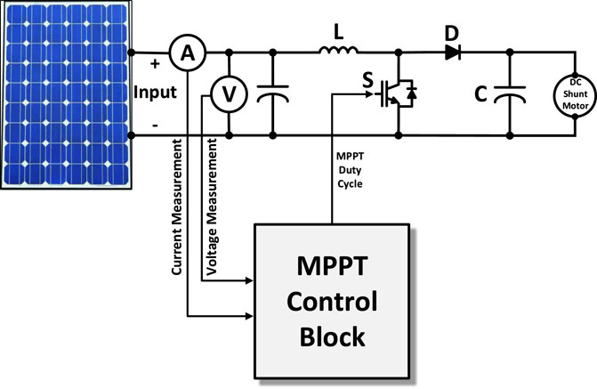
Figure 14. PV system, DC boost converter and DC shunt motor circuit schematic.
2.1 The Photovoltaic array
The PV system is comprised of semiconductor-based solar cells. Solar cells convert solar energy (or sunlight) into electrical energy (Ansari et al., 2010). The PV system’s current-voltage relationship is as follows using Eq. 3:
The equation illustrates how many critical elements influence the current output of a photovoltaic (PV) cell. Here’s a breakdown of every term:
K: Boltzmann constant, a fundamental physical constant related to temperature and energy is equal to 1.38 × 10⁻²³ (J/K).
q: The elementary charge of an electron is equal to 1.6 × 10⁻¹⁹ (C).
T: The temperature of the solar cell in kelvins (K).
VPV: The voltage measured across the output terminals of the solar cell (V).
A: A quality factor that accounts for non-idealities in the diode behavior, typically between 1.2 and 1.6 for crystalline silicon solar cells.
Rsh: The shunt resistance of the solar cell, a large resistance that allows some current to leak (Ω).
Rs: The series resistance of the solar cell, a small resistance that impedes the flow of current (Ω).
Simply expressed, the equation states that the solar cell’s output current (IPV) is controlled by the balance of the light-generated current (Iph) and the currents passing through the diode (ID) and shunt resistance (Ish). The diode current is determined by the cell’s temperature, voltage, and quality factor, whereas the shunt resistance current is often minimal.
2.2 The boost converter
The power output of photovoltaic (PV) panels varies with the amount of sunlight (irradiation). To remedy this, a DC-DC boost converter is used. This device functions as a voltage regulator, generating a constant output voltage regardless of irradiance. This consistent voltage thus permits the use of the maximum power point tracking (MPPT) approach. As previously stated, MPPT optimizes a PV panel’s operating point to extract the most power. The boost converter is crucial to this process because it changes both the output voltage and current using the MPPT algorithm. The design of the boost converter requires careful consideration of various elements. These parameters may be computed using existing formulas, as explained in Bendib et al. (2015).
where VPV (the input voltage), Vdc (the output voltage from the converter), ΔVPV (the change in PV voltage), ΔV0 (the ripple of the output voltage), IPV (the maximum current of the array A), Ia (the boost converter inductor), ΔILa (the boost inductor’s ripple current), PPV (the nominal power of the PV array (W), fs [the switching frequency (Hz)], Ca (the PV array link capacitance (F), C1 (the DC link capacitance), and D (the duty cycle of the boost converter that is managed by the MPPT controller).
2.3 DC shunt motor
Instead of directly converting electrical DC power into mechanical energy, this type of motor operates by interacting with magnetic fields. Its unique parallel configuration, featuring an armature winding directly connected to a field winding, enables it to function. The complex behavior of this motor can be mathematically modeled, as detailed in AzzouziM (2012).
Where, La represents the armature circuit inductance, Ia represents the armature circuit current, Va represents the armature circuit voltage, Ra represents the armature circuit winding resistance, Lf represents the field circuit inductance, Vf represents the field voltage, Rf represents the field circuit winding resistance, ω represents the angular speed, Kϕ represents the DC Shunt motor flux, and TL represents the motor torque.
The load torque (TL) would fluctuate in steps from 0 to 4 s. At t = 0 s, the motor works without load, with a maximum speed of 300 rad/sec and a starting current of 42 A. The field current starts at zero and remains constant. At t = 0.5 s, the motor is completely loaded, and the speed drops to around 130 rad/sec rather than 250 rad/sec. In addition, the armature current rises from zero to 7.2 amps. At 1.5 s, the motor is half loaded, and the speed increases to 134 rad/sec due to the decreased load, while the armature current reduces to 3.3 A. At = 2.5 s, the motor is loaded at a fourth of its rated load, and the speed increases to 138 rad/sec while the armature current decreases to 1.6 A. Table 3 lists all of the PV system’s parameters, including the PV array, DC-DC Boost Converter, and DC shunt motor.
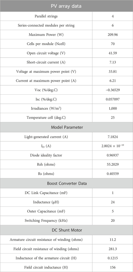
Table 3. The parameter of the PV system including the PV array, dc-dc Boost converter and DC shunt motor.
3 Results and discussion
In this section we will study the performance of the system when utilizing each algorithm under various weather conditions.
3.1 Case_1: solar radiation variation
A study investigated the performance of various algorithms for MPPT in a solar power system under changing solar radiation levels, Figure 15. The system maintained a constant temperature of 25°. The algorithms were evaluated under full, half, and quarter loads of the DC motor.
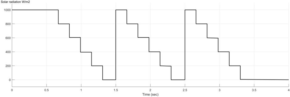
Figure 15. Solar radiation in case 2.
All algorithms performed well under the full rated load, successfully tracking the maximum power point. However, Figure 16 reveals significant drawbacks for P&O. P&O exhibited slower response times compared to other algorithms. Fuzzy Logic Control (FLC) introduced oscillations in the output power.
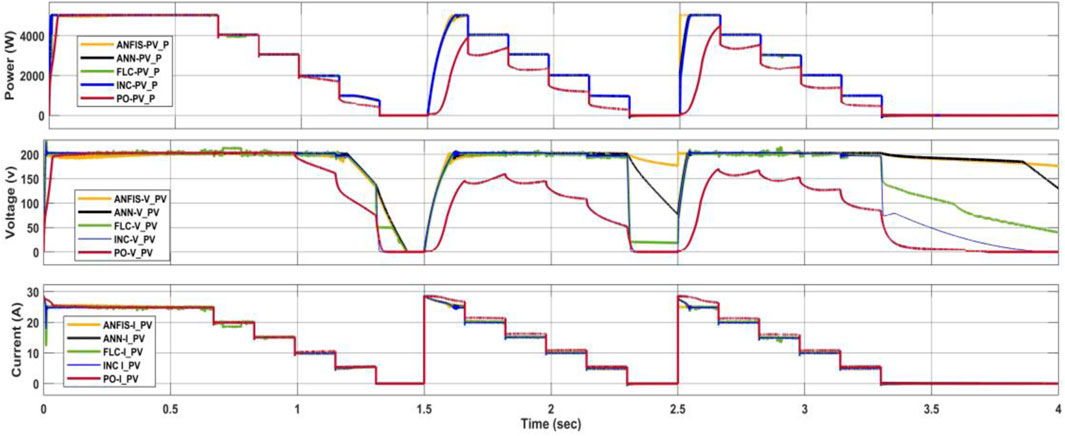
Figure 16. PV (P, V, and I) when varying the W/m2.
The limitations became more pronounced at lower loads. P&O entirely failed to track the maximum power point when the DC motor was loaded at half and a quarter of its capacity. In contrast, Incremental Conductance (IC), Artificial Neural Network (ANN), FLC, and Adaptive Neuro-Fuzzy Inference System (ANFIS) all successfully tracked the (MPP). Notably, ANFIS excelled at rapidly adapting to changing conditions. Under a quarter load with a sudden increase in radiation, ANFIS tracked the MPP within 2.4 s.
Furthermore, Figure 17 highlights the ability of ANN and ANFIS to maintain the desired voltage level during fluctuating radiation. P&O and IC, on the other hand, suffered from voltage drops to minimum levels. All the findings we get in this case study are like the findings of Chatterjee et al. (2008), Esmailian et al. (2014).
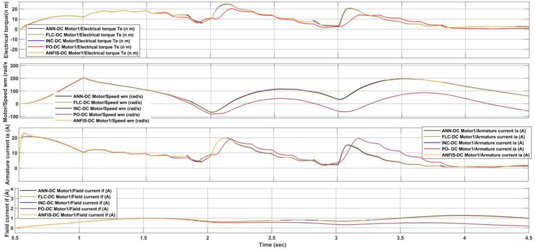
Figure 17. Torque, speed, armature current and field current of the DC motor when varying the solar radiation.
3.2 Case_2: temperature variation
A study investigated the performance of various algorithms for a system operating under steady solar radiation of 1,000 W/m2 (Figure 18). As the motor load decreased from full to a quarter of its rated capacity, the temperature rose from 25°C to 55°C. All algorithms successfully tracked the maximum power point at all load levels. However, P&O, IC, and FLC exhibited superior performance compared to ANN and ANFIS. This advantage is likely due to the limited temperature range (25°C–55°C) used to train the ANN and ANFIS models (Figure 18). Interestingly, P&O, IC, and FLC introduced current oscillations, whereas ANN and ANFIS resulted in smoother current patterns. Electrical torque peaked at roughly 19 N.m at full load and declined with reduced solar radiation for all algorithms. All the findings we get in this case study, like the findings of Fu et al. (2016), Gadalla et al. (2019) as shown in Figures 19, 20. The Results of the comparison will be shown in Table 4 below.
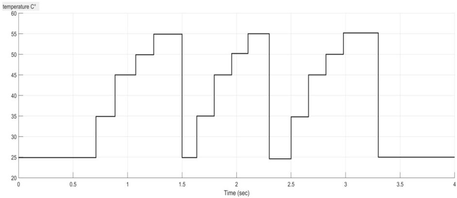
Figure 18. Temperature variation in case 3.
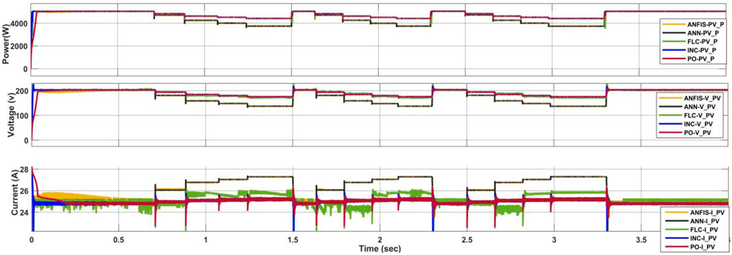
Figure 19. PV (P, V, and I) under the C0 variation case.
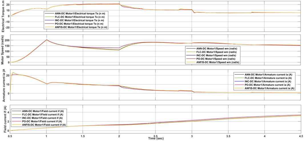
Figure 20. Torque, speed, armature current and field current of the DC motor in the temperture variation case.
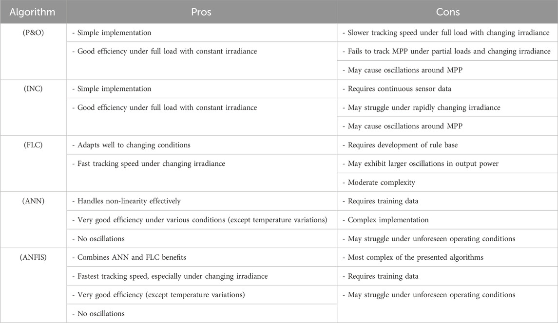
Table 4. Comparison of MPPT algorithms.
4 Conclusion
This paper investigated the performance of traditional (Incremental Conductance and Perturb & Observe) and intelligent algorithms (Fuzzy Logic Control, Artificial Neural Networks [ANN], and Adaptive Neuro-Fuzzy Inference System [ANFIS]) for maximum power point tracking (MPPT) under rapidly changing environments. Traditional algorithms performed well under varying solar radiation, but Perturb & Observe struggled at half and quarter loads. Intelligent algorithms excelled under rapid solar radiation changes, with ANFIS achieving the fastest tracking response. However, both ANN and ANFIS suffered limitations due to limited temperature data used for training, hindering their performance under temperature variations. Fuzzy Logic Control (FLC) demonstrated the most consistent and reliable performance across both changing solar radiation and temperature.
This study highlights the importance of considering training data comprehensiveness for intelligent MPPT algorithms. Additionally, the research focused on a DC motor load. Further investigation is required to assess the generalizability of these findings to other load types. The findings presented here hold promise for various applications requiring efficient solar power utilization, particularly those experiencing rapid environmental changes. These include photovoltaic systems integrated into buildings, electric vehicles, and autonomous mobile robots.
Future research should explore methods for incorporating real-time temperature data into the training process for intelligent MPPT algorithms. Additionally, investigating hybrid approaches that combine traditional and intelligent algorithms could leverage the strengths of each for broader applicability.
Data availability statement
The original contributions presented in the study are included in the article/supplementary material, further inquiries can be directed to the corresponding author.
Author contributions
AAG: Conceptualization, Data curation, Formal Analysis, Funding acquisition, Investigation, Methodology, Project administration, Resources, Software, Supervision, Validation, Visualization, Writing–original draft, Writing–review and editing. AAA: Conceptualization, Data curation, Formal Analysis, Funding acquisition, Investigation, Methodology, Project administration, Resources, Software, Supervision, Validation, Visualization, Writing–original draft, Writing–review and editing. AA: Conceptualization, Data curation, Formal Analysis, Funding acquisition, Investigation, Methodology, Project administration, Resources, Software, Supervision, Validation, Visualization, Writing–original draft, Writing–review and editing. YAA: Conceptualization, Data curation, Formal Analysis, Funding acquisition, Investigation, Methodology, Project administration, Resources, Software, Supervision, Validation, Visualization, Writing–original draft, Writing–review and editing. SA: Conceptualization, Data curation, Formal Analysis, Funding acquisition, Investigation, Methodology, Project administration, Resources, Software, Supervision, Validation, Visualization, Writing–original draft, Writing–review and editing. MA: Conceptualization, Data curation, Formal Analysis, Funding acquisition, Investigation, Methodology, Project administration, Resources, Software, Supervision, Validation, Visualization, Writing–original draft, Writing–review and editing.
Funding
The authors declare that no financial support was received for the research, authorship, and/or publication of this article.
Acknowledgments
The authors extend their appreciation to the Deanship of Scientific Research at Northern Border University, Arar, KSA, for funding this research through the project number “NBU-FFR-2024-2124-02.”
Conflict of interest
The authors declare that the research was conducted in the absence of any commercial or financial relationships that could be construed as a potential conflict of interest.
Publisher’s note
All claims expressed in this article are solely those of the authors and do not necessarily represent those of their affiliated organizations, or those of the publisher, the editors and the reviewers. Any product that may be evaluated in this article, or claim that may be made by its manufacturer, is not guaranteed or endorsed by the publisher.
Abbreviations
MPPT, Maximum Power Point Tracking; MMP, Maximum Power Point; PV, Photovoltaic; DC, Direct Current; INC, Incremental Conductance; PO, Perturb and Observe; STC, Standard Test Condition; FCL, Fuzzy Logic Control; ANN, Artificial Neural Networks; ANFIS, Adaptive neuro fuzzy inference system; P Control, Proportional Control; AI, Artificial Intelligence; NB, Negative Big; NM, Negative Medium; NS, Negative Small; PB, Positive Big; ZE, Zero; PM, Positive Medium; G, solar radiation; T, temperature; Vmpp, voltage at maximum power; TL, The load torque.
References
Allahabadi, S., Iman-Eini, H., and Farhangi, S. (2022). Fast artificial neural network based method for estimation of the global maximum power point in photovoltaic systems. IEEE Trans. Industrial Electron. 69 (6), 5879–5888. doi:10.1109/TIE.2021.3094463
ang, C., Kumar Nutakki, T. U., Alghassab, M. A., Alkhalaf, S., Alturise, F., Alharbi, F. S., et al. (2024). Optimized integration of solar energy and liquefied natural gas regasification for sustainable urban development: dynamic modeling, data-driven optimization, and case study. J. Clean. Prod. 447, 141405. doi:10.1016/j.jclepro.2024.141405
Ansari, M. F., Chatterji, S., and Iqbal, A. (2010). A fuzzy logic control scheme for a solar photovoltaic system for a maximum power point tracker. Int. J. Sustain Energ 29 (4), 245–255. doi:10.1080/14786461003802118
Anurag, A., Bal, S., Sourav, S., and Nanda, M. (2016). A review of maximum power-point tracking techniques for photovoltaic systems. Int. J. Sustain. Energy 35, 478–501. doi:10.1080/14786451.2014.918979
AzzouziM (2012). Comparaison between MPPTP&Oand MPPT fuzzy controls in optimizing the photovoltaic generator. Int. J. Adv. Comput. Sci. Appl. 3 (12), 57–62. doi:10.14569/IJACSA.2012.031208
Babu, T. S., and Hussain, M. A. (2023). A hybrid firefly and Grey Wolf optimization algorithm for maximum power point tracking of photovoltaic systems under rapidly changing irradiance. Sustain. Energy Technol. Assessments 58, 102724.
Bendib, B., Belmili, H., and Krim, F. (2015). A survey of the most used MPPT methods: conventional and advanced algorithms applied for photovoltaic systems. Renew. Sustain. Energy Rev. 45, 637–648. doi:10.1016/j.rser.2015.02.009
Bhatnagar, P., and Nema, R. K. (2013). Maximum power point tracking control techniques: state-of-the-art in photovoltaic applications. Renew. Sustain. Energy Rev. 23, 224–241. doi:10.1016/j.rser.2013.02.011
Chatterjee, D., et al. (2008). A review of solar MPPT techniques. Renew. Sustain. Energy Rev. 12 (4), 1194–1221. doi:10.1016/j.rser.2007.03.005
Dehghani, M., Taghipour, M., Gharehpetian, G. B., and Abedi, M. (2021). Optimized fuzzy controller for MPPT of grid-connected PV systems in rapidly changing atmospheric conditions. J. Mod. Power Syst. Clean Energy 9 (2), 376–383. doi:10.35833/MPCE.2019.000086
Duan, Y., Zhao, Y., and Hu, J. (2023). An initialization-free distributed algorithm for dynamic economic dispatch problems in microgrid: modeling, optimization and analysis. Sustain. Energy, Grids Netw. 34, 101004. doi:10.1016/j.segan.2023.101004
Ebrahimi, M. J. (2017). “30th power system conference (PSC2015),” in General Overview of Maximum Power Point Tracking Methods for Photovoltaic Power Generation Systems, Tehran, Iran, November, 2017, 228–233.
Elbaset, A. A., Abdelwahab, S. A. M., Ibrahim, H. A., and Eid, M. A. E. (2020) Performance analysis of photovoltaic systems with energy storage systems. Berlin, Germany: Springer Nature.
Eltamaly, A. M. (2020) Modern maximum power point tracking techniques for photovoltaic energy systems. Berlin, Germany: Springer International Publishing.
Esmailian, A., et al. (2014). A comprehensive review on recent advances in solar photovoltaic maximum power point tracking controllers. Renew. Sustain. Energy Rev. 30, 601–616.
Fu, X., Huang, S., Li, R., and Guo, Q. (2016). Thermal load prediction considering solar radiation and weather. Energy Procedia 103, 3–8. doi:10.1016/j.egypro.2016.11.240
Gadalla, M., Ghommem, M., Bourantas, G., and Miller, K. (2019). Modeling and thermal analysis of a moving spacecraft subject to solar radiation effect. Processes 7, 807. doi:10.3390/pr7110807
Gao, J., Zhang, Y., Li, X., Zhou, X., and J. Kilburn, Z. (2024). Thermodynamic and thermoeconomic analysis and optimization of a renewable-based hybrid system for power, hydrogen, and freshwater production. Energy 295, 131002. doi:10.1016/j.energy.2024.131002
Haque, M. T., and Kashtiban, A. M. (2006). Application of neural networks in power systems; A review. World Acad. Sci. Eng. Technol., 53–57.
Hart, D. W. (2011) Power electronics. New York, New York, United States: Tata McGraw-Hill Education.
Hasaneen, B. M., and Mohammed, A. A. E. (2008). “Design and simulation of DC/DC boost converter,” in Power System Conference, 2008. MEPCON 2008. 12th International Middle East, Aswan, Egypt, March, 2008, 335–340.
Ibrahim, S. A., Nasr, A., and Enany, M. A. (2021). Maximum power point tracking using ANFIS for a reconfigurable PV-based battery charger under non-uniform operating conditions. IEEE Access 9, 114457–114467. doi:10.1109/ACCESS.2021.3103039
Ong, C. M. (1998) Dynamic simulation of electric machinery. Upper Saddle River, New Jersy 07458: Prentice Hall PTR, 1–220.
Qin, Z., et al. (2023). A Novel marine predator inspired algorithm for maximum power point tracking of photovoltaic systems. IEEE Trans. Sustain. Energy 14 (2), 822–833.
Samosir, A. S., Gusmedi, H., Purwiyanti, S., and Komalasari, E. (2018). Modeling and simulation of fuzzy logic based maximum power point tracking (MPPT) for PV application. Int. J. Electr. Comput. Engineeing 8, 1315–1323. doi:10.11591/ijece.v8i3.pp1315-1323
Saxena, D., Singh, S. N., and Verma, K. S. S. (2010). Application of computational intelligence in emerging power systems. Int. J. Eng. Sci. Technol. 2 (3), 1–7. doi:10.4314/ijest.v2i3.59166
Sedaghati, F., Ali, N., Ali Badamchizadeh, M., Ghaemi, S., and Abedinpour Fallah, M. (2012). PV maximum power-point tracking by using artificial neural network. Math. Problems Eng. 2012, 1–10. Article ID 506709, 10 pages. doi:10.1155/2012/506709
Sera, D., Mathe, L., Kerekes, T., Spataru, S. V., and Teodorescu, R. (2013). On the perturb-and-observe and incremental conductance MPPT methods for PV systems. IEEE J. Photovoltaics 3 (3), 1070–1078. doi:10.1109/jphotov.2013.2261118
Shirkhani, M., Tavoosi, J., Danyali, S., Sarvenoee, A. K., Abdali, A., Mohammadzadeh, A., et al. (2023). A review on microgrid decentralized energy/voltage control structures and methods. Energy Rep. 10, 368–380. doi:10.1016/j.egyr.2023.06.022
Sumathi, S., Ashok Kumar, L., and Surekha, P. (2015) Solar PV and wind energy conversion systems. Cham: Springer.
Teulings, W. J. A., Marpinard, J. C., Capel, A., et al. (1993). “A new maximum power point tracking system,” in Proc. 24th Annual IEEE PESC, Seattle, WA, USA, June, 1993, 833–838.
Wasynezuk, O. (1983). Dynamic behavior of a class of photovoltaic power systems. IEEE Trans. Power Appar. Syst. (9), 3031–3037. doi:10.1109/tpas.1983.318109
Yan, C., Zou, Y., Wu, Z., and Maleki, A. (2024). Effect of various design configurations and operating conditions for optimization of a wind/solar/hydrogen/fuel cell hybrid microgrid system by a bio-inspired algorithm. Int. J. Hydrogen Energy 60, 378–391. doi:10.1016/j.ijhydene.2024.02.004
Yang, Y., Si, Z., Jia, L., Wang, P., Huang, L., Zhang, Y., et al. (2024). Whether rural rooftop photovoltaics can effectively fight the power consumption conflicts at the regional scale – a case study of Jiangsu Province. Energy Build. 306, 113921. doi:10.1016/j.enbuild.2024.113921
Youssef, A., El Telbany, M., and Zekry, A. (2018). Reconfigurable generic FPGA implementation of fuzzy logic controller for MPPT of PV systems. Renew. Sustain. Energy Rev. 82, 1313–1319. doi:10.1016/j.rser.2017.09.093
Keywords: photovoltaic (PV), maximum power point (MPP), incremental conductance (INC), perturb and observe (PO), standard test condition (STC), fuzzy logic control (FCL), artificial neural networks (ANN), adaptive neuro fuzzy inference system (ANFIS)
Citation: Aifan G. Alsulami A, Alhussainy AA, Allehyani A, Alturki YA, Alghamdi SM, Alruwaili M and Alharthi YZ (2024) A comparison of several maximum power point tracking algorithms for a photovoltaic power system. Front. Energy Res. 12:1413252. doi: 10.3389/fenrg.2024.1413252
Received: 06 April 2024; Accepted: 08 May 2024;
Published: 27 May 2024.
Edited by:
Flah Aymen, École Nationale d’Ingénieurs de Gabès, TunisiaReviewed by:
Rajeev Kumar, KIET Group of Institutions, IndiaImane Hammou Ou Ali, Mohammed V University, Morocco
Copyright © 2024 Aifan G. Alsulami, Alhussainy, Allehyani, Alturki, Alghamdi, Alruwaili and Alharthi. This is an open-access article distributed under the terms of the Creative Commons Attribution License (CC BY). The use, distribution or reproduction in other forums is permitted, provided the original author(s) and the copyright owner(s) are credited and that the original publication in this journal is cited, in accordance with accepted academic practice. No use, distribution or reproduction is permitted which does not comply with these terms.
*Correspondence: Abdullah Ali Alhussainy, aalhussainy0001@stu.kau.edu.sa