Dye Tracer Visualization of Infiltration Patterns in Soils on Relict Charcoal Hearths
 Anna Schneider
 Florian Hirsch
 Alexandra Raab
 Thomas Raab
- 1Chair of Geopedology and Landscape Development, BTU Cottbus-Senftenberg, Cottbus, Germany
- 2Chair of Environmental Economics, BTU Cottbus-Senftenberg, Cottbus, Germany
Anthropogenically modified soils are often characterized by a high heterogeneity of substrates and show unique patterns of water infiltration. Such effects are not limited to intensively used or disturbed agricultural and technogenic soils, but can also occur as legacies of former land use in forested areas. The remains of historic charcoal hearths represent a widespread legacy of historic land use. Soils at relict charcoal hearths (RCHs) are most prominently altered by the deposition of a layer of charcoal-rich substrate on top of the natural soil surface. The presence of such a technogenic layer can considerably influence infiltration and soil wetness patterns on the sites. This study describes the spatial patterns of infiltration and soil wetness at charcoal hearth sites compared with undisturbed sandy forest soils for a historic charcoal production area north of Cottbus, Germany. We characterized six plots on RCH and reference soils under pine, oak, and mixed forest by visualizing preferential flow patterns of infiltrating water in dye tracer experiments. Additionally, we characterized bulk density, soil organic matter (SOM) contents and water repellency, using water drop penetration time (wdpt) tests, of the RCH and reference soil horizons. The results reflect that the persistence of water repellency of both the technogenic substrates and the natural topsoils is extremely high under dry conditions, but is drastically reduced after wet antecedent conditions. The dye tracer experiments reflect increased preferential flow on the RCHs for dry soil conditions, for which infiltration is limited to very few flow paths in the technogenic substrate layer. Differences between RCH and reference soils are less clear for higher antecedent soil wetness, for which the results indicate more uniform wetting of the technogenic substrates. We conclude that the structural properties of the additional technogenic substrate layer of RCHs have characteristic effects on water infiltration, causing a high temporal variation of preferential flow in relation to antecedent soil moisture conditions. These effects can result in high heterogeneity of soil moisture for dry conditions, and generally in a high temporal variation of soil wetness in RCHs soils.
Introduction
Structural heterogeneity of soils can cause variable movement of substances through the soil profile. An important phenomenon related to soil structural heterogeneity is the preferential flow of water, i.e., a faster than average movement of water through parts of the soil porous matrix and a bypassing of other areas of the matrix (Beven and Germann, 1982; Gerke, 2006; Allaire et al., 2009). In sandy soils, preferential flow mainly occurs as unstable flow, and is often related to water repellency (Hendrickx et al., 1993; Ritsema and Dekker, 2000). Human land use often increases soil heterogeneity, disturbs established pore networks and therefore affects preferential flow mechanisms. Characteristic preferential flow processes in anthropogenically modified soils have been shown for mine spoil soils, where water flow is affected by internal technogenic layering structures, by the interfaces between the substrate matrix and larger intermixed fragments, and by spatially and temporally changing water repellency (Hangen et al., 2004; Gerke et al., 2009; Badorreck et al., 2010). Infiltration patterns are also modified in agricultural, tilled soils, where it has been shown that preferential flow is diminished as compared with untilled soils in the mixed, unstructured plow layer (Andreini and Steenhuis, 1990), and that, on the other hand, preferential flow can be initiated by horizon boundaries due to the tillage (Petersen et al., 2001). Among several other environmental implications, e.g., an increased leaching of chemicals (Flury et al., 1994; Petersen et al., 2001), preferential flow can also affect ecological site conditions through the availability of water for plants, as plant available water integrated over the soil profile is lower when only small parts of the profile are wetted during infiltration events.
Anthropogenic disturbances and modifications to soils do not only occur in recently and intensively used mining and agricultural areas, but also as legacy effects of historic land use, even in forested areas. The relicts of historic charcoal hearths (RCHs) are one example of such a forest use legacy. RCHs are widespread in many regions, as the production of charcoal in hearths, pits, or kilns has been an important component of forest use in many regions in central and northern Europe, e.g., in England (Bond, 2007), the Netherlands (Groenewoudt, 2007), central (Knapp et al., 2015) and northern Germany (Raab et al., 2015) since the Medieval Period. For later periods, extensive charring of wood in hearths is also reported from the northeastern USA (Gordon, 1996; Hart et al., 2008; Ko et al., 2011; Raab.T et al., 2017). Even today, charcoal produced in hearths represents a significant contribution to the energy supply in many rural areas and in developing countries (Chidumayo and Gumbo, 2013).
Several studies have characterized the effects of RCHs on plant colonization (Mikan and Abrams, 1995), growth (Buras et al., 2015; Criscuoli et al., 2017; Kerrè et al., 2017), and cover composition (Krause and Möseler, 1993; Carrari et al., 2016). Several recent studies also deliberately address the architecture and properties of the soils on such sites (Borchard et al., 2014; Criscuoli et al., 2014; Hardy et al., 2016; Hirsch et al., 2017; Mastrolonardo et al., 2018), mainly with a focus on soil chemistry. The physical and soil hydraulic characteristics of RCH soils have received relatively little attention so far. Several characteristic features of RHC soils potentially affect the infiltration and distribution of water in the soil profile.
The stratigraphy of RCHs is most prominently characterized by the presence of a technogenic layer on top of the natural soil profile that remained at the site after charcoal harvesting. This layer can be made up of a single layer or multiple sublayers, often alternating with layers of relocated mineral soil material, depending on how often and over which time periods the site was used for charring (Stolz et al., 2012; Raab.T et al., 2017). The substrate in this layer is usually a heterogeneous mix of charcoal fragments, organic and mineral soil material relocated during charcoal harvesting, and mineral matter that originated in the soil material used to seal the hearth. Thus, the bulk density, pore volume and pore size distribution of this substrate can vary considerably. The topsoil of natural soil profiles buried below the technogenic layers within RCHs may be truncated, depending on how the hearth site morphology and soils were prepared before the stacking of the wood, and can be mechanically compacted from the work involved in site preparation or from the weight of the hearth, both potentially resulting in disturbances of the soil porous system. Substrate hydrophobicity and water repellency might be increased within the charcoal-rich RCH layer and in the soil below the RCHs by the presence of hydrophobic charcoal fragments, by heat during the charring process (Doerr et al., 2000) and by modified input of hydrophobic organic compounds after burial of the soils. However, little is known about the relevance of such effects for soil conditions in RCHs. Thermally induced effects on soil water repellency and the hydrophobicity of charcoal decrease with time (Doerr et al., 2000; Inbar et al., 2014; Pusceddo et al., 2017). While clearly increased hydrophobicity has been found in soils enriched with freshly produced biochar (Kinney et al., 2012), Criscuoli et al. (2014) found decreased hydrophobicity in RCH soils, associated with lower bulk densities.
The hypothesis of this study was that preferential flow on RCHs is increased, as compared with undisturbed forest soils, because of high porosity and hydrophobicity of the charcoal-rich technogenic layer. The aim of our study was to characterize the spatial patterns of infiltration on historic charcoal hearth sites compared with undisturbed sandy forest soils by describing the preferential pathways of water flow. Therefore, infiltration experiments with a dye tracer solution were conducted, and soil profiles were described and analyzed for soils on and around three historic RCH sites in Brandenburg, Germany.
Materials and Methods
Study Sites
The study sites are situated in the forefield of the open-cast lignite mine Jänschwalde and the forest area Tauersche Forst, north of Cottbus, Germany (Figure 1). The area is characterized by mainly flat topography with elevations of about 80 m a.s.l. and was shaped by glacial and periglacial processes during the Saalian and Weichselian glaciations. The sandy, quartz-rich substrate is glaciofluvial in origin, but in some areas the presence of thin stone layers containing ventifacts reflects the subsequent formation of coversands by periglacial processes (Kasse et al., 2007). The dominant soils developed on these nutrient-poor substrates are Brunic Arenosols (Protospodic), according to the soil map (Bodenübersichtskarte) CC4750 Cottbus (BGR, 2015). The climate in the area is continental, with a mean annual temperature of 8.9°C and a mean annual precipitation of 549 mm, based on data from the Peitz climate station (Potsdam-Institut für Klimafolgenforschung., 2009). A high density of RCHs has been documented in this area by archeological excavations in the mine forefield (Rösler, 2008; Rösler et al., 2012) and by mapping based on digital elevation models derived from airborne LIDAR data (Raab et al., 2015; Raab.A et al., 2017). RCHs are usually characterized by circular platforms elevated about 20–40 cm above the surrounding area and slightly deeper ditches around the platforms. Dendrochronological dating of charcoal fragments from RCHs in the area suggests that each site was usually used only once or during a time period of only a few years (Raab et al., 2015).
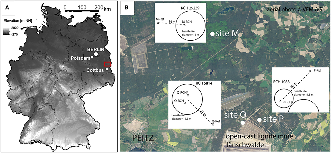
Figure 1. Location of the study area north of Cottbus, Germany (A) in the position of the study sites on an aerial photograph of the area around the forefield of the open-cast lignite mine Jänschwalde and the forest area around Tauer (B). Sketches of the sites (not to scale) show the position of the individual plots.
Three hearth sites and the surrounding areas were studied, and two plots were examined at each site (Figure 1).
Site P is located in the mine forefield and was covered by a pine (Pinus sylvestris L.) forest until the forest was cleared, which occurred shortly before the field work for this study in the course of mining preparation. Archaeological rescue excavations were conducted at this site in preparation for the mining and allowed for a detailed description of the RCH layouts. The remains of two adjacent charcoal hearths with diameters of 19 and 11.5 m were documented in the excavations. The ditch associated with the larger RCH intersects that of the smaller site, indicating that the two sites were constructed one after the other within a short period of time. Two plots were studied on this site: Plot P-Ref is located ~40 m from the RCHs in an area that shows no indications of surface modification by former land use. Plot P-RCH is located within the elevated platform of the smaller hearth site (RCH 1088, Figure 1).
Site Q is covered by oaks (Quercus rubra L.) and is located immediately outside of the mine forefield. However, the charcoal found on the RCH was derived from pine wood, indicating that the tree cover of the site was previously made up of conifers. The RCH mound studied on this site (RCH 5814, Figure 1) has a diameter of 18.5 m. The undisturbed forest soil for this site was studied in plot Q-Ref, which is located ~21 m from the center of the RCH. Plot Q-RCH is located close to the center of the hearth platform. Additionally, profile Q-RCH*, which is located a few meters away from profile Q-RCH on the hearth platform, was studied. However, dye tracer experiments for this plot could not be analyzed because of strong edge effects, so that only results of soil sample analyses are presented for this profile.
Site M is located about 8 km north of the mine forefield sites in the Tauersche Forst. It is covered by mixed forest, dominated by sessile oaks (Quercus petraea Liebl.) and pines (Pinus sylvestris L.). As for site Q, charcoal fragments in the RCH indicate the use of pine wood for charcoal production at the site. The diameter of the RCH mound (RCH 29239, Figure 1) is 18 m. Plot M-RCH is located on the hearth platform, and plot M-Ref is located in a distance of 10 m to the RCH.
Dye Tracer Experiments
To characterize the spatial patterns of infiltrating water, dye tracer experiments were conducted on plots with an area of 1.3 m2. This plot size was chosen to be able to analyze tracer distribution over a profile width of 1 m despite possible “edge effects” along the plots' boarders. The edges of each plot were defined with a metal partition that was pushed into the ground about 5 cm deep, until it was stable and no gaps between the frame and the soil were observed, to prohibit the lateral runoff of the applied dye tracer solution. We employed Brilliant Blue FCF as a tracer because it is highly visible, it is not toxic to the environment, and it displays low retardation in soils (Flury and Flühler, 1994, 1995). One kilogram of Brilliant Blue FCF was dissolved in 600 L of tap water. For each plot, 150 L of the tracer solution were applied. The necessary tracer concentration and amount of tracer solution to reach a good visibility of staining patterns had been determined beforehand in tests on smaller plots. The soil surface within the plots was covered with a plastic sheet at the beginning of the experiment and about 75 L of the tracer solution were applied to cover the complete area of each plot with 5–6 cm of Brilliant Blue FCF solution. The remaining 75 L were gradually poured on the plots after removal of the plastic sheet to maintain similar flood conditions during the infiltration process as long as possible. This procedure with infiltration under flood conditions with (as far as possible) constant pressure was chosen to exceed the infiltration capacity of the soil matrix and to reach high and relatively constant infiltration through the large pores of the soil, as recommended by Droogers et al. (1998) and Allaire et al. (2009).
For site P, infiltration experiments were conducted in October and November 2014 on the RCH and reference plot, respectively. Weather conditions during the infiltration experiments and sampling were similarly dry for both experiments, with only a few medium-intensity precipitation events during the preceding weeks. At site Q, the experiments were conducted in October 2015. Conditions were only slightly wetter than for site P, with some medium-intensity precipitation events before and slightly rainy conditions during the infiltration experiments. On site M, the infiltration experiments were carried out in April 2017. Several, but only low-intensity precipitation events had occurred in the weeks before, however, soil moisture was clearly higher than for the experiments conducted in autumn.
Beginning at the side of each plot, the soil profiles were excavated into several horizontal and vertical profiles. The excavation was performed several hours after the tracer solution was added to plot P-RCH, and 1 day after the experiments for all other plots. Three horizontal profiles were examined for each plot. When possible, these profiles were arranged so that they were separated from one another by 10 cm, but profile spacing had to be adapted in cases where profiles were disturbed by large roots. The depth and number of the vertical profiles were determined based on the soil stratigraphy revealed by the horizontal profiles.
To study the distribution of dye tracer in the profiles, we used orthorectified photographs and image analysis. For each profile, several close-up photographs of the profiles were taken and assembled into geometrically corrected image mosaics using AgiSoft PhotoScan software (Agisoft LLC, St. Petersburg, Russia). The measured distances between 9 and 12 raster points marked with tile markers were used as reference scales. The resolution of the images was reduced so that each pixel represents 1 mm2, and the images were delimited to the 1-m-wide area below the infiltration plot. In order to carry out separate analyses for different parts of the soil profiles, horizon and layer boundaries were marked in the photographs and images were split along these boundaries. To delineate the dyed areas, the images were processed using the free GNU Image Manipulating Program (GIMP, version 2.8; GIMP Development Team), Adobe Photoshop (Adobe Systems, San José, USA), and ImageJ (Rasband, 2012) using the following steps: (1) Images were corrected by a white balance, adjusted to the white tile markers. (2) The range of the hue of the color within the stained areas was determined and saturation was maximized within this color range and minimized for the remaining hues. For the pictures of site P, the range of hues within the stained areas coincided well with the green, blue and turquoise components (90–240°), while for pictures of sites Q and M, the range needed to be extended into the yellow hues (50–240°) to cover all stained parts of the profiles. (3) The image was decomposed into its Hue-Saturation-Value (HSV) components, and the saturation channel was extracted. (4) A threshold value was used to assign a pixel value of 255 (white) to the dye-covered areas, and a value of 0 (black) was assigned to other areas of the profile. (5) The areas of the tile markers, as well as stones and roots that were to be excluded from further analyses, were delimited manually, and pixel values of 125 (gray) were assigned to these areas. (6) The images were then analyzed using the R software package (R Core Team, 2017). Pixel values were redefined so that the dye-covered areas had a value of 1, non-covered areas had a value of 0, and areas excluded from the analysis were assigned NA values. Finally, the percentage of dye-covered pixels was computed for each row of the image, for the delineated horizons and for the whole image.
Soil Profile Description and Characterization
For each tracer experiment plot, a soil pit about 30 cm outside of the delimited plot area was excavated, described and sampled before the stained profiles below the plots were excavated. The soils were described according to the German Guidelines for Soil Mapping (Ad-hoc-AG Boden, 2005) and classified according to the World Reference Base for Soil Resources (IUSS Working Group WRB, 2014). From the vertical profiles below the tracer plots, undisturbed samples were taken at several depths using metal cylinders with volumes of 100 cm3 and heights of 4.05 cm. The sampling depths were adapted to the stratigraphy of each profile. For each depth, five replicate samples were taken at sites P and Q. For site M, the number of replicates was increased to 15 to better represent the high substrate heterogeneity.
To characterize the persistence of hydrophobicity of the substrates, water drop penetration time (wdpt) tests were conducted on the air-dry surfaces of the undisturbed samples. The wdpt test determines how long hydrophobicity persists on a sample surface and has often been used as a relatively easy method to characterize water repellency of sandy soils (Wessel, 1988; Doerr, 1998). Three droplets of water were applied to each sample, and the time required for the water droplets to completely infiltrate into the samples was measured. The penetration times were classified into five water repellency classes, following the classification scheme of Dekker and Jungerius (1990), which was developed for sandy substrates. Soil moisture at field conditions at the time of the infiltration experiments was determined after drying the samples at 105°C from bulk samples taken outside of the infiltration plots for sites Q and M, and from five (unstained) undisturbed samples taken within the plots for site P. The soil organic matter (SOM) content of bulk samples was assessed by loss-on-ignition (LOI) at 550°C. The bulk density of the undisturbed samples was determined after the samples were dried at 105°C for 24 h, following Hartge and Horn (2009).
Results
Soil Profile Description and Properties
Except for the technogenic deposits that were present at the RCHs, the studied soil profiles are similar in terms of their stratigraphy. The Weichselian glaciofluvial sediments at the bases of the profiles are covered by periglacial coversands containing two stone layers. The grain size distributions are dominated by medium sand throughout the profiles. The undisturbed forest soils are Brunic Arenosols (Protospodic) with incipient podzolic eluviation in the topmost few centimeters of the topsoil. The thickness of the organic horizons (L/Of/Oh) varied between 4 cm at the Pinus site and about 7 cm at sites Q and M, and the thickness of the organo-mineral topsoil (A horizons) varied between about 13 cm at the mixed forest and Quercus sites and 18 cm at the Pinus site. Fine charcoal fragments, most likely derived from mechanical or aeolian translocation of charcoal during hearth operation or harvesting, were found in the topsoils at all the sites. The subsoil horizons of all studied profiles are affected by weathering and brunification. Two distinct stone layers containing ventifacts were found in the profiles on sites P and M, separating 30–40 cm thick sediment layers. In the profiles at site M, only one, less distinct stone layer occurred in a depth of about 40 cm. In the lowest parts of the profiles, i.e., from depths of about 1 m for the RCH profiles and about 80 cm for the reference profiles, the sandy sediments were stratified and showed redoximorphic features that presumably developed when the ground water table was higher in the past.
In the RCH plots, relatively thin organic horizons, which have a maximum thickness of 5 cm, are developed above the technogenic deposit remaining from the charcoal hearths. The soils that occur within the RCHs are classified as Spolic Technosols overlying Brunic Arenosols. The remains of the hearth operation are dark gray, relatively loose sediment layers that are rich in charcoal fragments. These layers have a thickness of up to 30 cm in the central parts of the RCHs. The lower boundary of each charcoal-rich layer is quite distinct and even. The buried topsoil horizons have similar thickness, colors and grain size distributions as the topsoil horizons in the undisturbed soil profiles. In parts of the profiles, the upper 2–4 cm of these topsoils have a slightly more reddish color, most probably as a result of thermal alteration of iron (hydr-)oxides (Hirsch et al., 2018). The uppermost centimeters of the buried topsoils, similar to the topsoils of reference profiles, show signs of podzolic eluviation. Together with the similar thickness, this shows that topsoils were not removed in course of hearth site preparation. This is consistent with detailed observations on other RCH soils in the area (Hirsch et al., 2018) and with the suggestion made in the royal Prussian order regulating charcoal burning in the region (Friedrich, 1779) to directly construct the hearth on top of the undisturbed ground vegetation for sandy soils. A slight disturbance of the uppermost centimeters of the topsoils, however, cannot be excluded, and might be indicated by the sharp upper boundary of the buried topsoil on site P.
As it might be expected, high LOI was determined for the technogenic layers of the RCH profiles (Table 1, Supplementary Table 1a), where LOI reflects both pyrogenic and pedogenic SOM. In the buried soil horizons below the RCH, LOI values are lower as compared with the topsoils of the reference profiles for all sites. Comparing the sites with different vegetation cover, relatively low LOI was determined for all horizons of the Pinus site profiles, LOI values are relatively high for all horizons of the Quercus site profiles, and a strong decrease from high LOI values in topsoils to low values in the subsoils was observed at the mixed forest site.
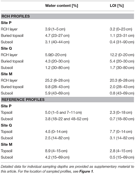
Table 1. Initial water contents at the time of the infiltration experiments and soil organic matter contents as assessed by loss on ignition (LOI) of the profile horizons (determined from bulk samples taken outside of the infiltration plots, except for water content data for profile P, determined as the mean of 5 undisturbed samples from unstained areas within the plot, sampling depths in parentheses).
A high spatial heterogeneity of bulk density is reflected by the variation between the undisturbed samples for all profiles, with highest variances observed in the topsoils of the reference soil profiles. The bulk density (Figure 2) of the technogenic RCH deposit is low, with values between 1.1 and 1.3 g cm−3. The bulk densities increase slightly with profile depth in most of the profiles. The bulk density of the organo-mineral topsoil is higher under the RCHs than for the reference profiles at sites P and Q, while bulk densities of the buried and reference topsoil are similar for site M.
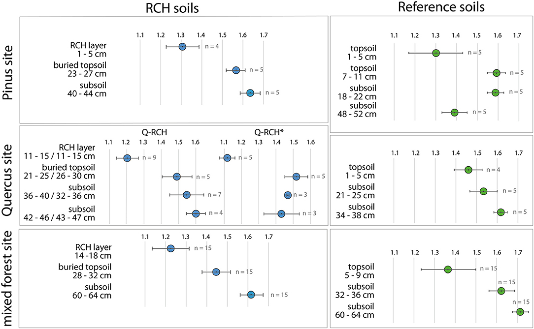
Figure 2. Bulk density (mean and standard deviation) for horizons of the charcoal hearth and reference soils for both sites, determined from undisturbed soil samples.
Water contents determined from the unwetted profiles (Table 1, Supplementary Table 1b), reflect the weather conditions before the experiments: For sites P and Q, water content is below 5% for most areas of the topsoil horizons, except for the uppermost centimeters of the technogenic deposit at the Q RCH plot, and water contents are even lower for the subsoil horizons. No clear differences appear between the water contents of sites P and Q or between the RCH and reference plots within these sites. Initial soil moisture was, however, clearly higher at site M as compared with the other sites, especially in the technogenic and topsoil horizons. Here, the water contents between the RCH and the reference plots differ, with wettest conditions in the technogenic deposit.
Water Drop Penetration Time Tests
The wdpt tests showed a very high range of water drop penetration times (Figure 3), ranging from complete infiltration in < 1 s to values of more than 3 h, and a clear relation to antecedent soil wetness conditions. Clear hydrophobic conditions were observed for the topsoil of all profiles on sites P and Q. Hydrophobicity was most persistent for the RCH sediment layer of site P, but also the topsoil and the uppermost centimeters of the subsoil showed very high water drop penetration times for this site. For site Q, hydrophobic, but also wettable and only slightly hydrophobic conditions were found in the topsoils of the RCH and the reference plot, but persistent hydrophobicity was limited to the topsoil and buried topsoil horizons. For the samples taken in early spring on site M, water drop penetration times were very short for most of the samples, and penetration times >1 min were only observed for the buried topsoil on the RCH plot.
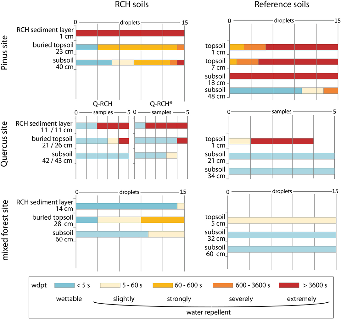
Figure 3. Distribution of water drop penetration time categories for horizons of the charcoal hearth and reference soils of both sites. Wdpt classes were determined for 15 water droplets distributed over five undisturbed samples for each horizon, with individual droplet results given for sites P and M and the wdpt category determined from the mean infiltration time of three droplets on five samples for site Q.
Dye Tracer Experiments
Infiltration of the dye tracer solution took between 6.5 and 37 min and was slower on the RCH plots for sites P and Q, but faster on the RCH plot for site M (Table 2). Tracer stains were found up to the maximum excavated depths of the profiles for all plots. Several discontinuities in the infiltration patterns were observed in all the studied profiles (Figure 4).
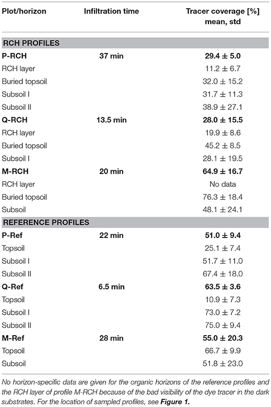
Table 2. Infiltration times for the six plots and relative tracer coverage integrated over a profile depth of 1 m (bold numbers), and over the specific horizons of each profile.
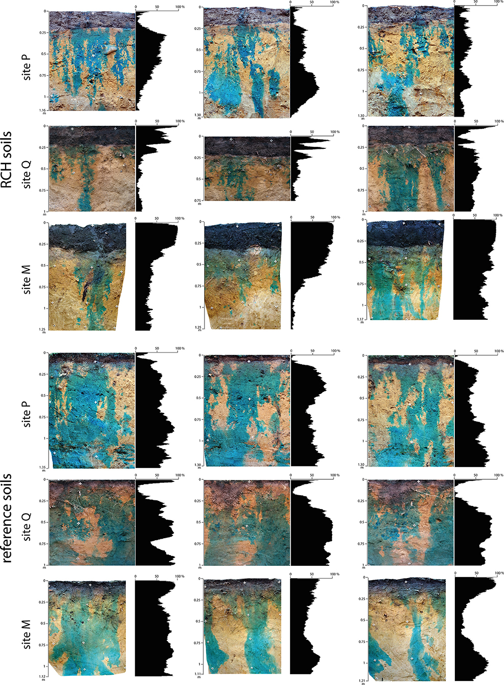
Figure 4. Dye tracer stain patterns in profile photos and plots of horizontally integrated one-dimensional vertical values of relative dye coverage vs. depth for vertical soil profiles on the four experimental plots.
In the uppermost centimeters of the profiles, it was hardly possible to distinguish wet, stained areas within the dark black organic horizons. However, tracer stains are clearly visible in the uppermost, bleached centimeters of the A horizons. For the reference soil profiles at sites P and Q, the very irregular dye coverage in this part of the profiles reflects a clear preferential infiltration through the organic horizons. Infiltration along preferential flow paths continues within the organo-mineral topsoil horizons, reflected in low dye coverage, for the Pinus and Quercus plots (Table 2). Preferential flow paths are less clear, but also observable, in the topsoil horizons at site M. Within the A horizons, both interruptions of flow and a slight vertical dispersion of the tracer stains, reflected in cone-shaped stain patterns, can be observed. No clear discontinuities in the stained flow paths appear at the boundary between the topsoil and subsoil horizons for all the reference profiles. Discontinuities in tracer staining mainly appear around the stone layers, i.e., in depths between 60 and 70 cm, where flow fingers either cease or disperse to form broader stains within the stratified loose sediment below. Dye coverage in the subsoil of all the reference profiles is relatively high, with mean coverage values between 50 and 75% for the sites (Table 2). For all reference plots, the tracer stains in the topmost areas of the subsoil are relatively large and well-connected (Figure 5). The stains decrease and become slightly fragmented in deeper parts of the subsoil below the Pinus plot but become larger and more continuous for the deeper horizontal profiles below the Quercus and mixed forest plots.
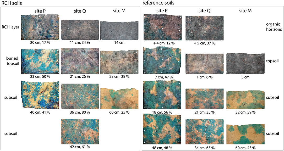
Figure 5. Dye tracer stain patterns for horizontal profiles and values of relative dye coverage integrated over the profiles. No horizon-specific quantification is given for the RCH layer and topsoil of site M, where tracer stains can hardly be distinguished from the dark substrate.
The tracer stain patterns in the RCH profiles were similar to those of the reference profiles for the topmost sections of the profiles, but clearly differed in the lower parts of the soils. For the Pinus RCH plot (Figure 4), the few stained flow paths, resulting in low dye coverage (Table 2) in the technogenic deposit can be distinguished well from the very dry substrate. Correspondingly, dye coverage was limited to relatively few stains in the horizontal profile at the lower boundary of the layer (Figure 5). Rapid vertical dispersion and an increase in dye coverage to up to 50% were observed in the buried topsoil below the RCH, which is also reflected in the horizontal profile, where tracer stains are larger and more continuous. In the subsoil, both the vertical and horizontal profiles show that the flow paths clearly separate into several very narrow and discontinuous fingers. As described for the reference profiles, these flow fingers show further discontinuities at the depths of the stone layer.
Tracer coverage patterns observed in the vertical profiles of the Quercus RCH plot were similar to those described for the Pinus RCH profiles. Infiltration through the technogenic deposit is limited to a few paths, and the dye coverage is relatively low at the bottom of this layer. The dye coverage is higher due to lateral dispersion in the buried topsoil as compared with the RCH layer. In the subsoil, a clear fragmentation of tracer stains is observable in the vertical profiles. In the subsoil horizontal profiles, the average dye coverage is relatively high; however, the stained areas can be clearly divided into small, fragmented stained areas with high color intensity and larger stained areas with low color intensity.
For the RCH profiles at site M, it is hardly possible to distinguish stained areas in the wet and therefore dark black charcoal-rich deposit. In the field, the RCH layer appeared relatively uniformly wet after the infiltration experiment, and no clear preferential flow paths were observable. A relatively continuous wetting through the RCH layer is indicated by the almost continuous dye coverage along the upper boundary of the buried topsoil horizon. Dye coverage remains very high (Table 2) all over this buried horizon, except for one profile of the mixed forest RCH plot where infiltration was affected by an old root channel. Clear discontinuities in the stained flow paths only appear in the subsoil, originating in the buried topsoil. Although less clear than observed at sites P and Q, this is reflected in a decrease of dye coverage in the horizontal profiles and in the low coverage observed in the horizontal profile. As observed for the other profiles, flow fingers in the subsoil tend to cease around the stone layer, i.e., in a depth of 60–70 cm below the ground surface.
Discussion
Bulk Density, Soil Organic Matter Contents, and Water Repellency
The bulk densities measured for the technogenic deposits associated with the RCHs were low (Figure 2), and this observation is consistent with observations on other historic RCHs (Borchard, et al., 2014; Criscuoli, et al., 2014). However, even larger differences between RCHs and reference soils have been reported. The bulk densities observed at our plots were slightly higher in the buried topsoil below the RCHs than in the topsoil horizons of the reference soils for sites P and Q. Higher density of these horizons might be caused by a physical compaction due to RCH operation. A compaction by the weight of the stacked wood is plausible, considering that the load imposed by a 3-m-high charcoal hearth is ~2,040 kg per m2, based on a weight of 680 kg (Lohman, 1998) for a 1 m3 pile of pine logs with a moisture of 25–30%. Foot traffic on the site during site preparation might further contribute to such a physical compaction. Bulk density might also be higher in consequence of a reduced bioturbation, and of lower SOM contents due to a combustion of SOM below the hearth and interrupted input of organic matter after to the burial by the technogenic deposit, as also indicated by lower LOI values (Table 1).
The persistence of hydrophobicity (Figure 3), although measured on the dry surfaces of samples under laboratory conditions, clearly varied with the antecedent wetness of the soils (Table 1), both for the RCH and for the reference plots. Under dry antecedent conditions (Pinus and Quercus site, Figure 3), the persistence of hydrophobicity was very high in the RCH substrates but also in the reference topsoils, while no or only slightly persistent hydrophobicity was observed for wet antecedent conditions (mixed forest site, Figure 3). The results are consistent with the frequently made observation that water repellency of wet, hydrophilic soil is not immediately reestablished with drying, but only after at least several days of dry conditions (Doerr et al., 2000). Results suggest seasonal variations of water repellency, governed by seasonal variations in soil moisture, both for the RCH and the undisturbed forest topsoils. The observed differences are thus consistent with the frequent observation of seasonal hydrophobicity variations, with hydrophilic conditions or low hydrophobicity observed after long wet periods and severely hydrophobic conditions during and after extended dry periods (Ritsema and Dekker, 1994; Doerr et al., 2000).
The differences in hydrophobicity observed between the sites do not show a correlation to SOM contents as reflected by LOI. While LOI values are slightly higher for site Q as compared with site M, along with a slightly higher hydrophobicity in these layers, LOI is considerably low for the extremely hydrophobic horizons of site P. Generally, direct relations between organic matter contents and the degree and persistence of water repellency have hardly been shown, and even low organic matter contents can considerably increase substrate hydrophobicity (MacGhie and Posner, 1981; Bisdom et al., 1993; Doerr et al., 2000). Relations between SOM and hydrophobicity might differ between the sites and horizons as an effect of differing plant cover, root activity, or soil fungi and microorganisms, however, such interactions are hardly understood by now and could not be assessed within this study.
The very high range of water drop penetration times found for the RCH layer of site Q, with either extremely short or extremely long times until water drop infiltration, might be caused by the high spatial heterogeneity of the substrate with local concentrations of hydrophobic charcoal fragments or SOM; or by a high heterogeneity of antecedent wetness in this layer. Water drop penetration times of the buried topsoils do not generally reflect higher water repellency as compared with the reference topsoils, and therefore do not indicate increased hydrophobicity associated with heating of the soil. However, water drop penetration times were found to differ between the buried and the reference topsoils for all sites. For sites P and Q, hydrophobicity in the reference profile topsoils was higher as compared with the buried topsoils, which might be related to SOM contents and composition in the reference horizons and to a more uniform drying of the reference topsoils near the surface as compared with the buried topsoils in depths of about 30 cm in the RCH profiles. For site M, persistence of hydrophobicity was found in the buried topsoil as compared with the reference topsoil, which does not relate to higher LOI in this horizon but can possibly be caused by a more uniform wetting of the near-surface reference horizon during a wet antecedent period.
Overall, no clear differences in the persistence of hydrophobicity were determined for RCH and reference samples, however, it needs to be considered that hydrophobic behavior affects considerably larger parts of the soil profiles on RCHs, with strong water repellency occurring in the upper 30 cm of the soil on these sites, but usually only in the topmost centimeters on reference soils.
Preferential Flow Patterns
The infiltration patterns observed in the dye tracer experiments show only slight differences in the uppermost horizons of the RCH and the reference plots (Figure 4). Infiltration through the technogenic deposits associated with the RCHs was concentrated along very few preferential flow paths under dry conditions. The dye patterns are furthermore highly irregular in this layer, i.e., abrupt changes between relatively broad and narrow stains were noted, which can be interpreted as indicating abrupt changes between fingered flow in a heterogeneous soil matrix and macroporous flow (Weiler and Flühler, 2004). These infiltration patterns are most probably related to a high spatial heterogeneity of pore volumes in this layer, associated with the heterogeneous distribution of large charcoal fragments, and to a spatial heterogeneity of hydrophobicity related to the distribution of SOM and charcoal fragments. Tracer staining is also limited to a few preferential flow paths in the organic horizons (L/Of/Oh) of the reference profiles. The flow patterns in this layer can be interpreted as the result of preferential flow through macropores in the hydrophobic organic material. For the interpretation of stain patterns on site P, it needs to be considered that profiles on plot P-RCH were excavated and documented on the same day that the tracer solution was applied, but the profiles associated with plot P-Ref were documented on the next day, so that the infiltrating dye solution might have spread further, forming larger stain patterns for the reference soil plot. However, even higher differences in tracer coverage were found for plots at site Q, where time between infiltration and excavation was one whole day for both plots.
In the RCH profiles of site M, infiltration in the technogenic horizon appears more homogeneous with less clear indications for preferential flow, reflecting a breakdown of the substrate's hydrophobicity in wet conditions. Although tracer coverage in the dark black substrate could hardly be quantified, observations from the field and the almost continuous dye coverage observed in the upper part of the buried topsoil indicate that in this situation, the high porosity and low continuity of pores in the technogenic substrate favor a uniform wetting of the RCH layer. Resulting from this effect, and probably enforced by lateral spreading of infiltrating water, dye coverage is also high in the buried topsoil below the RCH.
The variation of preferential flow observed in the experiments reflects variations in water repellency, with persistent hydrophobicity under dry conditions as in the autumn experiments and smaller hydrophobicity effects under wet, early spring conditions. Higher preferential flow in autumn might also be related to a higher spatial heterogeneity of initial soil moisture, due to heterogeneous initial wetting after dry conditions and a heterogeneous water uptake by roots. This is similarly noted by Hangen et al. (2004), who also observed that lower areas of mine spoil soil profiles studied in a lysimeter experiment were participating in drainage in autumn drainage events, as compared with events in early spring.
For all RCH profiles, irrespective of the initial soil moisture, lateral dispersion of infiltrating water resulting in an increase in the stained area and larger, horizontally connected stains (Figure 5), was observed in the buried topsoils. The lateral dispersion of the tracer solution in these horizons might be caused by a relatively homogeneous soil matrix and a relatively low hydraulic conductivity in the vertical direction, resulting from compaction or reduced bioturbation effects and therefore decreased pore continuity. The lower degree of infiltration along preferential flowpaths, as compared with the reference topsoils, might further be affected by a reduced input of hydrophobic organic compounds after burial of the horizon.
Although the differences in the stain patterns developed in the uppermost horizons of the profiles at sites P and Q were to some extent compensated for by lateral dispersion in the topsoils, distinct differences appeared immediately below the topsoils at both sites. For the reference soil profiles, the shapes of the stain patterns and the relative dye coverage were similar in the topsoils and the subsoil; however, the stains became considerably smaller and more fragmented at greater depths below the RCH plots (Figure 5). This reduction and fragmentation of the wetted area below the RCHs persisted over the whole depth of the studied profiles. The stain patterns observed for the reference soil profiles are similar to the preferential flow patterns seen in water-repellent sandy soils, such as the dune sand soils in the Netherlands, which have previously been described and analyzed in detail (Dekker and Ritsema, 2000; Ritsema and Dekker, 2000). Although less clear, a similar pattern with more fragmented stains in the RCH subsoil and broader flow fingers in the reference profile subsoil were observed for the mixed forest site. No clear differences in the average wetted area are observable here, as the variation between the three profiles of each site is higher than the difference between the sites (Table 2). However, the horizontal profile in the subsoil still shows lower dye coverage with smaller, more fragmented stains (Figure 5). The differences in the infiltration patterns between the RCH and reference subsoils cannot be related to the basic soil properties determined in this study. Generally, the differences in preferential flow below the RCH sites might result from differences in the pore system. Our subsoil samples do not indicate an overall lower porosity for the RCH sites, but disturbances to pore continuity or modification of the pore size distribution to a smaller proportion of marcropores due to mechanical pressure during charcoal production are possible. The separation of the flow into distinct, narrow fingers below the buried topsoil horizons might also be due to unstable flow mechanisms related to differences in permeability and conductivity between the buried topsoils and the subsoils below the RCHs (Hendrickx and Flury, 2001). A similar initiation of preferential flow in the subsoil has been described for structural interfaces between plow layers and the subsoil on tilled sandy and sandy loam soils (Ghodrati et al., 1990; Petersen et al., 2001).
Discontinuities in the flow at the two stone layers and the lateral spreading of the tracer solution in the layered sediment below were observed in all profiles. The interruptions in flow at the stone layers can be interpreted as a result of a capillary barrier effect caused by the presence of these coarser layers within the fine sandy sediment (Kung, 1990). The lateral dispersion seen in the deeper parts of the profile is most likely due to the high permeability of the relatively coarse soil matrix and to the horizontal stratification of the sediment. Although the flow instabilities at the stone layers and within the stratified sediments are similar for all the profiles, differences in the relative dye coverage established in the upper parts of the subsoil persist through the deepest parts of the investigated profiles.
Summary and Conclusions
The results of the dye tracer experiments performed in our study reflect differences in infiltration behavior between undisturbed forest soils and RCH soils, and differences in infiltration behavior of RCH soils between wet and dry antecedent conditions. Infiltration along preferential flow paths, related to the high structural heterogeneity of the substrate, was observed for all profiles.
Under dry conditions, a very high degree of preferential flow and therefore increased heterogeneity of soil wetness were noted for RCH soils, mainly due to the relatively thick technogenic layer with a high structural heterogeneity and persistence of hydrophobicity, and probably also to unstable flow mechanisms on the additional layer boundary in the profile. For wet conditions, hydrophobicity effects are clearly diminished, resulting in a more uniform wetting of the technogenic deposits. These results affirm that preferential flow effects can show a high temporal variation, most probably related to variations in soil moisture and hydrophobicity. The results further affirm that hydrophobicity does not only depend on concurrent initial soil moisture but are also dependent on antecedent wetness conditions in the period before an infiltration event.
Because of the high thickness of the technogenic layer affected by temporal variations of preferential infiltration, RCH soils can show a high temporal variability of soil moisture in the upper 20–40 cm of the soil profile. Because large parts of the technogenic horizon remain dry as a consequence of the highly preferential flow under dry antecedent conditions, conditions for plant growth in the uppermost parts of the profiles can be assumed to be worse during and after dry periods. In wet periods, conditions might be improved because of the thickness of the high-porosity and relatively uniformly wetted RCH layer, however, this can hardly be concluded without a more detailed knowledge on the porosity and pore size distribution of this substrate. Overall, the results confirm that soil properties and ecological site conditions can clearly be affected by historic land use, even in areas with continuous forest cover.
Author Contributions
AS and FH planned and carried out field and laboratory work. AS carried out image analysis and drafted the manuscript. All authors discussed the results and contributed to the final manuscript.
Conflict of Interest Statement
The authors declare that the research was conducted in the absence of any commercial or financial relationships that could be construed as a potential conflict of interest.
Acknowledgments
This study was supported by the Deutsche Forschungsgemeinschaft DFG in the project SCHN 1349/(1-1). We thank Bastian Pötzsch (bachelor student at BTU Cottbus-Senftenberg) for contributing to field and laboratory work, Vattenfall Europe Mining AG for providing an ALS elevation model and aerial photograph, and the Landesbetrieb Forst Brandenburg for providing access to the sites.
Supplementary Material
The Supplementary Material for this article can be found online at: https://www.frontiersin.org/articles/10.3389/fenvs.2018.00143/full#supplementary-material
References
Ad-hoc-AG Boden (2005). Bodenkundliche Kartieranleitung. Hannover: Bundesanstalt für Geowissenschaften und Rohstoffe.
Allaire, S. E., Roulier, S., and Cessna, A. J. (2009). Quantifying preferential flow in soils, a review of different techniques. J. Hydrol. 378, 179–204. doi: 10.1016/j.jhydrol.2009.08.013
Andreini, M. S., and Steenhuis, T. S. (1990). Preferential paths of flow under conventional and conservation tillage. Geoderma 46, 85–102. doi: 10.1016/0016-7061(90)90009-x
Badorreck, A., Gerke, H. H., and Vontobel, P. (2010). Noninvasive observations of flow patterns in locally heterogeneous mine soils using neutron radiation. Vadose Zone J. 9, 362–372. doi: 10.2136/vzj2009.0100
Beven, K., and Germann, P. (1982). Macropores and water flow in soils. Water Res. Res. 18, 1311–1325. doi: 10.1029/WR018i005p01311
BGR (2015). Bodenübersichtskarte CC4750. Hannover: Bundesanstalt für Geowissenschaften und Rohstoffe.
Bisdom, E. B. A., Dekker, L. W., and Schoute, J. F. (1993). Water repellency of sieve fractions from sandy soils and relationships with organic material and soil structure. Geoderma 56, 105–118. doi: 10.1016/0016-7061(93)90103-R
Bond, J. (2007). “Medieval charcoal-burning in England,” in Arts and Crafts in Medieval Rural Environment, eds J. Klapste and P. Sommer (Turnhout: Brepols Publishers), 277–294.
Borchard, N., Ladd, B., Eschemann, S., Hegenberg, D., Moseler, B. M., and Amelung, W. (2014). Black carbon and soil properties at historical charcoal production sites in Germany. Geoderma 232, 236–242. doi: 10.1016/j.geoderma.2014.05.007
Buras, A., Hirsch, F., van der Maaten, E., Takla, M., Räbiger, C., Cruz Garcia, R., et al. (2015). Charcoal kiln relicts - a favorable site for tree growth? Geophy. Res. Abstr. 17:EGU2015-3257-1.
Carrari, E., Ampoorter, E., Verheyen, K., Coppi, A., and Selvi, F. (2016). Former charcoal kiln platforms as microhabitats affecting understorey vegetation in Mediterranean forests. Appl. Veg. Sci. 19, 486–497. doi: 10.1111/avsc.12238
Chidumayo, E. N., and Gumbo, D. J. (2013). The environmental impacts of charcoal production in tropical ecosystems of the world. A synthesis. Energy Sust. Dev. 17, 86–94. doi: 10.1016/j.esd.2012.07.004
Criscuoli, I., Alberti, G., Baronti, S., Favilli, F., Martinez, C., Calzolari, C., et al. (2014). Carbon sequestration and fertility after centennial time scale incorporation of charcoal into soil. PLoS ONE 9:e91114. doi: 10.1371/journal.pone.0091114
Criscuoli, I., Baronti, S., Alberti, G., Rumpel, C., Giordan, M., Camin, F., et al. (2017). Anthropogenic charcoal-rich soils of the XIX century reveal that biochar leads to enhanced fertility and fodder quality of alpine grasslands. Plant Soil 411, 499–516. doi: 10.1007/s11104-016-3046-3
Dekker, L. W., and Jungerius, P. D. (1990). Water repellency in the dunes with special reference to The Netherlands. Catena. Suppl. 18. 173–183.
Dekker, L. W., and Ritsema, C. J. (2000). Wetting patterns and moisture variability in water repellent Dutch soils. J. Hydrol. 231–232, 148–164. doi: 10.1016/S0022-1694(00)00191-8
Doerr, S. H. (1998). On standardizing the ‘water drop penetration time' and the ‘molarity of an ethanol droplet' techniques to classify soil hydrophobicity. A case study using medium textured soils. Earth Surf. Proc. Landf. 23, 663–668.
Doerr, S. H., Shakesby, R. A., and Walsh, R. P. D. (2000). Soil water repellency. its causes, characteristics and hydro-geomorphological significance. Earth Sci. Rev. 51, 33–65. doi: 10.1016/S0012-8252(00)00011-8
Droogers, P., Stein, A., Bouma, J., and de Boer, G (1998). Parameters for describing soil macroporosity derived from staining patterns. Geoderma 83, 293–308. doi: 10.1016/S0016-7061(98)00005-6
Flury, M., and Flühler, H. (1994). Brilliant Blue FCF as a dye tracer for solute transport studies—a toxicological overview. J. Environ. Q. 23, 1108–1112.
Flury, M., and Flühler, H. (1995). Tracer characteristics of brilliant blue FCF. Soil Sci. Soc. Am. J. 59, 22–27.
Flury, M., Flühler, H., Jury, W. A., and Leuenberger, J. (1994). Susceptibility of soils to preferential flow of water, a field study. Water Res. Res. 30, 1945–1954. doi: 10.1029/94WR00871
Friedrich, P. K. II. (1779). Verordnung, Wie es mit dem Holzschlag zu Kohlen und Köhlereyen bei den Königlichen Eisen = Blech = Kupfer = und Auch Anderen Hütten = und Hammerwerken Gehalten Werden Soll. De Dato Berlin. Brandenburgisches Landeshauptarchiv, Pr. Br. Rep. 2A III F Regierung Potsdam, Holzkohlen-S. Kohlenschwelen in den kgl. Forsten und Holzschlag für Köhlereien bei den kgl. Hütten- und Hammerwerken (1738–1849), F.5-12.
Gerke, H. H. (2006). Preferential flow descriptions for structured soils. J. Plant Nutr. Soil Sci. 169, 382–400. doi: 10.1002/jpln.200521955
Gerke, H. H., Badorreck, A., and Einecke, M. (2009). Single- and dual-porosity modelling of flow in reclaimed mine soil cores with embedded lignitic fragments. J. Cont. Hydrol. 104, 90–106. doi: 10.1016/j.jconhyd.2008.10.009
Ghodrati, M., Ernst, F. F., and Jury, W. A. (1990). Automated spray system for application of solutes to small field plots. Soil Sci. Soc Am. J. 54, 287–290. doi: 10.2136/sssaj1990.03615995005400010046x
Groenewoudt, B. (2007). Charcoal burning and landscape dynamics in the early medieval Netherlands. Ruralia 6, 327–337.
Hangen, E., Gerke, H. H., Schaaf, W., and Hüttl, R. F. (2004). Flow path visualization in a lignitic mine soil using iodine–starch staining. Geoderma 120, 121–135. doi: 10.1016/j.geoderma.2003.08.011
Hardy, B., Cornelis, J. T., Houben, D., Lambert, R., and Dufey, J. E. (2016). The effect of pre-industrial charcoal kilns on chemical properties of forest soil of Wallonia, Belgium. Eur. J. Soil Sci. 67, 206–216. doi: 10.1111/ejss.12324
Hart, J. L., van de Gevel, S. L., Mann, D. F., and Clatterbuck, W. K. (2008). Legacy of charcoaling in a Western Highland Rim Forest in Tennessee. Am. Midland Nat. 159, 238–250. doi: 10.1674/0003-0031(2008)159[238:LOCIAW]2.0.CO;2
Hartge, R., and Horn, R. (2009). Die physikalische Untersuchung von Böden. Stuttgart: Praxis Messmethoden Auswertung. Schweizerbart Verlag.
Hendrickx, J. M. H., Dekker, L. W., and Boersma, O. H. (1993). Unstable wetting fronts in water-repellent field soils. J. Environ. Q. 22, 109–118. doi: 10.2134/jeq1993.00472425002200010014x
Hendrickx, J. M. H., and Flury, M. (2001). “Uniform and preferential flow mechanisms in the vadose zone,” in Conceptual Models of Flow and Transport in the Fractured Vadose Zone (Washington, DC: The National Academies Press), 149–187.
Hirsch, F., Raab, T., Ouimet, W., Dethier, D., Schneider, A., and Raab, A. (2017). Soils on historic charcoal hearths, terminology and chemical properties. Soil Sci. Soc Am. J. 81, 1427–1435. doi: 10.2136/sssaj2017.02.0067
Hirsch, F., Schneider, A., Bauriegel, A., Raab, A., and Raab, T. (2018). Formation, classification and properties of soils at two relict charcoal hearth sites in Brandenburg, Germany. Front. Environ. Sci. 6:94. doi: 10.3389/fenvs.2018.00094
Inbar, A., Lado, M., Sternberg, M., Tenau, H., and Ben-Hur, M. (2014). Forest fire effects on soil chemical and physicochemical properties, infiltration, runoff, and erosion in a semiarid Mediterranean region. Geoderma 221–222, 131-138. doi: 10.1016/j.geoderma.2014.01.015
Kasse, C., Vandenberghe, D., de Corte, F., and van den Haute, P. (2007). Late Weichselian fluvio-aeolian sands and coversands of the type locality Grubbenvorst (southern Netherlands), sedimentary environments, climate record and age. J. Q. Sci. 22, 695–708. doi: 10.1002/jqs.1087
Kerrè, B., Willaert, B., Cornelis, Y., and Smolders, E. (2017). Long-term presence of charcoal increases maize yield in Belgium due to increased soil water availability. Eur. J. Agron. 91, 10–15. doi: 10.1016/j.eja.2017.09.003
Kinney, T. J., Masiello, C. A., Dugan, B., Hockaday, W. C., Dean, M. R., Zygourakis, K., Barnes, R., et al. (2012). Hydrologic properties of biochars produced at different temperatures. Biomass Bioenerg. 41, 34–43. doi: 10.1016/j.biombioe.2012.01.033
Knapp, H., Nelle, O., and Kirleis, W. (2015). Charcoal usage in medieval and modern times in the Harz Mountains Area, Central Germany. Wood selection and fast overexploitation of the woodlands. Q. Int. 366, 51–69. doi: 10.1016/j.quaint.2015.01.053
Ko, D. W., Sparrow, A. D., and Weisberg, P. J. (2011). Land-use legacy of historical tree harvesting for charcoal production in a semi-arid woodland. Forest Ecol. Manage. 261, 1283–1292. doi: 10.1016/j.foreco.2011.01.007
Krause, S., and Möseler, B. M. (1993). Vegetationskundliche und standortökologische Untersuchungen an einem ehemaligen Meilerplatz im Kermeter (Nordeifel). Dechenia 146, 91–95.
Kung, K. J. S. (1990). Preferential flow in a sandy vadose zone. 2. Mechanism and implications. Geoderma 46, 59–71. doi: 10.1016/0016-7061(90)90007-V
MacGhie, D. A., and Posner, A. M. (1981). The effect of plant top material on the water repellence of fired sands and water-repellent soils. Austr. J. Agric. Res. 32, 609–620. doi: 10.1071/AR9810609
Mastrolonardo, G., Francioso, O., and Certini, G. (2018). Relict charcoal hearth soils, a neglected carbon reservoir. Case study at Marsiliana forest, Central Italy. Geoderma 315, 88–95. doi: 10.1016/j.geoderma.2017.11.036
Mikan, C. J., and Abrams, M. D. (1995). Altered forest composition and soil properties of historic charcoal hearths in southeastern Pennsylvania. Can. J. Forest Res. 25, 687–696.
Petersen, C. T., Jensen, H. E., Hansen, S., and Bender Koch, C. (2001). Susceptibility of a sandy loam soil to preferential flow as affected by tillage. Soil Till. Res. 58, 81–89. doi: 10.1016/S0167-1987(00)00186-0
Potsdam-Institut für Klimafolgenforschung. (2009). Walterdiagramm Peitzer Teiche (FFH 4152-302). Available online at: http://www.pik-potsdam.de/~wrobel/sg-klima-3/landk/popups/l3/sgd_t3_1009.html
Pusceddo, E., Montanaro, A., Fioravanti, G., Santilli, S. F., Foscolo, P. U., Criscuoli, I., et al. (2017). Comparison between ancient and fresh biochar samples, a study on the recalcitrance of carbonaceous structures during soil incubation. Int. J. N. Technol. Res. 3, 39–46.
R Core Team (2017). R: A Language and Environment for Statistical Computing. Vienna: R Foundation for Statistical Computing. Available online at: URL http://www.R-project.org/
Raab, A., Bonhage, A., Schneider, A., Raab, T., Rösler, H., Heußner, K.-U., et al. (2017). Spatial distribution of relict charcoal hearths in the former royal forest district Tauer (SE Brandenburg, Germany). Q. Int. doi: 10.1016/j.quaint.2017.07.022
Raab, A., Takla, M., Raab, T., Nicolay, A., Schneider, A., Rösler, H., et al. (2015). Pre-industrial charcoal production in Lower Lusatia (Brandenburg, Germany). Detection and evaluation of a large charcoal-burning field by combining archaeological studies, GIS-based analyses of shaded-relief maps and dendrochronological age determination. Q. Int. 367, 111–122. doi: 10.1016/j.quaint.2014.09.041
Raab, T., Hirsch, F., Oiumet, W., Johnson, K., Dethier, D., and Raab, A. (2017). Architecture of relict charcoal hearths in northwestern Connecticut, USA. Geoarchaeology 32, 504–510. doi: 10.1002/gea.21614.
Rasband, W. S. (2012). ImageJ. Available online at: http://imagej.nih.gov/ij/
Ritsema, C. J., and Dekker, L. W. (1994). How water moves in a water repellent sandy soil: 2. Dynamics of fingered flow. Water Res. Res. 30, 2519–2531. doi: 10.1029/94WR00750
Ritsema, C. J., and Dekker, L. W. (2000). Preferential flow in water repellent sandy soils. principles and modeling implications. J. Hydrol. 231–232, 308–319. doi: 10.1016/S0022-1694(00)00203-1
Rösler, H. (2008). Köhlerei für das Eisenhüttenwerk Peitz in Brandenburg. Arch. Deutschland 3, 36–37.
Rösler, H., Bönisch, E., Schopper, F., Raab, T., and Raab, A. (2012). “Pre-industrial charcoal production in southern Brandenburg and its impact on the environment,” in Landscape Archaeology between Art and Science, eds S. Kluiving and E. Guttmann-Bond (Amsterdam: Amsterdam University Press), 167–178.
Stolz, C., Böhnke, S., and Grunert, J. (2012). Reconstructing 2500 years of land use history on the Kemel Heath (Kemeler Heide), southern Rhenish Massif, Germany. EG Q. Sci. J. 61, 169–183. doi: 10.23689/fidgeo-1783
Weiler, M., and Flühler, H. (2004). Inferring flow types from dye patterns in macroporous soils. Geoderma 120, 137–153. doi: 10.1016/j.geoderma.2003.08.014
Keywords: relict charcoal hearths, land use legacies, water repellency, preferential flow, dye tracer experiments
Citation: Schneider A, Hirsch F, Raab A and Raab T (2018) Dye Tracer Visualization of Infiltration Patterns in Soils on Relict Charcoal Hearths. Front. Environ. Sci. 6:143. doi: 10.3389/fenvs.2018.00143
Received: 08 August 2018; Accepted: 08 November 2018;
Published: 27 November 2018.
Edited by:
Philippe C. Baveye, AgroParisTech Institut des Sciences et Industries du Vivant et de L'environnement, FranceReviewed by:
Zamir Libohova, United States Department of Agriculture, United StatesBrieuc Hardy, Walloon Agricultural Research Centre, Belgium
Copyright © 2018 Schneider, Hirsch, Raab and Raab. This is an open-access article distributed under the terms of the Creative Commons Attribution License (CC BY). The use, distribution or reproduction in other forums is permitted, provided the original author(s) and the copyright owner(s) are credited and that the original publication in this journal is cited, in accordance with accepted academic practice. No use, distribution or reproduction is permitted which does not comply with these terms.
*Correspondence: Anna Schneider, anna.schneider@b-tu.de