Mechanical mechanism of rock mass slabbing aggravating toppling failure
 Junchao Cai
 Shuqiang Lu4*
 - 1School of Civil Engineering, Henan University of Science and Technology, Luoyang, China
- 2State Key Laboratory of Geohazard Prevention and Geoenvironment Protection, Chengdu University of Technology, Chengdu, China
- 3Fujian Key Laboratory of Geohazard Prevention, Fuzhou, China
- 4Key Laboratory of Geological Hazards on Three Gorges Reservoir Area (China Three Gorges University), Ministry of Education, Yichang, China
- 5Chengdu East Group Co., Ltd, Chengdu, China
- 6Shuifa Planning and Design Limited Company, Jinan, China
Many slabbing rock masses have emerged in hydropower slopes and underground engineering, with the construction of basic engineering and resource development projects along the zone of the Belt and Road. The anti-dip slabbing rock mass is prone to toppling and the degree of slabbing controls the development of toppling deformation. There are a few reports on the mechanical mechanism of rock mass toppling deformation after slabbing. Based on the analysis of the genetic conditions of rock mass slabbing, the influence of rock mass after slabbing on toppling deformation was explored by means of the mechanics method. The toppling bending deflection (TBD) and the toppling fracture depth (TFD) were selected as the analysis indexes, and the response regularity of slabbing on toppling rock mass was analyzed with examples. The results show that the width and thickness of the slabbing rock mass become narrower and thinner, the toppling bending deflection (TBD) increases, the toppling fracture depth (TFD) decreases, and the toppling deformation and failure intensify. The TBD is independent of the width of rock mass slabbing under self-weight, and the change of TBD is slow when the slab beam slabbing number (n) of thickness is <4 and fast when the slabbing number is above 4. The first TFD decreases fast when w is <2.0 m and it tends to be stable when w is above 2.0 m. The first TFD reduces relatively fast with the decrease in the thickness (t) of the slab beam. The result of this study can provide a reference for the treatment and evaluation of slabbing rock mass toppling deformation.
1. Introduction
With the implementation of the Belt and Road strategy, many infrastructure projects and resource development projects along the zone have been put into construction. The excavation of hydropower slopes, hydropower underground chambers, and deep tunnels exposes a large number of rock mass slabbing failures (Wu et al., 2010; Sun et al., 2012; Qiu et al., 2014; Zhou et al., 2015; Liu et al., 2017; Zhou et al., 2018; Qin et al., 2020; Xu et al., 2021; Fujii et al., 2022).
The rock mass with slab fracture structure is divided by fracture surfaces (slab fracture surfaces) that are nearly parallel to a certain extent. The rock mass among the slab fracture surfaces presents a slab-like feature. The slabbing rock mass structure is called the slab fracture structure. The slabbing failure rock mass consists of a slab fracture structure formed by excavation unloading of intact rock mass, relatively intact rock mass, and massive rock mass, and a natural slab fracture structure formed by long-term geological processes. Due to the difference in output characteristics of the slab fracture rock mass, the rock slab with anti-dip characteristics is prone to toppling deformation and failure, which are common in hydropower, traffic engineering slopes, hydropower buildings, and tunnels (Goodman, 2013). Toppling failure has been reported in more and more situations with the construction of mines, highways, hydropower stations, and so on. Many scholars have carried out research on the evolution mechanism of toppling failure and identification of instability failure (Huang, 2008; Huang et al., 2017; Tao et al., 2019; Bao et al., 2022; Nie et al., 2022; Zhu et al., 2022; Li et al., 2022a). The cantilever beam theory was introduced to study the rock mass with slab fracture structure (Goodman and Bray, 1976; Sun and Zhang, 1985; Aydan and Kawamoto, 1992; Amini et al., 2009, 2012; Liu H. J. et al., 2016; Alejano et al., 2018; Zheng et al., 2018; Cai et al., 2022a). Ni and Ye (1987) compared and analyzed the similarities and differences between the slab fracture structure rock mass and the layered rock mass, and concluded that the failure forms of the slab fracture structure are flexural toppling failure and buckling instability. Many scholars have carried out research on the slabbing rock mass and its genetic mechanism and achieved fruitful results. Some scholars analyzed the characteristics of slope rock mass slabbing under different stress modes caused by valley undercutting, excavation, and long-term geological processes from the perspective of supergene transformation and aging deformation (Huang et al., 1994; Tao et al., 2000; Huang, 2008; Huang et al., 2017; Cai et al., 2019; Liang et al., 2022; Li et al., 2022b). The latest research show that a large number of slabbing failures have also emerged in the excavation of underground chambers and tunnels (Du et al., 2016; Gong et al., 2018, 2020; Pan et al., 2020; Jiang et al., 2021; He et al., 2022; Tang et al., 2022; Wang et al., 2022). Huang (2008) and Huang et al. (2017) proposed the three stages of the development process of high slope and the characteristics of slope stress field with undercutting or excavation unloading, which is of great significance to reveal the causes of rock mass slabbing under stress conditions at different development stages of the slope and also deepen the understanding of rock mass slabbing phenomena exposed by the excavation of deep tunnels and hydropower underground chambers.
Slabbing transformed the toppled rock mass, making the original rock slab and rock block thinner and narrower. The mechanical strength parameters (rock block and structural plane) are reduced due to long-term geological action, which further aggravates the degree of rock mass toppling deformation, indicating that the occurrence of toppling deformation is closely related to the mechanical and geometric characteristics of the rock slab. There are few reports on the regularity and mechanical mechanism of rock mass toppling deformation after slabbing. This study mainly analyzes the geometric size of the rock slab of the toppled rock mass after slabbing, which is mainly reflected in the influence of the width and thickness of the rock slab. Based on the causes analysis of rock mass slabbing, this study uses mechanical methods to analyze the mechanical mechanism by which rock mass slabbing aggravates toppling deformation and explains its influence degree from two aspects: the toppling bending deflection (TBD) and the toppling fracture depth (TFD), and analyzes the influence law of rock mass slabbing on toppling deformation with examples.
2. Genetic condition of rock mass slabbing
The rock mass slabbing process of slope can be described as follows: the stress redistribution of slope caused by valley undercutting or engineering excavation, and the difference of unloading rebound value caused by the difference of rock mass structure, lithological composition, and mechanical properties produces tensile stress and shear stress concentrations within the unloading influence depth range. The stress differentiation makes the tensile stress concentration zone produce a tension fracture surface, and the compressive stress concentration area forms shear- and compression-induced tension fracture surfaces, which are nearly parallel to the unloading surface (Figures 1, 2). With the late transformation, the rock mass with the slab fracture structure has further deteriorated. The different cutting combination relationship between the slab fracture structure rock mass and the slope surface or free face where it is located forms the types of slope such as anti-dip slope, dip slope, and oblique slope, and the toppling bending deformation occurs on the anti-dip slope under the influence of external factors and self-weight (Huang et al., 1994; Huang, 2008; Huang et al., 2017). Meanwhile, considering the rheological properties of rock mass, the deterioration of rock mass properties caused by water and weathering and the toppling deformation of the anti-dip rock slope intensified.
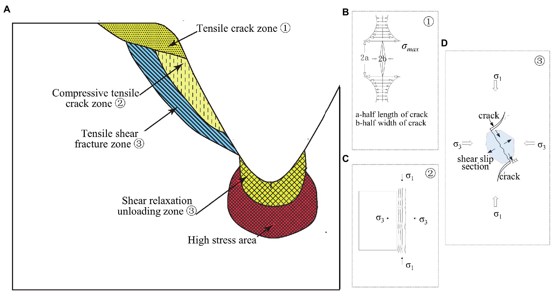
Figure 1. Rock mass slabbing of slope under different stress states.
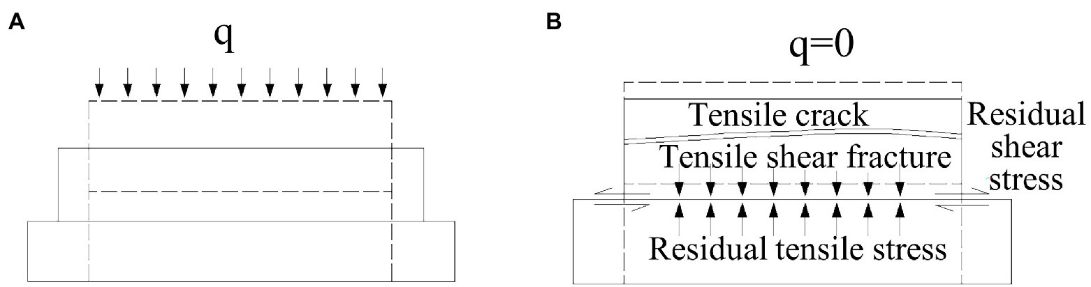
Figure 2. Differential resilience of rock strength differences. (A) loading and (B) unloading.
The rock mass slabbing is the result of the combined action of internal and external factors. The internal factors are the decisive condition, and the external factors play the role of triggering and inducing. The internal factors include the mineral composition characteristics and internal structure of rocks. The external factors include stress state, excavation, earthquake, weathering, and other deterioration factors.
2.1. Internal defect of rock mass
Mineral particles constitute the rock, and the boundary between mineral particles and the trace cutting through mineral particles are the places where subtle cracks (such as cracks, small weak surfaces, and other defects) are generated. The size, arrangement, and combination of mineral particles in the rock and the connection between particles are the internal factors of rock mass slabbing. The anisotropy of rock caused by the directional arrangement of mineral particles determines the dominant orientation of the slab fracture surface. When the condition of stress concentration is sufficient, the rock will undergo intergranular fracture, Peristaline fracture, and cleavage transgranular fracture. With the increase of deformation, the rock will undergo microcracks to slab fracture. Therefore, the grain arrangement and internal defects lay the material structure foundation for the rock mass slabbing and affect the development direction and degree of rock mass slabbing.
2.2. External environmental factors
The external factors that affect the rock mass slabbing mainly include stress state (stress differentiation and differential unloading), weathering, water action, earthquake (dynamic load), and human activities.
Slabbing of rock mass may be caused by valley undercutting and excavation of slope, chamber, etc. The stress state of rock mass transits from the initial compression state to the tensile state. The stress state goes through compression, shear, and tension (Figure 1). Under various mechanical behaviors, the rock mass deteriorates into a slab-like rock mass. The tension, shear, and compression generated in the stress differentiation and the difference in rock mass material properties lead to the differential unloading rebound, and the stress concentration and residual stress occur in the rock mass within a certain range of the unloading surface, intensifying the slabbing failure (Figure 2).
In addition to the influence of the change of stress state on rock mass slabbing, weathering, earthquake, water, and human activities, all promote the occurrence of slabbing and further fragmentation and deterioration of slabbing rock mass.
1. Under the weathering of minerals and rocks, the connection degree of particles in the rock mass, the undulation and roughness of slab fracture surface weaken, the overall strength decreases, and the porosity increases, further providing a channel for the action of water.
2. In the process of stress wave propagation under dynamic load, the reflection will occur at the relatively free interface with different medium characteristics. At the interface, the incident wave will generate a tensile wave (tensile stress), and the greater the difference in elastic modulus between the two mediums, the greater the tensile stress. The cumulative effect of repeated dynamic loads aggravates the development of rock mass slabbing.
3. The water combines with the hydrophilic substances on the slab fracture surface for lubrication, or some minerals on the slab fracture surface will be hydrolyzed and dissolved. The expansion of frozen volume, hydrostatic pressure, and hydrodynamic pressure of water in the slab fracture surface will further aggravate the expansion of fractures.
4. The excavation and reconstruction of human activities provide free space for unloading and forming slabbing. The blasting, vibration, and other artificial dynamic loads will further trigger and intensify the rock mass slabbing.
3. Slabbing effect of toppling deformation based on bending deflection
3.1. Mechanical model analysis
The influence of rock mass slabbing under self-gravity on toppling bending deflection (TBD) is considered. The thickness and width of the rock slab are reduced due to slabbing, and the adhesion between the slab fracture surfaces is lost or decreased due to various factors, which makes it easier to produce interlaminar dislocation in the process of toppling and bending.
Before rock mass slabbing, the toppling bending deflection (TBD) caused by the self-weight is estimated by Equation 1. After rock mass slabbing, the flexural stiffness of the rock slab decreases greatly and the toppling bending deflection (TBD) increases significantly. It is assumed that the slabbing of the isothick slab in rock formation forms n layer m segment (Figure 3), and then the toppling bending deflection (TBD) caused by the bending moment provided by the self-weight is estimated by Equation 2 as follows:
where α is the dip angle of the rock beam, l is the length of the cantilever beam segment, t is the thickness of the beam, r is the beam weight, and E is the deformation modulus of the slabbing rock mass. It can be seen from Equation 2 that the toppling bending deflection (TBD) of the rock slab increases after the rock mass slabbing. Moreover, the more serious the rock mass slabbing is, the more severe the toppling flexural stiffness of the rock slab is reduced, and the more easily the rock slab is inclined to topple and bend. Then, the toppling deformation will develop gradually and enter the creeping stage considering the time effect (Cai et al., 2022b).
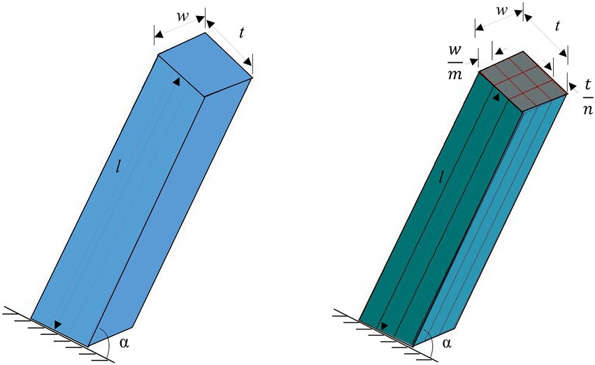
Figure 3. Relative loading conditions of rock beams before and after slabbing. Left: before slabbing; Right: after slabbing.
Considering the particularity of rock lithology, there will be a tension-neutral layer not located on the geometric central axis of its section. There is a difference between the deformation and the assumption (Figures 4, 5).
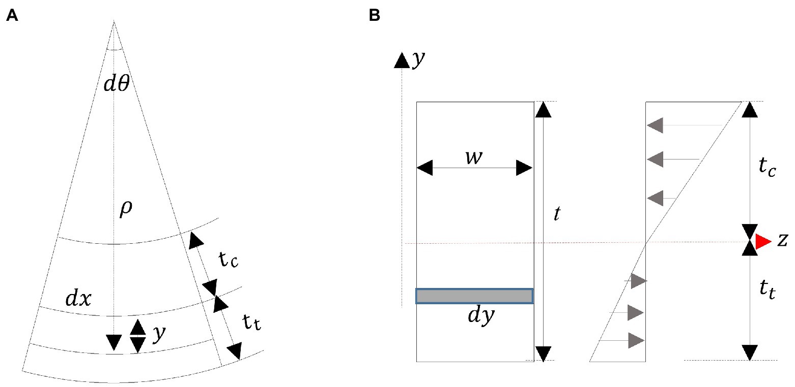
Figure 4. Bending force of rock slab.
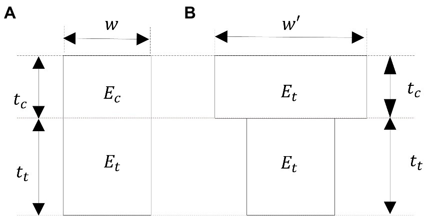
Figure 5. Conversion of the equivalent width.
According to Figures 4, 5, w is beam width, t is beam thickness, A is the area of beam section, tt is tension zone height, and tc is compression zone height. Ec and Et are compression deformation modulus and tensile deformation modulus, respectively. If Ec = Et, the neutral axis position coincides with the symmetry axis of the section, that is, tt = tc. But the tensile modulus and compressive modulus of rock mass are obviously different, that is, Ec ≠ Et, and even if the section has a symmetry axis position, the neutral axis position is inconsistent with the symmetry axis position of the section, that is, tt ≠ tc.
The moment of inertia of the rock slab section can be processed by the equal-generation method, and Et is used instead of Ec, then the width above the neutral axis increases to , which is introduced and called the equivalent width of the section, and , the moment of inertia of the entire section can be expressed as Equation 5, then simplified to Equation 6.
Then, the difference in tensile and compressive characteristics of rock mass is considered, and the toppling bending deflection (TBD) caused by self-weight is estimated by Equation 7. The toppling bending deflection (TBD) caused by the bending moment provided by the self-weight of each rock slab after isopach slabbing is estimated by Equation 8.
3.2. Example analysis
An example was selected to analyze the slabbing effect of toppling deformation based on toppling bending deflection (TBD). The inclination angle of the rock slab α = 60°, γ = 26.0 kN/m3, and t = 5 m, the length of cantilever beam segment l is 10 m, and the compression deformation modulus Ec and the tensile deformation modulus Et are 5 × 10³ MPa and 1 × 10⁴ MPa, respectively. The deformation modulus of slabbing rock mass E is similar to the Ec.
According to Equation 8, the slabbing segment of width m is eliminated, which reflects that the toppling bending deflection (TBD) is independent of the width of rock mass slabbing under self-weight of slabbing rock mass, as the thickness of the slab beam becomes thinner. The TBD is closely related to the thickness of the slab beam.
The slabbing numbers of slab beam thickness were selected as an example (Table 1). The control variable method is supposed to study further the toppling bending deflection (TBD) and the slabbing numbers of slab beam thickness, and the curves of the relationship between the slabbing numbers and the toppling bending deflection (TBD) presented in Figure 6 are concluded. It can be seen from Figure 6 that the toppling bending deflection (TBD) increases remarkably with the number of rock mass slabbing. The change of toppling bending deflection (TBD) is slow when the slabbing number (n) of thickness is <4 and fast when the slabbing number is above 4. The existing research reflects that the toppling bending deflection of thin phyllite is stronger than that of thick massive sand slate (Liu M. et al., 2016; Cai et al., 2019; Zhao et al., 2021).

Table 1. The relationship between the slabbing number and rock slab thickness.
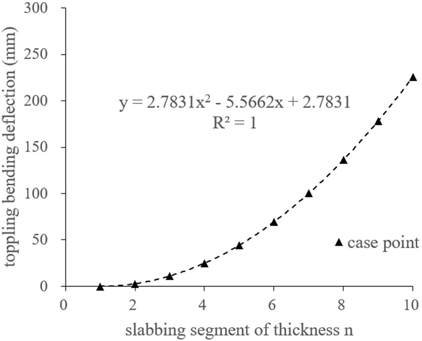
Figure 6. Relationship between the slabbing number and toppling bending deflection.
4. Slabbing effect of toppling failure based on toppling fracture depth
4.1. Three-dimensional mechanical model analysis
A three-dimensional mechanical model was established for a single slab beam, H is the height of the slope, α is the dip angle of the strata (0 < α < 90°), β is the angle of the slope (0 < β < 90°), t is the thickness of the single-layer slab beam, and w is the width of the slab beam. The slab beam is simplified always in a quasi-equilibrium state during the process of bending and toppling and is subjected to self-weight, the friction resistance of the upper and lower adjacent layers, and the lateral constraining force of the left and right sides (Figure 7). The rock layer is homogeneous and uniform in thickness, and the distribution of normal stress and shear stress between layers and lateral joints is linear and only related to the buried depth. In addition, the cohesion and internal frictional angle of the strata are the same, and the lateral joints are also uniform. It is assumed that the parameters of the joint surface are equal to those of the stratum plane. Meanwhile, considering that the joint surface is almost open after unloading, and the cohesion of the joint surface is limited, the influence of the cohesion of the lateral joint surface is not considered in this study. According to the geometric relationship of the model, σi and σi + 1 are the normal stresses of the slab beam, respectively. τi and τi + 1, respectively, are the shear stresses of the slab beam surface, and is the lateral constraint force. W is the self-weight of the slab beam. Therefore, . M is the difference between the bending moment and the resisting moment , is the total bending moment of the slab beam. M can be abbreviated as Equation 9. The deduction process details of Equation 9 are shown in Equations A.1–A.4 in Appendix A.
where is Poisson’s ratio, n is the lateral stress coefficient, and its calculation formula is . The introduced lateral constraint coefficient K presented lateral constraint conditions, which reflected the boundary condition of the slab beam. Supposing K∈[0, 2], 0 means no constraint, which reflects the three-way conditions of the free face; 1 shows a unilateral constraint that reflects the condition on either side of the free face; and 2 signifies three constraints and only one side opening condition. The values of (0, 1) or (1, 2) correspond to different combinations of opening conditions, considering unloading crack conditions (including two free faces, unloading conditions, and one free face). Those values are determined according to the opening and filling degree of unloading cracks. Due to the limited contribution of cohesion after opening, only the friction angle effect is taken into consideration.
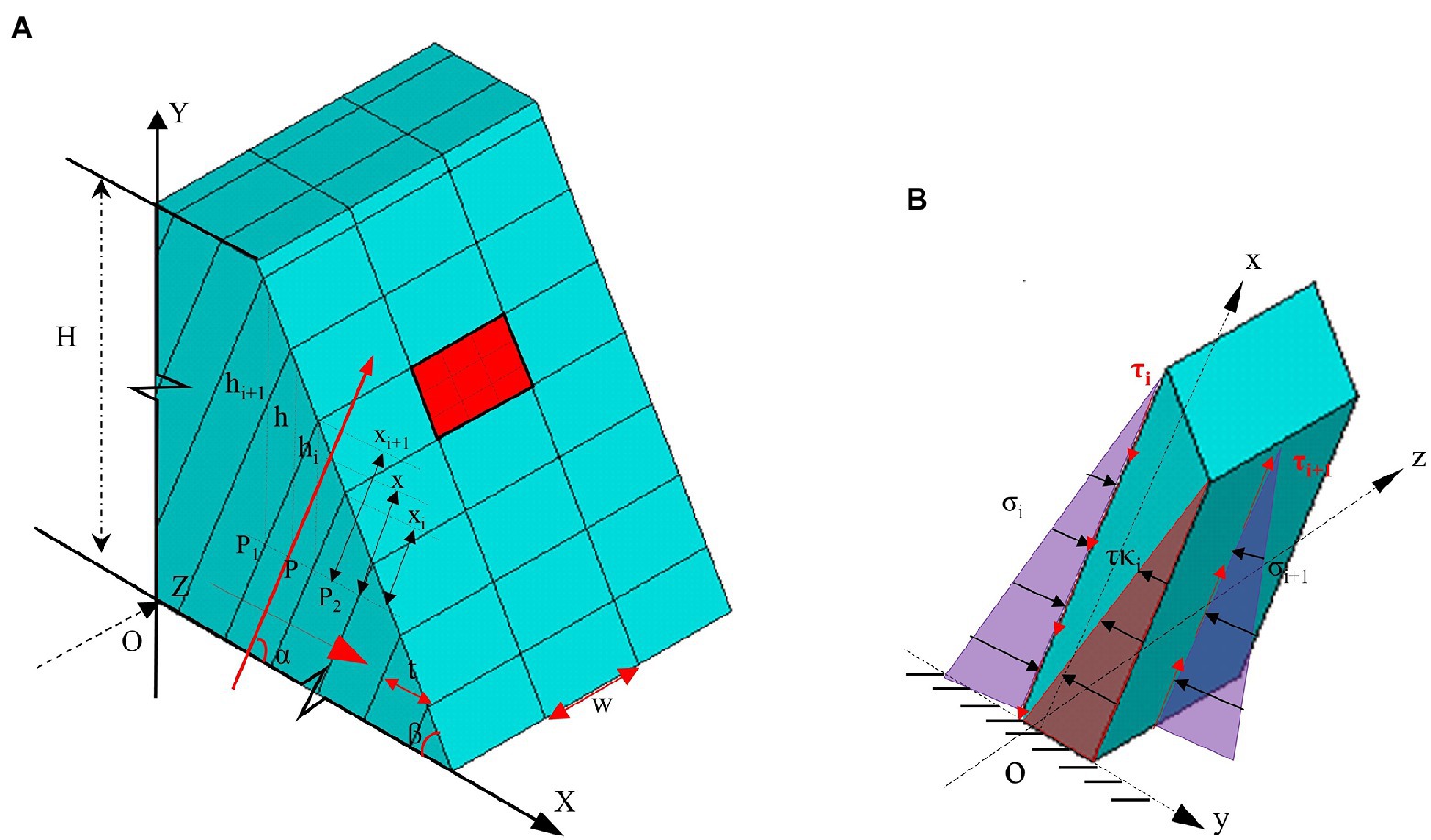
Figure 7. Geometry of the mechanical model. (A) Three-dimensional mechanical model; and (B) a single slab beam.
Since the compressive strength of the rock mass is much higher than its tensile strength, tensile failure is likely to occur. In other words, the condition of toppling failure of the slab beam is M > 0, and . and [] are the tensile stress of the slab beam and the tensile strength of the rock mass, respectively. The tensile stress on the normal section of the beam can be expressed as Equation 10.
where N is the axial force exerted on the slab beam, which is the component force of the self-weight of the slab beam in the x-direction, . A is the normal cross-sectional area of the slab beam, A = tw. y is the distance in the y-direction from the fracture point on the normal section to the centroid of the section, y = t/2. I is the section moment of inertia, I = t3w/12. Equation 10 can be rewritten as Equation 11. A1, B1, C1, D1 are shown in Equation A.5 in Appendix A.
According to Cardin’s formula, if , there must be a real solution of the unary cubic equation, , , . Moreover, the solution is the first toppling fracture depth (TFD) of the slab beam. A0, B0, C0, D0 are shown in Equation A.6 in Appendix A.
According to Cardin’s formula, the first toppling fracture depth x of the slab beam is as follows:
If , Equation 12 is simplified to a unary quadratic equation, namely, , the first toppling fracture depth x of the slab beam is as follows:
It is consistent with the format of the previous two-dimensional mechanical model of the slab beam and will not be described in detail. From equation 12, it can be inferred that the first toppling fracture depth (TFD) of the slab beam is closely related to the slope angle β, rock inclination angle α, the weight of the slab beam γ, thickness t, width w, lateral constraint coefficient n, internal friction angle of the rock layer φ, cohesion of the rock layer c, and lateral constraint factor K. The following example analysis further analyzed the slabbing effect of toppling failure based on toppling fracture depth (TFD).
4.2. Example analysis
The toppling slope of the highway, proposed by Liu H. J. et al. (2016), in the southern mountainous area of Anhui was taken as an example. The slope lithology is composed of metamorphic sand slate, and the inclination angle of the rock layer α = 56°, the slope angle β = 50°, γ = 26.0 kN/m3, Poisson’s ratio = 0.2, t = 0.25 m, the tensile strength = 9,000 kPa, φ = 20°, and c = 50 kPa. The K values of (0, 1) or (1, 2) correspond to different combinations of opening conditions, considering including two free faces or unloading conditions and one free face. This site point is located on the mountain ridge, and there is a gully on one side and an excavation surface of the highway on the other side of the slope. This site point approximately presented two free faces, then w = 2.0 m, and the coefficient of lateral constraint K = 0.01 can be determined according to the geological conditions in the field. According to Equation 12, the TFD of the three-dimensional mechanical model is 14.7 m. The TFD calculated by the two-dimensional mechanical model is 14.0 m, and the toppling development depth measured in the field is ~15.5 m.
The two-dimensional mechanical model with a width of 1.0 m indicates that the lateral joint spacing is the unit width. In most cases, lateral spacing is generally w ≠ 1.0 m, and there is no lateral constraint force caused by the principal stress. Obviously, Equation 12 derived from the three-dimensional mechanical model can be used to accurately calculate the toppling fracture depth (TFD) of the slab beam, and the results are consistent with the depth of the statistical field.
The control variable method is supposed to study further the first toppling fracture depth (TFD) of the slab beam and the related variables. The variables including the thickness t and the width w of the slab beam were mainly selected, and the curves of the relationship between the variables and the first toppling fracture depth (TFD) presented in Figure 8 are concluded.
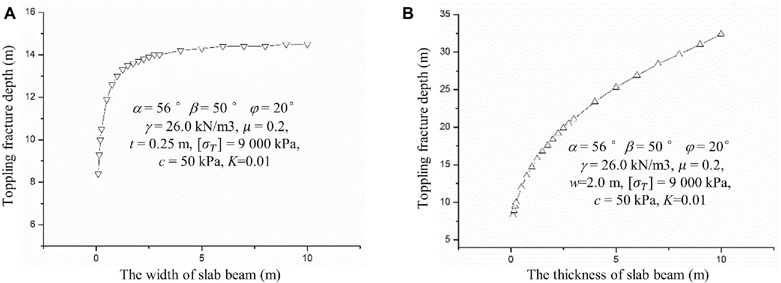
Figure 8. Relationship between toppling fracture depth and width and thickness of the slab beam.
According to the parameter analysis (Figure 8), the toppling fracture depth decreases with the decrease in the width and thickness of the rock slab, and the first toppling fracture depth (TFD) increases inversely with the increase in the width of the slab beam. The first toppling fracture depth (TFD) decreases fast when w < 2.0 m, and it tends to be stable when w is above 2.0 m. The first fracture depth grows relatively fast with the thickness of the decreased slab beam. The smaller the toppling fracture depth (TFD), the more likely the toppling failure will occur.
5. Conclusion
1. There are many factors inducing the rock mass slabbing, which are mainly divided into internal and external factors. The internal factors are the decisive condition, and the external factors play the role of triggering and inducing. The internal factors are mainly the internal texture and structural factors of rock mass, while the external factors are mainly stress differentiation, differential unloading, dynamic load, weathering, artificial activities, etc.
2. Slabbing makes the section size of the rock slab beam narrower and thinner, thus increasing the bending deflection of the toppling failure, indicating that the slabbing of the rock slab aggravates the development of toppling deformation. The toppling bending deflection (TBD) is independent of the width of rock mass slabbing under self-weight, and the toppling bending deflection (TBD) is closely related to the thickness of the slab beam. The change of toppling bending deflection (TBD) is slow when the slab beam slabbing number (n) of thickness is <4 and fast when the slabbing number is above 4.
3. According to the analysis of the three-dimensional mechanical model, the toppling fracture depth (TFD) decreases with the decrease in the width and thickness of the section size of the rock slab. The first toppling fracture depth (TFD) decreases fast when w is <2.0 m, and it tends to be stable when w is above 2.0 m. The first toppling fracture depth (TFD) reduces relatively fast with the thickness t of the decreased slab beam. The smaller the toppling fracture depth (TFD) is, the more likely the toppling failure will occur.
4. The section size of slabbing rock mass is mainly concerned, and the influence of rock mass slabbing on mechanics parameters of rock mass is not considered, especially the amplification effect of the crack tip and the time-varying effect of slabbing rock mass mechanics parameters caused by weathering, which can be regarded as the focus of future research.
Data availability statement
The original contributions presented in the study are included in the article/supplementary material, further inquiries can be directed to the corresponding author.
Author contributions
JC and SL conceived and designed the paper and analyzed the mechanical model. KL and ZW analyzed and interpreted the data. JC wrote the paper. JW, RZ, and ZW revised the paper. All authors contributed to the article and approved the submitted version.
Funding
The study is financially supported by the Opening fund of Key Laboratory of Geological Hazards on Three Gorges Reservoir Area (China Three Gorges University), Ministry of Education (2022KDZ01), the Opening fund of State Key Laboratory of Geohazard Prevention and Geoenvironment Protection (Chengdu University of Technology, SKLGP2022K004), the Opening fund of Key Laboratory of Geohazard Prevention of Hilly Mountains, Ministry of Natural Resources (Fujian Key Laboratory of Geohazard Prevention) (FJKLGH 2022K005) and the National Natural Science Foundation of China (52104082, 41907250, and 41772317). The Opening fund of Key Laboratory of Geological Hazards on Three Gorges Reservoir Area (China Three Gorges University), Ministry of Education (2022KDZ01) will pay for open access publication fees.
Acknowledgments
We appreciate the linguistic assistance provided by AJE during the preparation of this manuscript. Special thanks go to the expert comments from the reviewers and editors for improving the manuscript.
Conflict of interest
KL is employed by Chengdu East Group Co., Ltd. RZ is employed by Shuifa Planning and Design Limited Company.
The remaining authors declare that the research was conducted in the absence of any commercial or financial relationships that could be construed as a potential conflict of interest.
Publisher’s note
All claims expressed in this article are solely those of the authors and do not necessarily represent those of their affiliated organizations, or those of the publisher, the editors and the reviewers. Any product that may be evaluated in this article, or claim that may be made by its manufacturer, is not guaranteed or endorsed by the publisher.
References
Alejano, L. R., Alonso, C. S., Rey, I. P., Arzua, J. R., Alonso, E. S., Gonzalez, J., et al. (2018). Block toppling stability in the case of rock blocks with rounded edges. Eng. Geol. 234, 192–203. doi: 10.1016/j.enggeo.2018.01.010
Amini, M., Majdi, A., and Aydan, Ö. (2009). Stability analysis and the stabilisation of flexural toppling failure. Rock Mech. Rock. Eng. 42, 751–782. doi: 10.1007/s00603-008-0020-2
Amini, M., Majdi, A., and Veshadi, M. A. (2012). Stability analysis of rock slopes against block flexure toppling failure. Rock Mech. Rock. Eng. 45, 519–532. doi: 10.1007/s00603-012-0220-7
Aydan, O., and Kawamoto, T. (1992). The stability of slopes and underground openings against flexural toppling and their stabilization. Rock Mech. Rock. Eng. 25, 143–165. doi: 10.1007/BF01019709
Bao, Y. D., Chen, J. P., Su, L. J., Zhang, W., and Zhan, J. (2022). A novel numerical approach for rock slide blocking river based on the CEFDEM model: a case study from the Samaoding paleolandslide blocking river event. Eng. Geol. 312:106949. doi: 10.1016/j.enggeo.2022.106949
Cai, J. C., Ju, N. P., Huang, R. Q., Zheng, D., Zhao, W. H., Li, L. Q., et al. (2019). Mechanism of toppling and deformation in hard rock slope: a case of bank slope of Hydropower Station, Qinghai Province, China. J. Mt. Sci. 16, 924–934. doi: 10.1007/s11629-018-5096-x
Cai, J. C., Zheng, D., Ju, N. P., Huang, R. Q., and Zhao, W. H. (2022a). Boundary effect of toppling failure based on three-dimensional mechanical model. J. Mt. Sci. 19, 3314–3322. doi: 10.1007/s11629-022-7337-2
Cai, J. C., Zheng, D., Ju, N. P., Wang, J., Zhou, X., and Li, D. (2022b). Time-varying effect of ductile flexural toppling failure on antidip layered rock slope. Front. Earth Sci. 10:943700. doi: 10.3389/feart.2022.943700
Du, K., Tao, M., and Li, X. B. (2016). Experimental study of Slabbing and Rockburst induced by true-Triaxial unloading and local dynamic disturbance. Rock Mech. Rock. Eng. 9, 3437–3453. doi: 10.1007/s00603-016-0990-4
Fujii, Y., Ikeda, N., Onoe, Y., Kanai, Y., Hayakawa, T., Awaji, D., et al. (2022). A case study on severe damage at a tunnel in serpentinite rock mass. SN Appl Sci. 4:34. doi: 10.1007/s42452-021-04924-7
Gong, F. Q., Luo, Y., Li, X. B., Si, X. F., and Tao, M. (2018). Experimental simulation investigation on rockburst induced by spalling failure in deep circular tunnels. Tunn Undergr Sp Tech. 81, 413–427. doi: 10.1016/j.tust.2018.07.035
Gong, F. Q., Wu, W. X., and Li, T. B. (2020). Simulation test of spalling failure of surrounding rock in rectangular tunnels with different height-to-width ratios. Bull. Eng. Geol. Environ. 79, 3207–3219. doi: 10.1007/s10064-020-01734-w
Goodman, R. E. (2013). “Toppling-A fundamental failure mode in discontinuous materials description and analysis,” in 2013 Congress on Stability and Performance of Slopes and Embankments III, Geo-Congress 2013, San Diego, United States. Geotechnical Special Publication, ASCE, 2348–2378.
Goodman, R. E., and Bray, J. W. (1976). “Toppling of rock slopes,” in Rock Engineering for Foundations & Slopes. Boulder, Colorado: ASCE, 201–234.
He, M. C., Sui, Q. R., Li, M. N., Wang, Z., and Tao, Z. (2022). Compensation excavation method control for large deformation disaster of mountain soft rock tunnel. Int. J. Min. Sci. Techno. 32, 951–963. doi: 10.1016/j.ijmst.2022.08.004
Huang, R. Q. (2008). Geodynamic process and stability control of high rock slope development. Chin. J. Rock Mech. Eng. 8, 1525–1544. doi: 10.3321/j.issn:1000-6915.2008.08.002
Huang, R. Q., Li, Y. S., and Yan, M. (2017). The implication and evaluation of toppling failure in engineering geology practice. Chin. J. Eng. Geol. 25, 1165–1181. doi: 10.13544/j.cnki.jeg.2017.05.001
Huang, R. Q., Zhang, Z. Y., and Wang, S. T. (1994). Epigenetic reformation of Rockmass structure. Hydroge. Eng. Geol. 4, 1–6.
Jiang, Q., Zhang, M., Yan, F., Su, G., Feng, X., Xu, D., et al. (2021). Effect of initial minimum principal stress and unloading rate on the spalling and rockburst of marble: a true triaxial experiment investigation. Bull. Eng. Geol. Environ. 80, 1617–1634. doi: 10.1007/s10064-020-01995-5
Li, H. J., He, Y. S., Xu, Q., Deng, J., Li, W., and Wei, Y. (2022b). Detection and segmentation of loess landslides via satellite images: a two-phase framework. Landslides 19, 673–686. doi: 10.1007/s10346-021-01789-0
Li, H. J., He, Y. S., Xu, Q., Deng, J., Li, W., Wei, Y., et al. (2022a). Sematic segmentation of loess landslides with STAPLE mask and fully connected conditional random field. Landslides. doi: 10.1007/s10346-022-01983-8
Liang, X., Tang, S. B., Tang, C. A., Hu, L. H., and Chen, F. (2022). Influence of water on the mechanical properties and failure behaviors of sandstone under Triaxial compression. Rock Mech. Rock. Eng. doi: 10.1007/s00603-022-03121-1
Liu, G. F., Feng, X. T., Jiang, Q., Yao, Z., and Li, S. (2017). In situ observation of spalling process of intact rock mass at large cavern excavation. Eng. Geol. 226, 52–69. doi: 10.1016/j.enggeo.2017.05.012
Liu, M., Liu, F. Z., Huang, R. Q., and Pei, X. J. (2016). Deep-seated large-scale toppling failure in metamorphic rocks: a case study of the Erguxi slope in Southwest China. J. Mt. Sci. 13, 2094–2110. doi: 10.1007/s11629-015-3803-4
Liu, H. J., Zhao, J. J., and Ju, N. P. (2016). Mechanical analysis of toppling failure of rock slope. Rock Soil Mech. 37, 289–294. doi: 10.16285/j.rsm.2016.S1.038
Ni, G. R., and Ye, M. X. (1987). Mechanical analysis of rock mass with the “plate fracture” structure. Yantu Gongcheng Xuebao 9, 99–108.
Nie, W., Wang, W. Q., Tao, Z. G., Zhu, C., and Chen, Y. (2022). Numerical modeling of the NPR-cable and its applications for analysis of a slide-toe-toppling failure. Comput. Geotech. 149:104852. doi: 10.1016/j.compgeo.2022.104852
Pan, P. Z., Miao, S. T., Wu, Z. H., Feng, X. T., and Shao, C. (2020). Laboratory observation of Spalling process induced by tangential stress concentration in hard rock tunnel. Int. J. Geomech. 20:4020011. doi: 10.1061/(ASCE)GM.1943-5622.0001620
Qin, C. A., Chen, G. Q., Zhu, J., and Tang, P. (2020). A precursor of bedding rockslide: rock spalling in the key block triggered by tensile cracks. Bull. Eng. Geol. Environ. 79, 2513–2528. doi: 10.1007/s10064-019-01703-y
Qiu, S. L., Feng, X. T., Zhang, C. Q., and Xiang, T. (2014). Estimation of rockburst wall-rock velocity invoked by slab flexure sources in deep tunnels. Can. Geotech. J. 51, 520–539. doi: 10.1139/cgj-2013-0337
Sun, Z. H., Hou, Z. S., and Zhang, A. P. (2012). Research on tensile Slabbing failure of marble at Jinping II Hydropower Station. J. Water Resour. Archit. Eng. 10, 24–27. doi: 10.3969/j.issn.1672-1144.2012.01.008
Sun, G. Z., and Zhang, W. B. (1985). A common rock structure-board crack structure and its mechanical model. J. Eng. Geol. 28, 275–282.
Tang, S. B., Li, J. M., Ding, S., and Zhang, L. (2022). The influence of water-stress loading sequences on the creep behaviour of granite. B Eng. Geol. Environ. 81:482. doi: 10.1007/s10064-022-02987-3
Tao, L. J., Chang, C., Huang, R. Q., Chai, H. J., and Li, P. F. (2000). Epigenetic reformation of the Rockmass structure in a deep downcutting gorge. J. Chengdu Univ. Technol. 27, 383–387. doi: 10.3969/j.issn.1671-9727.2000.04.010
Tao, Z. G., Geng, Q., Zhu, C., He, M., Cai, H., Pang, S., et al. (2019). The mechanical mechanism of large-scale toppling failure for counter-inclined rock slopes. J. Geophys. Eng. 16, 541–558. doi: 10.1093/jge/gxz020
Wang, Y., Zhu, C., He, M. C., Wang, X., and le, H. (2022). Macro-meso dynamic fracture behaviors of Xinjiang marble exposed to freeze thaw and frequent impact disturbance loads: a lab-scale testing. Geomech. Geophys. Geo. 8:154. doi: 10.1007/s40948-022-00472-5
Wu, S. Y., Gong, Q. M., Wang, G., Hou, Z. S., and She, Q. R. (2010). Experimental study slabbing failure for deep-buried marble at Jinping II Hydropower Station and its influences on TBM excavation. Chin. J. Rock Mech. Eng. 29, 1089–1095.
Xu, Y. X., Wang, G. F., Li, M. Z., Xu, Y. J., Zhou, C. T., and Zhang, J. H. (2021). Mechanism of slabbed spalling failure of the coal face in fully mechanized caving face with super large cutting height. J. Min. Saf. Eng. 38, 19–30. doi: 10.13545/j.cnki.jmse.2019.0416
Zhao, W. H., Zhang, C. Q., and Ju, N. P. (2021). Identification and zonation of deep-seated toppling deformation in a metamorphic rock slope. Bull. Eng. Geol. Environ. 80, 1981–1997. doi: 10.1007/s10064-020-02027-y
Zheng, Y., Chen, C. X., Liu, T. T., Zhang, H., Xia, K., and Liu, F. (2018). Study on the mechanisms of flexural toppling failure in anti-inclined rock slopes using numerical and limit equilibrium models. Eng. Geol. 237, 116–128. doi: 10.1016/j.enggeo.2018.02.006
Zhou, H., Lu, J. J., Xu, R. C., Zhang, C. Q., and Meng, F. Z. (2015). Critical problems of study of slabbing failure of surrounding rock in deep hard rock tunnel and research progress. Rock Soil Mech. 36, 2737–2749. doi: 10.16285/j.rsm.2015.10.001
Zhou, Y., Sun, Z., Wang, L., Wang, Y., and Ding, Y. P. (2018). Meso research on mechanical properties and slab failure mechanism of pre-fractured rock mass under the condition of one side restriction loading. Rock Soil Mech. 39, 4385–4394. doi: 10.16285/j.rsm.2017.2597
Zhu, C., Xu, Y. Z., Wu, Y. X., He, M., Zhu, C., Meng, Q., et al. (2022). A hybrid artificial bee colony algorithm and support vector machine for predicting blast-induced ground vibration. Earthq. Eng. Eng. Vib. 21, 861–876. doi: 10.1007/s11803-022-2125-0
Appendix A
Figure 7 presents the mechanical model under the global coordinate system.
Because , the stress state at a point in the slab beam is as follows:
where n is the lateral stress coefficient and its calculation formula is as follows:
where is Poisson’s ratio.
Because the toppling is still in the quasi-static equilibrium of dislocation each other and meets > , the rock slab can slide along with the plane of the rock layer. Thus, = , the stress state at P1 and P2 can be rewritten as follows:
Similarly, the lateral constraint force of the lateral section can be expressed as .
Keywords: rock mass slabbing, toppling failure, mechanical model, mechanism of slabbing, TFD
Citation: Cai J, Lu S, Li K, Wu Z, Zhao R and Wang J (2023) Mechanical mechanism of rock mass slabbing aggravating toppling failure. Front. Ecol. Evol. 10:1103249. doi: 10.3389/fevo.2022.1103249
Edited by:
Yunhui Zhang, Southwest Jiaotong University, ChinaReviewed by:
Huajin Li, Chengdu University, ChinaHua Li, Sichuan University, China
Peng Tang, Jiangxi University of Science and Technology, China
Chun Zhu, Hohai University, China
Copyright © 2023 Cai, Lu, Li, Wu, Zhao and Wang. This is an open-access article distributed under the terms of the Creative Commons Attribution License (CC BY). The use, distribution or reproduction in other forums is permitted, provided the original author(s) and the copyright owner(s) are credited and that the original publication in this journal is cited, in accordance with accepted academic practice. No use, distribution or reproduction is permitted which does not comply with these terms.
*Correspondence: Shuqiang Lu, ✉ Lsq2197@163.com