SmartORC: smart orchestration of resources in the compute continuum
 Emanuele Carlini1†
  Massimo Coppola1†
  Patrizio Dazzi2*†
  Luca Ferrucci2† Hanna Kavalionak1† Ioannis Korontanis3†
  Matteo Mordacchini4†
  Konstantinos Tserpes3†
- 1Institute of Information Science and Technologies “A. Faedo”, National Research Council of Italy, Pisa, Italy
- 2Department of Computer Science, University of Pisa, Pisa, Italy
- 3Department of Informatics and Telematics, Harokopio University of Athens, Kallithea, Greece
- 4Institute of Informatics and Telematics, National Research Council of Italy, Pisa, Italy
The promise of the compute continuum is to present applications with a flexible and transparent view of the resources in the Internet of Things–Edge–Cloud ecosystem. However, such a promise requires tackling complex challenges to maximize the benefits of both the cloud and the edge. Challenges include managing a highly distributed platform, matching services and resources, harnessing resource heterogeneity, and adapting the deployment of services to the changes in resources and applications. In this study, we present SmartORC, a comprehensive set of components designed to provide a complete framework for managing resources and applications in the Compute Continuum. Along with the description of all the SmartORC subcomponents, we have also provided the results of an evaluation aimed at showcasing the framework's capability.
1. Introduction
The proliferation of mobile devices and the growth of mobile networks have led to a significant increase in the demand for edge computing applications (Korontanis et al., 2020). These applications require processing to be performed closer to the data source and end users, which has led to the emergence of the compute continuum. The compute continuum is a distributed computing ecosystem that encompasses a wide range of heterogeneous computational and network resources, ranging from large supercomputers and high-performance computing clusters to smaller, localized edge devices.
The compute continuum presents many challenges, including the need for efficient resource discovery, monitoring, and management, as well as the need to coordinate the execution of applications across a diverse range of resources and environments. To address these challenges, orchestration plays a critical role in managing and coordinating the execution of applications in the compute continuum (Youn et al., 2017).
Efficient orchestration requires both proactive and reactive processes to support the application's runtime and adapt its deployment according to changes in the application workload and resource availability. Proactive processes involve predicting future resource demands and making appropriate allocation decisions in advance, while reactive processes involve responding to changes in resource availability and workload, such as scaling up or down resources or migrating applications to different devices.
To support efficient orchestration in the compute continuum, we present SMARTORC, a comprehensive orchestrator designed to manage different computational resources and provide allocation plans for deploying applications. The SMARTORC architecture is highly modular and based on several core macro services, including application description and manipulation, resource discovery and monitoring, matchmaking solver, user management, and object storage. These services work together to support the orchestration of applications in the compute continuum.
In addition to its modular architecture, SMARTORC supports hierarchical and distributed orchestration approaches, which are essential for managing the compute continuum. Hierarchical orchestration involves organizing devices into groups or clusters based on their capabilities and location, enabling efficient management of resources and delegation of responsibilities. This approach allows for the creation of a hierarchical structure in which each group is responsible for managing a subset of devices. The hierarchical structure allows for the efficient management of resources and enables the delegation of responsibilities to lower levels of the hierarchy, thus reducing the complexity and workload of higher levels.
Distributed orchestration involves distributing orchestration tasks across the compute continuum, enabling each device to act as an orchestrator and contribute to the orchestration process. This approach offers several benefits, including increased fault tolerance, reduced latency, and improved scalability. By distributing orchestration tasks across the compute continuum, SMARTORC can take advantage of the resources available on each device, making it easier to manage a large number of devices.
Combining hierarchical and distributed orchestration approaches provides a powerful solution for managing the compute continuum. By organizing devices into hierarchical clusters and distributing orchestration tasks across the clusters, SMARTORC can efficiently manage a large number of devices while ensuring scalability, fault tolerance, and low latency. This approach is particularly useful in environments where devices have varying capabilities and connectivity, making it difficult to manage them using traditional centralized orchestration approaches.
To support hierarchical and distributed orchestration, SMARTORC's architecture is designed to be highly modular and scalable. The core macro services of SMARTORC are designed to be distributed and can be deployed on different devices in the compute continuum. This design enables orchestration tasks to be distributed across devices and clusters while ensuring efficient communication and coordination between the different components of the system.
The article is organized as follows: Section 2 sheds light on the scientific literature that relates to this topic and motivates this research. Section 3 introduces the optimization model for deploying application components in SMARTORC considering their QoS requirements and resource constraints. Section 4 discusses the architecture of SMARTORC from both a conceptual perspective and a system viewpoint in which the design of all the subsystems is discussed in full detail. Section 5 provides information about the current prototype of SMARTORC, which is currently used in two European Research projects. This section also provides information about the hierarchical version of the tool along with the description of the fully decentralized version, currently in development. Section 6 presents some figures on the performance achieved by both the current prototype and the one under development (representing the next release of SMARTORC, which focuses on application placement using highly decentralized approaches). Finally, Section 7 concludes the paper by summarizing the actual extent of its contribution and outlining future research activities related to and allowed by SMARTORC.
2. Background
Orchestration is the automated management and coordination of applications and services. Our present study focuses on the orchestration of applications, where the services and components of each application are mapped for deployment and to be dynamically managed on infrastructure resources. Orchestration is applied to the basic units of execution that support applications. As continuum platforms become increasingly exploited, application components are progressively shrinking from Virtual Machines (VMs) to containers down to Unikernel (Madhavapeddy et al., 2013) instances and serverless functions. Our target, the compute continuum, poses several additional challenges to orchestration (Vaquero et al., 2019) when compared with those already impacting cloud orchestration (Cascella et al., 2013; Casalicchio, 2017).
The heterogeneity and scale of the problem are just the most striking issues to be tackled. Heterogeneity is typically higher toward the edge of the continuum, populated by resources that vary in their hardware capabilities, access methods, and protocols and possibly belong to distinct administrative domains. The scale of the continuum also poses a significant challenge: composed of a higher and higher number of resources. This makes it difficult for the orchestrator to make optimal decisions. Among the techniques reviewed by Vaquero et al. (2019), those in the class of eventually consistent/probabilistic orchestration methods iteratively improve the initial solution found, which is likely to be suboptimal. The initial deployment is improved after refining its evaluation, and the migration/redeployment of parts of the application can happen based on updated information. Late calibration (Wen et al., 2017) is one such technique. Many current orchestration frameworks employ similar incremental techniques to take the system closer to the desired state progressively. The base idea for these techniques, asymptotic configuration, dates back to 1998 (Pollock et al., 1998).
Several orchestration solutions in the literature work offline and need complete knowledge of the set of potential applications and computing nodes, i.e., a scenario with stronger assumptions than the dynamic edge/cloud continuum can uphold. One study that approaches these simpler settings is Maia et al. (2019). They explore two different methods to develop an orchestration; the first one based on genetic algorithms and the second one based on employing a mixed-integer linear programming (MILP) heuristic.
To improve the scalability of the platform, several research studies attempted to optimize the overall performance of a system by limiting the communications with centralized clouds (Altmann et al., 2017; Salaht et al., 2020; Ahmed et al., 2022). The rationale is that data exchanges between cloud and edge systems introduce significant overheads and can degrade the performance of those applications running on the edge systems that need strong locality and rely on context-based services.
A well-known approach to overcome the scalability limit due to centralized management is the adoption of decentralized and/or self-organizing solutions (Toffetti et al., 2015; Carlini et al., 2016; Mordacchini et al., 2020). These solutions achieve their goal by moving the orchestration logic closer to users and data (Maia et al., 2019; Dazzi and Mordacchini, 2020; Ning et al., 2020). In decentralized orchestration approaches, many independent entities, each one controlling a set of resources, recognize resources based on predefined ontologies and execute deployment requests by negotiating among themselves (Sim, 2012). Even though distributed orchestration was proposed more than 15 years ago (Chafle et al., 2004), the technique was not immediately successful. Beraldi et al. (2017) propose CooLoad, a scheme in which edge data centers redirect their requests to other adjacent data centers whenever they become congested. Carlini et al. (2016) propose a decentralized system in which autonomous entities in a Cloud Federation communicate to exchange computational services, attempting to maximize the profit of the whole Federation. The viewpoint of our study is closer to solutions that aim at placing the applications close to the data they access or moving the application services close to their users. An example is given by Ning et al. (2020). They propose an online and distributed solution for service placement at the edge based on a probabilistic optimization method. Their approach computes the utility of service migration and placement. This evaluation is done by considering the cost, storage capability, and latency of service migration to determine the optimal service placement configurations. Several of the distributed orchestration solutions target specific subroblems. Aral and Ovatman (2018) is an example of the distributed strategies that can be applied for data placement and replication at the edge. The aim of our study differs from these solutions, as we are concerned with computing requests and the related optimal placement and selection of service instances at the edge.
Recently, research started about applying machine learning (ML) techniques to different orchestration-related tasks. As it is difficult to find enough quality data of general significance and train a model complex enough to cover all orchestration activities, current research is experimenting with the combination of simpler models (Talagala et al., 2018).
In the next section, we have addressed the optimization problem that we have solved to deploy next-gen applications on the heterogeneous and sparse pool of resources typical of the compute continuum, by giving a high-level linear programming model. Such a model aims to orchestrate different kinds of services and devices, including, for example, Internet of Things (IoT) devices such as sensors or actuators for smart homes and cities, or storage, either as a device features or as permanent services that the application needs to access.
The SMARTORC architecture is designed to easily implement and plug-in different orchestration strategies and optimization techniques. In our current prototype, an MILP solver plug-in was exploited to solve the optimization problem in an exact way, implementing a centralized solution based on a unique instance of SMARTORC: such an instance has complete knowledge about the availability of resources and placement of all deployed applications. We plan to exploit decentralized, approximated techniques and algorithms based on distributed/local knowledge in the next prototype, which will fully exploit the architecture we present in this study. By sacrificing optimality for computational efficiency, approximated algorithms enable the deployment and orchestration of applications in large-scale and geographically distributed systems such as the compute continuum. In the studies of Ferrucci et al. (2020) and Mordacchini et al. (2021), self-organizing distributed algorithms were developed and tested. The behavior of those methods is relevant as they can be applied within SMARTORC and is discussed in Section 6.2. The efficient exploitation of the resources of the compute continuum is obtained while also optimizing the energy consumption of the system as a whole by exploiting point-to-point interactions between edge entities, known as edge mini-clouds (EMs). As we discussed later in the article, the combination of local sensing and distributed information exchange allows for improving the execution cost parameters (e.g., energy, number of active resources) while respecting the boundaries set forth by application quality-of-service (QoS) constraints.
3. Optimization problem definition and modelization
In the context of this article, where the IoT–edge–loud ecosystem is taken into consideration, we consider a system as being made of multiple entities, either EMs or central clouds (CCs). Both of these entity types are aggregations of heterogeneous resources, but they differ in other main features such as size and resource granularity. CCs, usually, have a great abundance of computing, memory, and storage resources, which are centralized and placed in geographically distant data centers. The elasticity property of CC sites gives users the illusion of ideal availability, enjoying an “infinite” quantity of resources. However, solely relying on running application components within CCs can negatively impact some important features of modern applications. Increasing latency and hindered scalability when the size of the infrastructure increases are critical issues for, e.g., data streaming applications and Augmented Reality/Virtual Reality (AR/VR) ones.
Edge computing is an attempt to overcome these limitations. It is a service computing paradigm that aims at bringing the computation as close as possible to the data producers and/or consumers (e.g., end users). This can be achieved by placing applications and application components on a potentially large number of edge resources that are geographically distributed and uniformly scattered over a broad area. An EM is a set of such resources, often very constrained in their features, sometimes power-constrained, with a common tenancy and geographically located in a certain area. EMs may be internally heterogeneous and usually are heterogeneous with respect to each other.
In this section, we provide an MILP model for the optimization problem of deploying a set of components of a given application onto the available resources of a set of data centers containing a mixture of EMs and CCs.
In our model, an application A is represented by an undirected graph GA = < C, E >, where C represents a set of N vertices and E represents the set of M edges connecting the vertices. Each vertex ci ∈ C with i ∈ {1, …, N} embodies a single component of the application that offers a distinct service for the application, following the microservice paradigm. Different applications can be deployed on distinct EMs or CCs based on the application's QoS requirements.
Each edge ei, j ∈ E represents an undirected communication path connecting application components vi and vj, with i, j ∈ {1, …, N}:i ≠ j.
Every vertex (an application component) and every edge (a communication link) can be labeled with a set of QoS attributes or requirements Q = {q1, …, qS} that are associated with it and can be classified in two categories, similar to what is defined in the study by Ye et al. (2011):
• ascending/descending QoS attributes, where either higher or lower values of the attribute are better for the application performance;
• equal QoS attributes, in which only equality or inequality is meaningful.
Examples of ascending/descending QoS attributes are the minimum number of Central Processing Unit (CPU) cores, and the quantity of memory or disk space, while examples of equal QoS attributes are the presence/absence of a particular software feature, e.g., an operating system (OS) or a software license, or the availability of a hardware feature, e.g, a graphic processing unit (GPU). Previous examples of QoS requirements are in the class of so-called intra requirements since they are associated with a single vertex or application component and are modeled as constraints over the resources of a single data center (EM or CC). Conversely, maximum latency or minimum bandwidth are examples of inter QoS attributes as they are associated with an edge. The inter attributes are modeled as constraints over a set of resources belonging to different vertices (i.e., possibly located in distinct data centers after the orchestration is done).
Some requirements imply the allocation of resources that cannot be shared. We call numerical a metric requirement that refers to a resource that cannot be shared between different components or communication channels. The required value reduces the available amount of the resource, as is the case for the number of (exclusive) cores, the amount of disk space, or the consumed bandwidth of a channel over a link. An example of a QoS requirement that is non-numerical (or can be assumed to be in ordinary working conditions) is the maximum latency induced by a communication channel.
As part of our modelization effort, we need to model the available portion of the compute continuum, which we do following the approach detailed earlier. The compute continuum is represented as an undirected graph GCont = < D, L >, where D represents a set of P vertexes and L represents the set of V edges connecting the vertices. Each vertex di ∈ D, with i ∈ {1, …, P} representing a single data center (an EM or CC) of the continuum. The resources associated with each data center are the sum of all the resources available among the devices, servers, and other commodities that the data center supervises. Each edge li, j ∈ L represents an undirected communication link between two different data centers labeled as di and dj, with i, j ∈ P:i ≠ j.
As it is for applications, each data center Dd and each communication link Lv is associated with a limited amount of intra-data center (intra) and inter-data center (inter) resources R = {r1, …, rT}, i.e., the maximum number of CPU nodes, memory size, or disk space or the minimum latency and the maximum bandwidth over links.
A first set of constraints in the model comes from the fact that the application components in execution at any point in time cannot exceed the currently available capacity of such resources, indicated as Cri, j, where ri ∈ R and j ∈ {1, …, M} for intra resources but j ∈ {1, …, V} for inter resources. 1
For every type of QoS requirement qi ∈ Q, there is a corresponding resource ri ∈ R against which the requirement has to be satisfied. When attributes are used in specifying the application, they define constraint values to be respected by the corresponding resource allocated within the compute continuum. For instance, the QoS requirement of a component about the number of cores needed to reach an expected performance level must be satisfied by the number of cores of the data center di on which it will be deployed. Requirements over edges are analogous, that is, e.g., the maximum latency stipulated by a communication channel between two different components must be satisfied by the minimum latency associated to the communication link li ∈ GCont connecting the two data centers di and dj, where the two components are deployed. An inter constraint on networking is assumed to be trivial, and we ignore it if i = j, i.e., if the components are deployed on the same data center di.
To express our constraints, we employed a set of auxiliary functions characterizing the set of QoS requirements. The first such function will be used to distinguish between intra and inter QoS requirements:
A second characterization function will be used to distinguish between ascending/descending QoS requirements and strictly equal QoS requirements:
Finally, we have to take into consideration numerical QoS requirements, which imply using up a measurable quantity of an available resource. It is worth noting that numerical requirements in our modelization can be ascending or descending but not of the equal type. For this purpose, we introduce the last characterization function, qualifying numerical vs. non-numerical QoS requirements:
In defining our MILP model, we did not include constraints on the order of the deployment of different components of the Application A. Hence, our model solution does not cover the scheduling of application components but only the needed resource orchestration.
Using the notation introduced in this section, we have the following optimization problem:
In the preceding definition, we introduced a set of integer binary decision variables xi, j. Each one represents whether the component ci, i ∈ {1, …, P} of application A has been deployed on the data center dj, j ∈ {1, …, M}:
Our problem has 12 groups of constraints. The constraints of group (1) force each valid solution to unequivocally deploy each component of the application A on exactly one datacenter. Constraints in groups (2), (3), and (4) ensure that any component allocation shall not exceed the resource limits of the data center on which it will be deployed; they differ in the type of QoS and resources they model. In constraint group (2), we deal with numerical (ascending or descending) requirements: the characterization functions fnum and finter are applied to each QoS requirements and multiplied with each other such that the contraint is ignored when the result is zero, since, in this case, it is always satisfied independently from the value assigned to the decision variable. Constraints in group (3) handle non-numerical (ascending or descending) requirements, while constraints in group (4) apply to non-numerical requirements of the equal kind (i.e., the presence of a certain OS or graphics card, codifying a specific card model or OS with a unique integer value).
Constraints on requirements and resources defined over communication links are encoded by equation groups (8), (9), and (10) that, in a similar way to constraint groups (2), (3), and (4), model, respectively, numerical (i.e., bandwidth), ascending/descending (i.e., latency), and equal requirements. We need to check the requirement over a certain communication channel between two different components i1 and i2 of application A iff these components are deployed on different data centers d1 and d2 and a network link exists between d1 and d2.
Some constraints of our model result from applying standard techniques to turn the initial formulation into one suitable for MILP optimization. In the straightforward modelization of the optimization problem, which we have not shown here, each inter requirement is modeled by multiplying the two decision variables xi1, d1xi2, d2 iff a network link exists between d1 and d2. However, this approach leads to a non-linear programming problem. We linearize such constraints by introducing a new set of auxiliary binary decision variables yi1, d1, i2, d2 such that yi1, d1, i2, d2 = xi1, d1xi2, d2, ∀i1, i2 ∈ {1, …, N} and d1, d2 ∈ {1, …, P}:i1≠i2 and d1≠d2.
To restrict the new problem to the same set of solutions of the first modelization, we also need to introduce the new sets of constraint, (5), (6), and (7). The constraints in groups (6) and (7) ensure that yi1, d1, i2, d2 = 0 if xi1, d1 = 0 or xi2, d2 = 0. However, the constraints in group (5) ensure that yi1, d1, i2, d2 = 1 iff xi1, d1 = 1 and xi2, d2 = 1.
Constraint groups (11) and (12) restrict Boolean values to our decision variables x and auxiliary variables y. Descending numerical or non-numerical requirements are modeled by changing the sign of both the requirement and the corresponding resource; i.e., the latency requirement is an ascending non-numerical requirement of the type qlat ≥ Crlat, l, which could be transformed in the constraint −qlat ≤ −Crlat, l., omitting the rest of the groups.
The objective function is indicated as a general utility function over the two vectors of the decision variables of the optimization problem, x and y. Such a utility function represents a utility value specified by the owner of the application and embeds the policy metrics that need to be optimized in the specific orchestration problem. In our first prototype, we use the following objective function:
This function attempts to maximize the availability of the numerical inter resources of all the data centers. It is also possible to apply more complicated functions or add a resource cost model.
It is possible to prove that the optimization problem described in group (1) is NP-hard by observing that it contains the minimization version of the generalized assignment problem (Min-GAP), described by Ross and Soland (1975), Nauss (2003), Kundakcioglu and Alizamir (2009), as a particular case.
4. SmartORC architecture
This section presents the architecture of SMARTORC adopting an incremental approach. Section 4.1 presents the main design objectives of SMARTORC along with a brief description of its main modules. Conversely, Section 4.2 discusses the architecture of SMARTORC with full details by adopting the Archimate specification.
4.1. Conceptual architecture
The objective of SMARTORC is to provide a complete orchestration framework to manage EM and CC resources, enacting the hosting of applications into the set of resources belonging to the continuum.
The main challenge, the one that we plan to address, is to match application QoS requirements and users' quality-of-experience (QoE) constraints while achieving efficient exploitation of resources. SMARTORC development began within the ACCORDION H2020 project (Korontanis et al., 2020) with the explicit goal of dealing with both QoS and QoE constraints. The definition of QoE depends, however, on many factors, including the actual kind of application and the type of user interface. As a very informal example, the QoE in interactive simulations is often subject to constraints on server-to-client latency, as well as on desynchronization among separate users, while QoE for immersive three-dimensional VR/AR simulations is much more strongly linked to the round-trip latency between the physical user and the simulated environment presented by the immersive device.
QoE targets are often defined indirectly via user surveys and studies and are generally linked to QoS constraints in non-trivial ways. For example, interactive services such as mobile games, in which no video is streamed over the network, are most prone to network depredations, including delay, packet loss, and jitter. A proper prediction of these values, and the consequent QoE-aware orchestration, is still an ongoing challenge (Schmidt et al., 2021). Since a complete QoE discussion would bring us far from the article's focus on orchestration, we have restricted the following discussion to QoS parameters on the tacit assumption that an analytic model of the expected QoE for an application can be assessed starting from QoS parameters, those that the orchestration can control. We have discussed the following examples of QoS constraints and strategies to match them without wasting resources.
Such potentially conflicting objectives are particularly complex in a highly dynamic, distributed, and heterogeneous continuum of edge and cloud devices. To be properly instrumented to manage such complexity, SMARTORC is a resource orchestration framework whose main functionalities are
• to allow the allocation of resources to various types of applications, taking into account both the associated QoS requirements and the structural topologies;
• to define a deployment plan for all the components of an application; and
• to amend (or compose a brand-new) deployment plan when one or more application requirements are violated, while attempting to minimize the number and cost of the changes;
SMARTORC is organized into five distinct modules, as depicted in Figure 1, presenting the conceptual architecture of our proposed framework. These modules are briefly presented in the current section and illustrated more in detail in Section 4.2:
• Resource discovery, indexing, and monitoring: This module aims to collect, index, and keep all the relevant information about the resources managed by a specific instance of SMARTORC. The main challenge is to provide such information in a scalable way while guaranteeing the value of the information provided.
• The SMARTORC solver: This is the core module of SMARTORC. It is aimed at solving the matchmaking problem between the available resources and the functional and non-functional requirements of a given application; in particular, the focus is on the QoS requirements of the application. The main challenge is to provide this result in a scalable way while preserving high-quality results in terms of cost/benefit trade-off.
• Application description and manipulation: This module's goal is to manipulate and translate the native description of the applications along with their topology and requirements. SMARTORC exploits an internal representation. The main challenge in designing such a representation is to provide enough flexibility while keeping the semantics of the application and its requirements during the translation process.
• User management: This module provides registration and authorization mechanisms for end users and administrators. In particular, administrators could perform tasks such as manipulating the set of end-users, adding or removing edge data centers and resources, or performing system configuration.
• Object store: This module is aimed to store dynamic or static data about users, the status of applications, and the (almost) real-time availability of resources collected by monitoring applications on EMs and CCs.
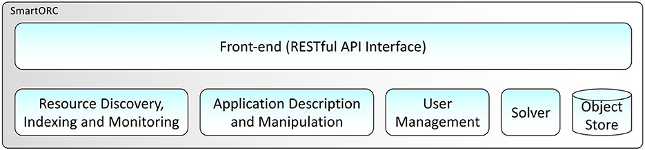
Figure 1. SMARTORC conceptual architecture Application Programming Interface (API).
4.2. System architecture
The SMARTORC2 architecture has been designed and formatted using the Archimate standard (TheOpenGroupStandard, 2019). The diagrams presented in this subsection comply with the Archimate Core Language specification v.3.1. As previously mentioned in Section 4.1, from a conceptual architecture perspective SMARTORC encompasses five subsystems. This section describes them, with each subsection providing details concerning the actual design of one subsystem. Section 4.2.3 also provides examples about the Topology and Orchestration Specification for Cloud Applications (TOSCA) format that we use to describe applications' QoS and deployment constraints.
4.2.1. Resource discovery, indexing, and monitoring
The Resource discovery, indexing, and monitoring subsystem (RID) is a critical component that supports SMARTORC in its process of finding the best resources for an application, given a set of QoS and QoE requirements, and is aimed at providing the Solver subsystem with up-to-date information about computational resources that can be used for hosting application instances. The challenge is to provide such information in a scalable and precise way, a well-known problem in the scientific literature (Albrecht et al., 2008; Zarrin et al., 2018). Figure 2 depicts the breakdown of the RID structure. The design is quite articulated and embeds two interfaces, one for the management of infrastructure resources (Resource Management) and one for gaining access to the available resources (Resource Listing).
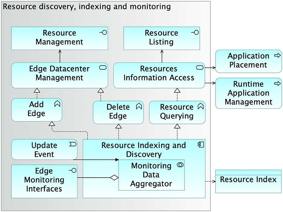
Figure 2. Architecture of the module performing resource discovery, indexing, and monitoring.
The Resource Management interface is used and accessed by SMARTORC administrators and is provided by the Edge Datacenter Management service. Such a service is an active entity responsible for providing the mechanisms for adding (Add Edge) or removing (Delete Edge) edge data centers to the set of resources that SMARTORC can consider in the application placement process. The Resource Listing interface is instead dedicated to SMARTORC end users. It is the access point to the Resources Information Access (RIA) service, which is the entity enabling providing information about the resources from the edge data centers that SMARTORC can exploit to host applications. The RIA provides mechanisms for resource querying that are used by the Application Placement and Runtime Application Management processes.
Both the Edge Datacenter Management and the Resources Information Access services are implemented by the Resource Indexing and Discovery module. The Resource Indexing and Discovery is the entity in charge of providing most of the business logic of the entire subsystem. It keeps an up-to-date index of the resources stored in the SMARTORC Object Store. It collects monitoring information from the many different interfaces provided by the edge data centers indexed by SMARTORC, employing the embedded Monitoring Data Aggregator module. The module behaves both as an aggregator and as a homogenization and abstraction layer toward the (potentially different) monitoring mechanisms offered by the edge data centres. Resource information is periodically refreshed, but a “forced” update can also be triggered by custom policies defined by SMARTORC administrators. A detailed discussion of the technologies that ensure secure, scalable, and reliable data management is beyond this article's objective.
4.2.2. The SmartORC solver
The core of SMARTORC is represented by the Solver subsystem, conducting the matchmaking activities for finding the best resources for a given application, depending on QoE and QoS requirements. This is a well-known and largely studied NP-hard problem (Cattrysse and Van Wassenhove, 1992). Figure 3 presents the system architecture of the SMARTORC Solver subsystem. Its functionalities are provided through the Application Mapping and Re-mapping service. The service is used by two main SMARTORC processes: Application Placement and Runtime Application Management. The mechanisms provided by this service are the ones needed to Compute Mapping and the ones needed to Adapt Mapping that is already computed, which are amended without triggering a complete remapping. The software module encapsulating the business logic for determining the best mapping plans is Mapping Planner, designed to be flexible enough to exploit different solutions and algorithms for selecting the best matchmaking between resources and applications.
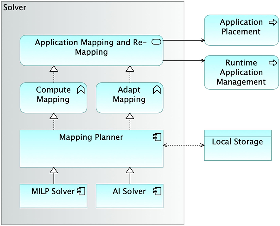
Figure 3. Architecture of the solver module, performing the actual orchestration according to the selected optimization plugin. MILP, mixed-integer linear program; AI, artificial intelligence.
The current design of SMARTORC allows to leverage different strategies for solving the placement problem. Both mixed-integer linear mapping solutions (MILP Solver) and AI-based approaches [Artificial Intelligence (AI) Solver] can be adopted. In this article, the former approach is presented in full detail in Section 3. We also conducted a few preliminary evaluations using the AI Solver but the results are not conclusive; thus, we decided to keep an in-depth evaluation of such an approach for future studies.
Once computed, the mapping plans are stored in the SMARTORC local storage, the Object Store that SMARTORC Solver shares with the other subsystems.
4.2.3. Application description and manipulation
SMARTORC has been designed to work with applications described using the TOSCA (Binz et al., 2014) standard. TOSCA is a human-readable, extendable, template-based, and self-documenting description format that allow to express a large selection of application constraints on the Hardware (HW) and Software (SW) resources, as well as the required QoS on resources and services. In this section, we have mainly focus on the features of TOSCA we exploit, with the architecture of the Application Description and Manipulation subsystem following from it.
4.2.3.1. The TOSCA language
The TOSCA standard provides a structured declarative language (XML-based) to describe service components and their relationships using a service topology, and it provides the XML-based language for describing the management procedures that create or modify services using orchestration processes. The TOSCA language defines service templates by means of Topology Templates, which describe what needs to be preserved across deployments in different cloud/edge environments, as well as related management plans. A Topology Template defines the structure of a service; it consists of a set of Node Templates and Relationship Templates that together define the topology model of a service as a directed graph.
In Figure 4, it is possible to see an example of a TOSCA template for deploying a single WordPress web server, defined in Yet Another Markup Language (YAML) using the TOSCA Simple Profile for YAML v1.3 (OASIS, 2020). The application template contains a simple topology template with a single Compute node template named wp_server. The node declares some basic values for properties by relying on the set of capabilities provided by the Compute node type definition. In the case of WordPress, which is a software that needs to be installed or hosted on a compute resource, the underlying node type is named tosca.nodes.SoftwareComponent (it is not visible in Figure 4 but is defined internally in the definition of the type tosca.nodes.WebApplication.Wordpress), and has a predefined requirement called host, which needs to be fulfilled by pointing to a node template of type tosca.nodes.Compute: in this example, it is the wp_server node template. The underlying TOSCA tosca.nodes.SoftwareComponent node type also assures that a HostedOn predefined TOSCA relationship will automatically be created and will only allow a valid target host node of type Compute.
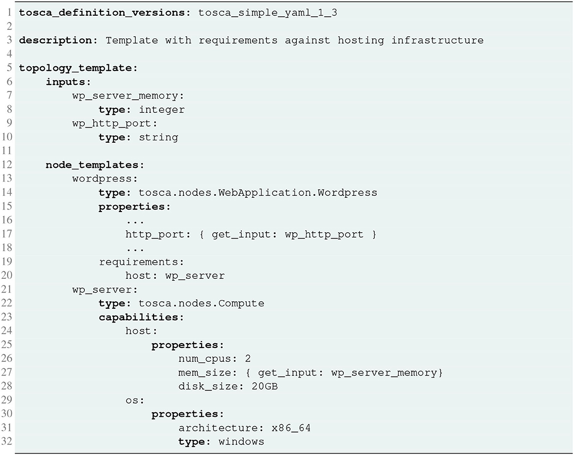
Figure 4. TOSCA simple node and hosted application definition.
The capabilities file section contains properties that allow application developers to optionally supply the number of CPUs, memory size, and disk size they believe they need when the Compute node is instantiated to run their applications. Similarly, the os capability is used to provide values to indicate what host operating system the Compute node should have when it is instantiated. In the example, input parameters defined in the inputs section can be assigned to properties of node template within the containing topology template, as for the mem_size property.
Figure 5 shows an example of the definition of an inter-requirement between different applications. In this example, we added a new software, a MySql database, to which the WordPress application needs to connect to obtain database services. The two applications are described by the topology node templates named, respectively, wordpress and wordpress_mysql_db, hosted, respectively, on the two tosca.nodes.Compute type nodes named wp_server and mysql_server. The node-type definition for the WordPress application node template declares the complete database_endpoint TOSCA predefined requirement definition. This database_endpoint declaration indicates that it must be fulfilled by any node template that provides an Endpoint.Database Capability Type using a ConnectsTo relationship. The wordpress_mysql_db node template's underlying MySQL type definition indeed provides the Endpoint.Database Capability type. The connection between the two applications is provided by the relationship template named wp_db_connection, which adds the inter application property named latency to the default ConnectsTo TOSCA type; the presence of such a relathionship between the requirements of the wordpress node template means that a latency of 20 ms is required in the connection between the two applications.
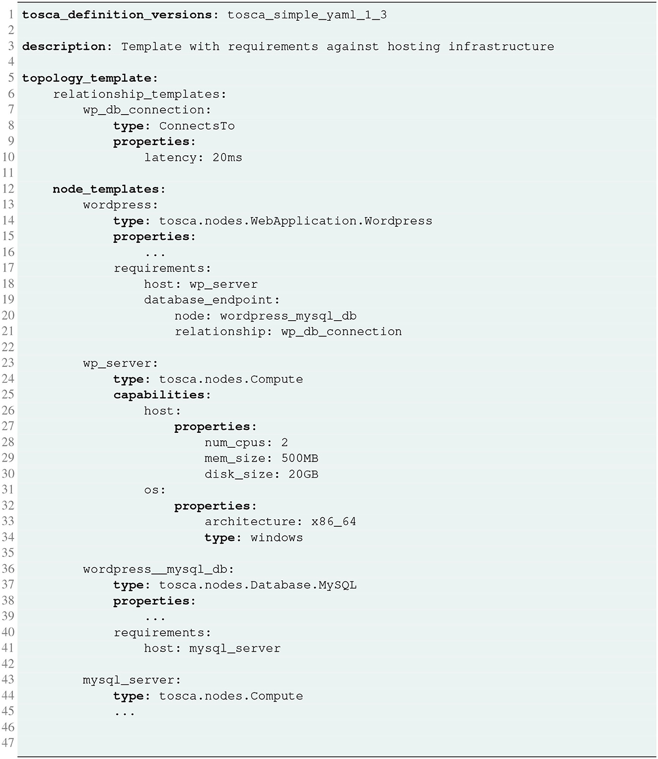
Figure 5. TOSCA example of a two-tier application with the latency inter requirement definition.
4.2.3.2. The application description and management subsystem
Once received, the application definition provided in TOSCA is parsed. SMARTORC uses an internal representation to work with the applications. Applications can thus be rendered using different formats and models to adapt to different deployment backends. This subsystem must also support changing the application structure during the orchestration process and its potential reenactment during the application lifetime, e.g., to increase the number of instances of some of the (micro-)services composing it and perform a scale-up.
The structure of the subsystem integrating all the functionalities needed for the management of application descriptors is presented in Figure 6. The Application Description and Manipulation subsystem exposes a single interface called Application Upload devoted to the upload of the application descriptor on SMARTORC. SMARTORC supports CRUD (Create, Read, Update, Delete) operations on the applications uploaded, the parsing of such applications and, eventually, the rendering into the target representation format (e.g., Kubernetes deployments). Each functionality is provided by distinct software modules, namely, Application Descriptor Manager, Application Model Parser, Application Model Renderers. Altogether, these software modules realize the Application Model Management. The functionalities and the capabilities implemented by the Application Model Management software are provided by SMARTORC through the Application Descriptor Manipulation service. Such a service is involved in two processes: Application Placement and Runtime Application Management.
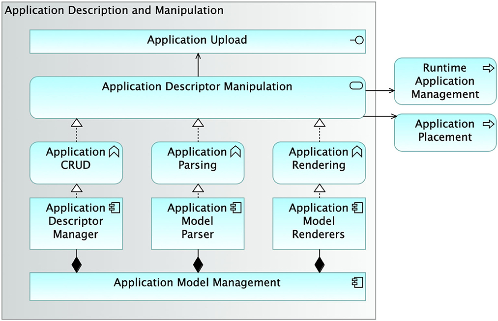
Figure 6. Architecture of the module supporting application description and manipulation.
4.2.4. User management
SMARTORC has been designed to manage requests from two different kinds of user roles: end users and administrators. Administrators perform tasks typical for this kind of role, e.g., system management, user management, system configuration, and so on. In addition, in SMARTORC, administrators' activities are also related to adding or removing edge data centers to the list of those used for application placement. SMARTORC embodies a dedicated subsystem devoted to user management. Figure 7 depicts the actual structure of the User Management subsystem. The subsystem exposes two interfaces, one for User Registration and another for User Login. These interfaces relate to two processes, allowing for User Registration and User sign-on, respectively. The activities conducted by these two processes are provided through the Authentication service, whose functionalities enable CRUD operations on users. The Authentication service is also designed to support login through external credentials. The software that implements all the functionalities of User Management is called Security Management. It does interface with the data stored into the User Registry.
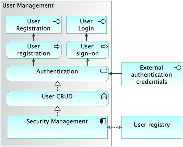
Figure 7. Architecture of the user management module. CRUD, create, read, update, delete.
4.2.5. Object store
To perform its activities, SMARTORC needs to store and access data of various kinds, ranging from monitoring information to application requirements, including user identification data as well as application status information. All the information needed by SMARTORC to orchestrate and manage applications is encapsulated within the SMARTORC ObjectStore, which is a software component that provides a flexible solution for the management of data within SMARTORC. Its interfaces address the actual needs of the tasks undertaken by the various SMARTORC subsystems. The ObjectStore abstraction is also a tool to encapsulate the different needs of SMARTORC components in such a way that initially a simple, off-the-shelf, and portable storage solution can be used to speed up the development. More complex and feature-laden solutions can be swapped in later to tackle higher performance and scalability of the orchestrator, as well as exploit decentralized storage management.
Figure 8 depicts the ObjectStore subsystem, the three main categories of information it manages and the modules accessing those information categories. The User registry keeps track of all the information concerning users for the needs related to authentication and authorization. It is accessed by the Security Management module. The Application Repository stores all the representations (both internal and external) of the applications managed by SMARTORC. The software module that has read/write access to these data is Application Model Management. Finally, the Resource Index manages data related to the resources that can be used in the application placement process and runtime application management. Resource Indexing and Discovery feeds this data repository with information concerning the edge data centers that can be used to host application instances. Last but not least, the Mapping Planner software module is the one module of SMARTORC fully exploiting the ObjectStore, having read/write access to the entire set of information it manages.
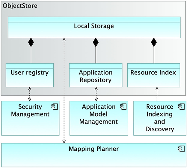
Figure 8. Architecture of the object store module.
4.2.6. Interfaces and processes
The SMARTORC system comprises several interfaces, processes, and services that collectively embody its functionalities and capabilities. The illustration in Figure 9 provides a bird's-eye view of the architecture. It highlights the mechanisms exposed, the processes activated by these mechanisms, and the services that implement the business code for these mechanisms.
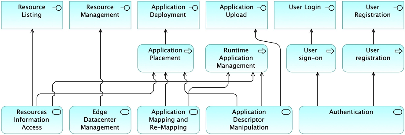
Figure 9. Overall representation of the SMARTORC interfaces, processes, and services.
It is worth noting that almost all processes and services are initiated by an interface mechanism, with the sole exception of the Runtime Application Management process, which is activated autonomously through active monitoring and observation of an application.
5. SmartORC prototype
In this section, we present the key technologies and provide details about the current prototype of SMARTORC. However, we do not provided a comprehensive description of all SMARTORC modules, as it goes beyond the scope of this article. The current prototype of SMARTORC primarily stems from the prototype used in the H2020 ACCORDION and H2020 CHARITY projects. It was developed in Python and follows a mostly centralized structure, incorporating many of the modules described in Section 4.
The prototype manages both requests from application owners (the end users) and requests concerned with the addition or removal of edge data centers (performed by administrators). Such a prototype is based on an HTTPS RESTFul interface defined using the OpenAPI 3.1 standard (OpenAPI, 2021), a YAML-like declarative language-agnostic interface to HTTP APIs, to allow for easier management and modification of the interface itself. SMARTORC has been designed to work with applications described utilizing the TOSCA description language, using the TOSCA Simple Profile for YAML 1.3 (OASIS, 2020) specifications; such a description mainly provides information about (1) the application components and the associated topology; (2) the requirements, for each application component, in terms of resources as well as QoS/QoE parameters; and (3) the recovery actions needed to be performed by the orchestrator when any QoS/QoE requirement of a component is violated. The application description is provided through the interfaces, together with the required operations (i.e., deployment, undeployment, scale-up, scale-down, etc.) and additional optional parameters, using the JavaScript Object Notation (JSON) format for the request message. The TOSCA application description is parsed using the OpenStack project's parser,3 a well-documented parser developed by the OpenStack Community that is easy to use, highly maintained, and adherent to the TOSCA Simple Profile for YAML specification. After parsing the application requirements, specified by the TOSCA description, these requirements are translated into an internal representation, and the status of the compute continuum resources is retrieved from the ObjectStore module. Such information is stored in an SQL-based database (currently SQLite) and provided by the RID module.
As described in Section 4, the main objective of the RID is to retrieve updated information about the availability of resources belonging to the continuum in a scalable and reliable way: such a result is achieved by exploiting a Distributed Hash Table (DHT)-based Peer-To-Peer (P2P) overlay network. In the current prototype, RID is based on an implementation of the well-known Kademlia network (Maymounkov and Maziueres, 2002), where each key represents the name of a monitored resource. Each agent of the Kademlia overlay network is distributed and deployed on each compute continuum data center. The local RID agents periodically collect up-to-date information about resources from (potentially different) local monitoring mechanisms offered by the edge data centers or triggered by custom policies exploiting the query mechanism provided by the Kademlia DHT. In the actual implementation, the local agent can be interfaced with Prometheus,4 largely diffused in edge/cloud environments.
Application descriptions, the list of users and their roles, and the status of the resources belonging to edge data centers are stored by the ObjectStore module in an SQLite database. The SMARTORC solver is based on the Python-MIP library,5 a collection of Python tools for modeling and solving MILPs. It executes a Branch-&-Cut (BC) algorithm that will provide the exact optimal solution in a finite time. Python-MIP was written to be deeply integrated with the C libraries of the open-source COIN-OR Branch-&-Cut (CBC) solver.6
Finally, recovery actions and the result of the matchmaking for deployment and undeployment actions are converted into a set of K3S/K8S Kubernetes configuration files. Kubernetes is a largely used, well-documented open-source framework leveraged to orchestrate and manage the local resources of edge data centers efficiently. All the implemented modules have been packaged as a unique service accessible by the front-end REpresentational State Transfer (REST) interface and released as a Linux-based Docker 7 container to be easily deployed and integrated into a preexisting environment.
5.1. Scalability concerns with MILP and mitigation
Despite having the ability to find optimal allocation solutions, MILP-based approaches do not scale well when the size of the problem grows and possibly result in significant delay when searching for viable matches. The growth in size of the MILP problem instance and the correspondingly increasing algorithm execution time are well-known limitations of these kinds of optimization approaches. To address the issue, we selected two approaches: a hierarchical one, which is being adopted in the current version of the prototype, and a fully decentralized approach that is currently under development and will be the core of the next version of SMARTORC. The details of the two version are give in Sections 5.1.1 and 5.1.2, respectively.
5.1.1. Hierarchical structure
To address the scalability issues that affect MILP-based approaches, we adopted a solution that is inspired by the ETSI Zero touch network and Service Management (ZSM)8 standard and, more specifically, its decomposition in End-To-End (E2E) and domain-specific orchestrators. The E2E orchestrator focuses on the overall systems (or, in other terms, having a bird's-eye view of the resources belonging to the entire systems), while the domain-specific one manages the physical resources that will materially host the applications.
We advocated this perspective in developing the hierarchical SMARTORC: a higher level module, called Sauron, behaving as an E2E orchestrator, receives all the requests and aggregates these requests in batches of configurable size. The E2E orchestrator does not directly manage resources but interacts with SMARTORC instances (see Figure 10). It does not work at the granularity of a single application, operating instead on batches of applications, checking the viability of the proposed assignment only in an aggregate form (i.e., if the sum of the application requirements in a batch is satisfied by the aggregate set of resources managed by a given SMARTORC instance).
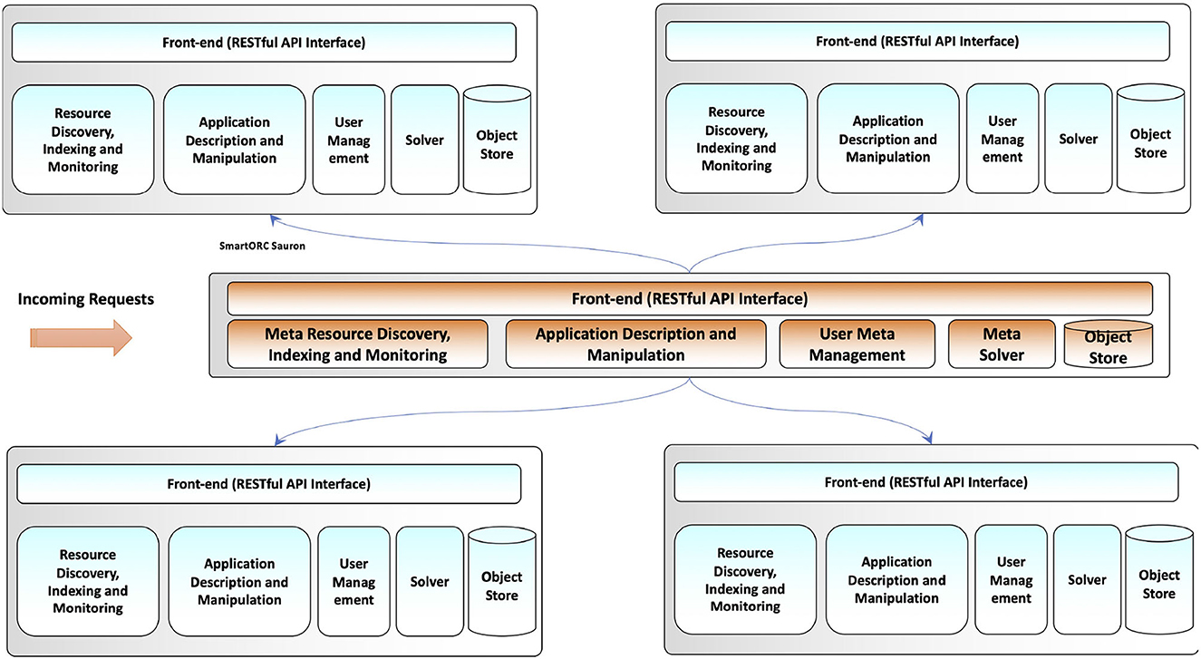
Figure 10. Hierarchical SMARTORC API.
This solution trades off some efficiency in resource usage and some efficacy of the orchestration to achieve a better scalability. The approach could in principle lead to a suboptimal exploitation of resources, from the viewpoint of some of the applications. Besides, by keeping the decision process at an aggregated level, it may happen that a batch cannot be allocated as a whole to the resources managed by a SMARTORC instance, e.g., because the aggregation of requirements results in too many constraints over the same set resources. Working on aggregates of requests can thus trigger an error at deployment time.
5.1.2. Fully decentralized structure
We are also devising a completely decentralized structure for SMARTORC. The main idea behind this approach is to reduce the size of MILP problems by restricting the application of MILP-based solvers to small amount of resources. In practice, we assume that the compute continuum at the edge comprises many small collections of resources. These entities can manage and carry out direct requests for the execution of applications. They can assign computational duties to their internal resources using their MILP solver components. Since MILP problems will have a limited dimension and size, the approach can result in an optimal assignment with acceptable computational overhead. However, to avoid unbalanced scenarios, such a system should implement mechanisms for harmonizing the overall exploitation of the system resources as a whole. To be effective, we decentralized the intelligence of the system, allowing each of its single components to communicate, collaborate, and coordinate with each other. We aim at optimizing the distribution of the applications executions with respect to both their functional and non-functional requirements.
These results can be obtained by decoupling the activities of the Solver component. On the one hand, the Solver manages and takes decisions about application execution assignments that remain inside a single SMARTORC instance. On the other hand, it has to manage the communication and coordination phases for taking collaborative decisions with other SMARTORC instances. More specifically, the RID component is used to let each entity become aware of the characteristics and feature of other entities in the system. In case of limited resources, a SMARTORC entity uses a function for ranking the other entities (e.g., the closer ones in term of latency), thus selecting and keeping the information of its top-k neighbors. Coordination with other entities happens in time either periodically or as triggered by need (e.g., an entity has exhausted its resources and cannot process any more incoming requests). Using the descriptions, a SMARTORC entity can select what other SMARTORC instances to communicate with. In their respective Solver components, the SMARTORC instances exploit a proper consensus-based evaluation and coordination scheme that allows them to exchange the applications they are executing to realize an optimized allocation of workloads. Such a scheme should work on the resources of the involved instances and the QoS/QoE limits posed by the associated applications.
While the final configuration could be less precise than a MILP-based application assignment, the decentralized nature of the decision-making process makes it far more scalable and adaptive, allowing a SMARTORC-based decentralized solution to efficiently and effectively manage large-scale scenarios of edge resources.
6. SmartORC assessment
As mentioned above, a prototype of SMARTORC is currently used in the H2020 ACCORDION9 and H2020 CHARITY10 projects that are still actively developing their technological frameworks. In such contexts, SMARTORC deeply interacts with (and is tailored to) other modules specific to each project (e.g., life-cycle manager, monitoring subsystem, etc.). In this article, we have assessed the SMARTORC prototype in isolation. As a matter of fact, a number of amendments to the prototype were needed and have been already implemented to integrate it within the projects' SW infrastructures. However, an evaluation of those projects is beyond the scope of this article, which is mainly focused on the design of SMARTORC. We thus considered the synthetic benchmark approach the only one viable for the assessment of SMARTORC on its own. The main objective of the experiments described in this section is the validation of the overall design and the key architectural choices underpinning SMARTORC and is not to provide a comprehensive demonstration of the efficacy of the Solver in the current SMARTORC prototype (e.g., quality of the solution to the matchmaking problem).
To validate SMARTORC concerning its ability to be a viable solution in the context of a large set, dispersed set of resources available at the edge, we conducted a number of experiments on the “amended” prototype. In particular, we conducted distinct sets of experiments to validate both the hierarchical version of the current prototype and the fully decentralized solution that will be the next release of SMARTORC.
Section 6.1 discusses the results of the evaluation conducted on the hierarchical version of our proposed orchestrator in two different scenarios and reports on the results achieved, highlighting the differences in terms of time spent (thus its potential scalability) to calculate the solution between a flat version of SMARTORC and a two-layer version.
In Section 6.2, we present some figures on the performance achieved by key algorithms that will be part of the next fully decentralized release of SMARTORC, which focuses on application placement without relying on centralized components, to improve the scalability even further. The assessment has been performed using the PureEdgeSim simulator (Mechalikh et al., 2019). To investigate the potential and flexibility of SMARTORC, we evaluated it under challenging conditions.
6.1. Evaluation of hierarchical SmartORC
To assess the viability of a multilayered version of SMARTORC in its attempt to overcome the limitation of MILP-based matchmaking processes in terms of scalability, we conducted two sets of experiments, each set run using a different scenario.
One scenario considers a larger set of different edge data centers (70 EMs) but lower contention (500 app instances); the other considers a smaller set of data centers (50 EMs) but with higher contention (400 app instances).
The requirements declared by each application, in terms of resources, are the following:
• CPU cores: randomly generated in the range [1,8]
• Random Access Memory (RAM): randomly generated in the range [128, 1,024] MB
• Storage: randomly generated in the range [10, 128] GB
Concerning the resources, all the experiments were performed using an homogeneous set of resources, but the capabilities change experiment by experiment. In all our experiments, we fixed the number of nodes managed by each EM to 10.
More in detail, for the generation of resources, the parameters employed are the following for each node and resource type:
• CPU cores: randomly generated in the range [20, 100]
• RAM: randomly generated in the range [2,048, 4,096] MB
• Storage: randomly generated in the range [200, 1,000] GB
Both scenarios were simulated by running an instance of SMARTORC on a local Intel 4-cores i7600K CPU machine, with 16 GB of RAM and feeding it with a TOSCA file describing each application instance. SMARTORC processes the requirement file, performs the matchmaking using the internal MILP-based solver, and produces an output file with the final deployment plan, composed of a series of couples of the form (AppID, EMID), where the first is the unique ID of a certain application and the second is the unique ID of the EM on which deployment of the application will be attempted and the time, in seconds, needed to perform the matchmaking process. Available resources of EMs are also described into a file submitted to the RID subsystem interface, depicted to add edge data centers. Taking into account that each EM represents an administrative domain with the responsibility to manage 10 nodes, the “flat” version of the SMARTORC orchestrator, namely, the one that manages each single application and resource directly, attempts to solve the matchmaking problem over 700*10 = 7, 000 different nodes. However, to simulate the hierarchical scenario, the single instance of SMARTORC have been invoked multiple times: once to represent execution of Sauron, the E2E higher level orchestrator; Sauron is the entry point for users, receiving the request to deploy all the applications of a certain scenario. Then, Sauron attempts to solve the matchmaking process between the applications and EMs by aggregating their resources as reported in Section 5.1.1. After Sauron has produced its deployment plan in output, all the applications proposed to be deployed on the same EM are grouped together in a single batch, and a unique deployment request for each batch of applications is communicated by Sauron to the domain-specific SMARTORC instance of that EM; in our tests, the communication time is considered to be negligible with respect to the time spent by the Solver. Then, we invoked again the single instance of SMARTORC a number of times equal to the number of EMs involved in the requests produced by Sauron, simulating their domain-specific orchestrators. Later, we submitted a different request and the file describing the specific resources managed by the corresponding EM to each instance separately . Finally, each invocation produced an output file with the final local deployment plan, which could also be emptied in case the local optimization problem could not be solved as observed at the end of Section 5.1.1.
Figure 11 depicts the results achieved by SMARTORC in the two sets of experiments we conducted. Specifically, Figures 11A, C present the comparisons involving the flat version of the SMARTORC orchestrator with the hierarchical one that employs its multilevel architecture (involving Sauron as the E2E higher level module and domain-specific modules for each EM). The figures illustrate the amount of time (on logarithmic scale) requested to perform the matchmaking process. For the hierarchical version, we summed up the time spent by Sauron plus the mean of the time spent by the domain-specific modules; it is possible to note that each domain-specific module runs concurrently with the other ones in parallel on different EMs. As can be noticed, the multilayer version requires an amount of time that is two orders of magnitude smaller than the “flat” version.
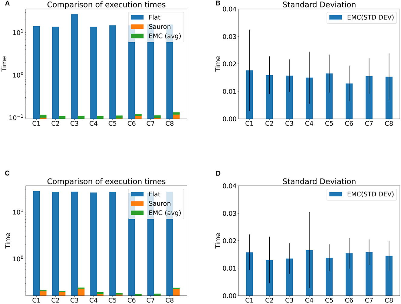
Figure 11. Hierarchical orchestration—experimental results with configurations of 50 and 70 EMs with 10 nodes each EM. (A) Execution time (50 EMs, 10 nodes each). (B) Standard deviation (50 EMs, 10 nodes each). (C) Execution time (70 EMs, 10 nodes each). (D) Standard deviation (70 EMs, 10 nodes each).
We can note that these results were obtained by reducing the dimension and size of the MILP problem performed separately by Sauron and each domain-specific orchestrator, with respect to the “flat” version. We have not applied any particular technique to approximate the optimization problem reported in Section 3, so we attempted to estimate the dimension of the problem in the “flat” version and in the hierarchical version, respectively, given the scenario with lower contention (the other scenario is similar), by calculating the number of decision variables and constraints to be solved by the Solver. Taking into consideration the model reported in Section 3, we can observed that the following list of parameters have the same values in both version:
• the number of applications: P = 500
• the number of resource types, Q = 3; furthermore, we can note that for each resource type, it is always true that finter(qj) = 0 and fnum(qj) = 1 with j ∈ {1, …, Q}.
For the second point, we can simplify the MILP problem by avoiding to calculate the constraints from groups (3) to (10) since there are no inter resources and all the resources are numerical. In this way, we can reduce our estimation, calculating only the number of decision variables xi, d with i ∈ {1, …, N} and d ∈ {1, …, P} and the number of constraints of sets (1) and (2).
Table 1 shows the parameters' estimation for the MILP problem in the case of the “flat” version, in the first row, and the hierarchical one; the second row is about the MILP problem solved by Sauron, while the third row is about the MILP problem solved by a domain specific orchestrator in the worst case, where all the applications have to be deployed on the same EM. The results show that the hierarchical version will lead to an optimization problem that is about ten times reduced in dimension respect to the “flat” version, validating the effectiveness of the hierarchical approach.
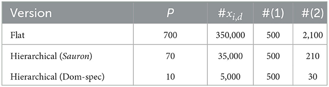
Table 1. Hierarchical and flat orchestration—estimation of the number of decision variables and constraints.
Figures 11B, D provide insights on the standard deviation concerning the time requested to perform the matchmaking by the domain-specific orchestrators running inside EMs. As can be noticed, the values vary considerably as the amount of application assigned by Sauron to each EM is different and depends on the decision taken by the Solver running inside the E2E orchestrator. The results showed that, in spite of the relatively high values of standard deviation, in any case, the time employed by the domain-specific orchestrator is far smaller than the one requested by the “flat” version of SMARTORC.
Whenever the E2E orchestrator becomes a bottleneck, it is possible to introduce further layers or increase the granularity of resources and application, letting each orchestrator work on a smaller set of items. A generalization of this approach is something that we did not consider in this article, but we plan to study it in future works.
6.2. Evaluation of decentralized SmartORC
As detailed in Section 5.1.2, we are investigating how the overall architecture of SMARTORC can be used in a purely decentralized environment. We refer the interested reader to Mordacchini et al. (2021) for a thorough description and an extensive evaluation of this scenario. We summarize here the main findings of those results to show the flexibility of SMARTORC and its effectiveness in such a difficult scenario. Indeed, the lack of complete knowledge and the potential limits in the communication range make this scenario far more challenging than an environment with a centralized orchestrator.
In the following experiments, we considered a setting with four distinct SMARTORC instances placed in a 200 × 200m-square area. The applications present in the system are of four different types: computational intensive, memory intensive, network intensive, and applications, where all the previous aspects are balanced. All the applications require that any deployment plan has to ensure that the served users are within a maximum allowable latency, a QoS constraint needed to guarantee a given application-specific QoE. For the experimental evaluation, we used 60, 120, and 180 different users randomly placed in the system. The users generate requests for applications. Such requests are uniformly divided among the available applications. In our scenario, a user ui initially requests an application Aj to the closest SMARTORC instance. In case the requested application is already running on that SMARTORC instance, the user is simply added to Aj users on that SMARTORC instance. If the SMARTORC instance does not have the requested application, we assume that it takes the requested application image from a remote repository before running it. This mechanism is very simple, and it initially ensure to limit of the latency between a user and the SMARTORC instance that is hosting the user's application. However, it could also lead to creating a plethora of replicated images of the same application running in different parts of the system. It is easy to imagine that it is possible to reduce these replicated applications by grouping their users on fewer SMARTORC instances without violating their QoS/QoE limits. As a consequence, the number of running applications can be reduced, thus saving resources and limiting the energy required to serve the same amount of users.
In the following problem, we assumed that the SMARTORC instances collaborate, using point-to-point communications. In case the instances run the same application Aj, the involved SMARTORC instances attempted to understand whether they can stop one of the two running images by referring all their users to just one of the SMARTORC instances. In doing this, they evaluated their respective computational loads, the computational requirements of Aj, and its QoS limits.
Table 2 shows how this coordination mechanism is able to reduce the overall amount of energy consumed in the system.

Table 2. Decentralized orchestration—relative energy consumption (footprint).
The table shows the evolution over time of the energy required by the entire system, including the energy needed for inter-communications between SMARTORC instances. The results are presented as the ratio between the energy needed at a time t > 0 and the energy consumed by the system at the beginning of the simulation at time t0.
It is possible to observe that the decentralized approach achieves a remarkable reduction of the energy consumed by the system, with more than a 20% reduction in the worst case. To do so, some users should refer to an application image placed in a SMARTORC instance that is different from the one they were originally assigned to. This fact could imply an increase in the latency experienced by the users. However, as shown in Table 3, this is a very limited variation. The table presents the ratio between the average user latency and the maximum latency admitted by their applications' QoS and QoE limits. Only a marginal increment occurs with respect to the initial situation. Therefore, this fact further confirms the ability of the proposed collaborative schema to optimize the placement of the applications in the system.
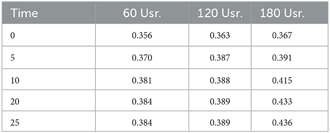
Table 3. Decentralized orchestration—users' average latency (in seconds).
7. Conclusion
The placement of applications on resources belonging to the compute continuum is a challenging task. Several approaches have been proposed in an attempt to solve this problem in an efficient and scalable way. SMARTORC aims at realizing these goals, stemming from research about supporting large-scale, interactive next-gen applications in the continuum. We discussed the design of SMARTORC and its key architectural choices along with some details of the prototype currently employed in two European research projects. In its current form, SMARTORC has a comprehensive component design that provides resource management capabilities on top of compute continuum resources. It is characterized by an intuitive and flexible architecture that can exploit several of the referenced approaches to orchestration in the compute continuum, including decentralized and hierarchical ones. We have also presented some promising preliminary results concerning the validation of the architectural choices. The experiments demonstrated that SMARTORC is a suitable solution for environments that need high levels of scalability and works with a large, dispersed set of resources.
Due to the modular and extendable design of SMARTORC, several improvement directions are already apparent, which pave the way for a complete framework implementation, for the introduction of additional capabilities, and for further research on management techniques, orchestration algorithms, and heuristics. One of the next steps is the complete definition of the interfaces between components, in terms of both technologies and the actual information that is passed along. This effort will systematize the implementation results from different projects and experimental activities, tying them into a common framework. Based on current design and implementation activities, more research opportunities will eventually emerge. We are currently planning the introduction of a “feedback channel,” where applications can provide structured information to SMARTORC to drive resource management, e.g., runtime values of application-specific metrics of QoS and QoE that are influenced by the dynamic resource allocation.
Data availability statement
The datasets presented in this study can be found in online repositories. The names of the repository/repositories and accession number(s) can be found below: https://www.smartorc.org.
Author contributions
All authors listed have made a equal and substantial intellectual contribution to the work and approved it for publication.
Funding
This work has been partially supported by ACCORDION H2020 and CHARITY H2020 projects under EC grant IDs 871793 and 101016509, respectively.
Conflict of interest
The authors declare that the research was conducted in the absence of any commercial or financial relationships that could be construed as a potential conflict of interest. The author MC declared that they were an editorial board member of Frontiers, at the time of submission. This had no impact on the peer review process and the final decision.
Publisher's note
All claims expressed in this article are solely those of the authors and do not necessarily represent those of their affiliated organizations, or those of the publisher, the editors and the reviewers. Any product that may be evaluated in this article, or claim that may be made by its manufacturer, is not guaranteed or endorsed by the publisher.
Footnotes
1. ^When applying the model to real resources, such instantaneous values are retrieved by querying the Resource Discovery, Indexing and Monitoring module, described in Section 4.2.1.
2. ^SmartORC website: https://www.smartorc.org.
3. ^https://wiki.openstack.org/wiki/TOSCA-Parser
5. ^https://www.python-mip.com
6. ^https://github.com/coin-or/Cbc
8. ^https://www.etsi.org/technologies/zero-touch-network-service-management
9. ^ACCORDION on CORDIS https://cordis.europa.eu/project/id/871793.
10. ^CHARITY on CORDIS https://cordis.europa.eu/project/id/101016509.
References
Ahmed, U., Al-Saidi, A., Petri, I., Rana, O. F. (2022). Qos-aware trust establishment for cloud federation. Concurr. Comp. Pract. Exp. 34, e6598. doi: 10.1002/cpe.6598
Albrecht, J., Oppenheimer, D., Vahdat, A., Patterson, D. A. (2008). Design and implementation trade-offs for wide-area resource discovery. ACM Transact. Int. Technol. 8, 1–44. doi: 10.1145/1391949.1391952
Altmann, J., Al-Athwari, B., Carlini, E., Coppola, M., Dazzi, P., Ferrer, A. J., et al. (2017). “Basmati: an architecture for managing cloud and edge resources for mobile users,” in International Conference on the Economics of Grids, Clouds, Systems, and Services (Cham: Springer), 56–66.
Aral, A., and Ovatman, T. (2018). A decentralized replica placement algorithm for edge computing. IEEE Transact. Netw. Serv. Manag. 15, 516–529. doi: 10.1109/TNSM.2017.2788945
Beraldi, R., Mtibaa, A., and Alnuweiri, H. (2017). “Cooperative load balancing scheme for edge computing resources,” in 2017 Second International Conference on Fog and Mobile Edge Computing (FMEC) (Valencia: IEEE), 94–100.
Binz, T., Breitenbücher, U., Kopp, O., and Leymann, F. (2014). “Tosca: portable automated deployment and management of cloud applications,” in Advanced Web Services (Springer), 527–549. doi: 10.1007/978-1-4614-7535-4_22
Carlini, E., Coppola, M., Dazzi, P., Mordacchini, M., and Passarella, A. (2016). “Self-optimising decentralised service placement in heterogeneous cloud federation,” in 2016 IEEE 10th International Conference on Self-adaptive and Self-organizing Systems (SASO) (Augsburg: IEEE), 110–119.
Casalicchio, E. (2017). “Autonomic orchestration of containers: Problem definition and research challenges,” in 10th EAI International Conference on Performance Evaluation Methodologies and Tools, VALUETOOLS'16 [Taormina: ICST (Institute for Computer Sciences, Social-Informatics and Telecommunications Engineering)], 287–290.
Cascella, R., Blasi, L., Jegou, Y., Coppola, M., and Morin, C. (2013). “Contrail: distributed application deployment under SLA in federated heterogeneous clouds,” in The Future Internet, eds A. Galis, and A. Gavras (Berlin, Heidelberg: Springer Berlin Heidelberg), 91–103.
Cattrysse, D. G., and Van Wassenhove, L. N. (1992). A survey of algorithms for the generalized assignment problem. Eur. J. Oper. Res. 60, 260–272. doi: 10.1016/0377-2217(92)90077-M
Chafle, G. B., Chandra, S., Mann, V., and Nanda, M. G. (2004). “Decentralized orchestration of composite web services,” in Proceedings of the 13th International World Wide Web Conference on Alternate Track Papers & Posters, WWW Alt. '04 (New York, NY: Association for Computing Machinery), 134–143.
Dazzi, P., and Mordacchini, M. (2020). Scalable decentralized indexing and querying of multi-streams in the fog. J. Grid Comp. 18, 395–418. doi: 10.1007/s10723-020-09521-3
Ferrucci, L., Mordacchini, M., Coppola, M., Carlini, E., Kavalionak, H., and Dazzi, P. (2020). “Latency preserving self-optimizing placement at the edge,” in Proceedings of the 1st Workshop on Flexible Resource and Application Management on the Edge (Stockholm), 3–8.
Korontanis, I., Tserpes, K., Pateraki, M., Blasi, L., Violos, J., Diego, F., et al. (2020). “Inter-operability and orchestration in heterogeneous cloud/edge resources: the accordion vision,” in Proceedings of the 1st Workshop on Flexible Resource and Application Management on the Edge (Stockholm), 9–14.
Kundakcioglu, O. E., and Alizamir, S. (2009). “Generalized assignment problem,” in Encyclopedia of Optimization, eds C. A. Floudas, and P. M. Pardalos (New York, NY: Springer US), 1153–1162.
Madhavapeddy, A., Mortier, R., Rotsos, C., Scott, D., Singh, B., Gazagnaire, T., et al. (2013). “Unikernels: library operating systems for the cloud,” in Proceedings of the Eighteenth International Conference on Architectural Support for Programming Languages and Operating Systems, ASPLOS '13 (New York, NY: Association for Computing Machinery), 461–472.
Maia, A. M., Ghamri-Doudane, Y., Vieira, D., and de Castro, M. F. (2019). “Optimized placement of scalable iot services in edge computing,” in 2019 IFIP/IEEE Symposium on Integrated Network and Service Management (IM) (Washington, DC), 189–197.
Maymounkov, P., and Maziueres, D. (2002). “Kademlia: a peer-to-peer information system based on the xor metric,” in Proc. First Int. Workshop on Peer-to-Peer Systems (Cambridge, MA), 53–65.
Mechalikh, C., Taktak, H., and Moussa, F. (2019). “Pureedgesim: a simulation toolkit for performance evaluation of cloud, fog, and pure edge computing environments,” in 2019 International Conference on High Performance Computing & Simulation (HPCS) (Dublin: IEEE), 700–707.
Mordacchini, M., Conti, M., Passarella, A., and Bruno, R. (2020). Human-centric data dissemination in the iop: large-scale modeling and evaluation. ACM Trans. Auton. Adapt. Syst. 53, 1–35. doi: 10.1145/3366372
Mordacchini, M., Ferrucci, L., Carlini, E., Kavalionak, H., Coppola, M., and Dazzi, P. (2021). “Self-organizing energy-minimization placement of QoE-constrained services at the edge,” in International Conference on the Economics of Grids, Clouds, Systems, and Services (Cham: Springer), 133–142.
Nauss, R. M. (2003). Solving the generalized assignment problem: an optimizing and heuristic approach. INFORMS J. Comput. 15, 249–266. doi: 10.1287/ijoc.15.3.249.16075
Ning, Z., Dong, P., Wang, X., Wang, S., Hu, X., Guo, S., et al. (2020). Distributed and dynamic service placement in pervasive edge computing networks. IEEE Transact. Parall. Distrib. Syst. 32, 1277–1292. doi: 10.1109/TPDS.2020.3046000
OASIS (2020). TOSCA Simple Profile in YAML. Technical Report. OASIS. Available online at: https://docs.oasis-open.org/tosca/TOSCA-Simple-Profile-YAML/v1.3/os/TOSCA-Simple-Profile-YAML-v1.3-os.html (accessed February 26, 2020).
OpenAPI (2021). OpenAPI 3.1 Specification. Technical Report, OpenAPI. Available online at: https://spec.openapis.org/oas/v3.1.0
Pollock, G., Thompson, D., Sventek, J., and Goldsack, P. (1998). The Asymptotic Configuration of Application Components in a Distributed System. Technical Report. University of Glasgow. Available online at: http://eprints.gla.ac.uk/79048/
Ross, G. T., and Soland, R. M. (1975). A branch and bound algorithm for the generalized assignment problem. Math. Programm. 8, 91–103. doi: 10.1007/BF01580430
Salaht, F., Desprez, F., and Lebre, A. (2020). An overview of service placement problem in fog and edge computing. ACM Comput. Surv. 14, 1–25. doi: 10.1145/3391196
Schmidt, S., Zadtootaghaj, S., Sabet, S. S., and Möller, S. (2021). “Modeling and understanding the quality of experience of online mobile gaming services,” in 2021 13th International Conference on Quality of Multimedia Experience (QoMEX) (IEEE), 157–162.
Sim, K. M. (2012). Agent-based cloud computing. IEEE Transact. Serv. Comp. 5, 564–577. doi: 10.1109/TSC.2011.52
Talagala, N., Sundararaman, S., Sridhar, V., Arteaga, D., Luo, Q., Subramanian, S., et al. (2018). “Eco: harmonizing edge and cloud with ml/dl orchestration,” in USENIX Workshop on Hot Topics in Edge Computing (HotEdge 18) (Boston, MA: USENIX), 1–7.
TheOpenGroupStandard (2019). Archimate 3.1 Specification. Technical Report. Bordeaux: The Open Group.
Toffetti, G., Brunner, S., Blöchlinger, M., Dudouet, F., and Edmonds, A. (2015). “An architecture for self-managing microservices,” in Proceedings of the 1st International Workshop on Automated Incident Management in Cloud, 19–24.
Vaquero, L. M., Cuadrado, F., Elkhatib, Y., Bernal-Bernabe, J., Srirama, S. N., and Zhani, M. F. (2019). Research challenges in nextgen service orchestration. Fut. Gen. Comp. Syst. 90, 20–38. doi: 10.1016/j.future.2018.07.039
Wen, Z., Yang, R., Garraghan, P., Lin, T., Xu, J., and Rovatsos, M. (2017). Fog orchestration for internet of things services. IEEE Int. Comp. 21, 16–24. doi: 10.1109/MIC.2017.36
Ye, Z., Zhou, X., and Bouguettaya, A. (2011). “Genetic algorithm based qos-aware service compositions in cloud computing,” in Database Systems for Advanced Applications, eds J. X. Yu, M. H. Kim, and R. Unland (Berlin: Springer Berlin Heidelberg), 321–334.
Youn, C.-H., Chen, M., and Dazzi, P. (2017). Cloud Broker and Cloudlet for Workflow Scheduling. Springer.
Keywords: compute continuum, orchestration, distributed computing, resource management, application deployment
Citation: Carlini E, Coppola M, Dazzi P, Ferrucci L, Kavalionak H, Korontanis I, Mordacchini M and Tserpes K (2023) SmartORC: smart orchestration of resources in the compute continuum. Front. High Perform. Comput. 1:1164915. doi: 10.3389/fhpcp.2023.1164915
Received: 13 February 2023; Accepted: 06 July 2023;
Published: 25 October 2023.
Edited by:
Rui Han, Beijing Institute of Technology, ChinaCopyright © 2023 Carlini, Coppola, Dazzi, Ferrucci, Kavalionak, Korontanis, Mordacchini and Tserpes. This is an open-access article distributed under the terms of the Creative Commons Attribution License (CC BY). The use, distribution or reproduction in other forums is permitted, provided the original author(s) and the copyright owner(s) are credited and that the original publication in this journal is cited, in accordance with accepted academic practice. No use, distribution or reproduction is permitted which does not comply with these terms.
*Correspondence: Patrizio Dazzi, patrizio.dazzi@unipi.it
†These authors have contributed equally to this work and share first authorship