The offshore renewables industry may be better served by new bespoke design guidelines than by automatic adoption of recommended practices developed for oil and gas infrastructure: A recommendation illustrated by subsea cable design
 Terry Griffiths1,2,3*
  Scott Draper1,2,3
  Liang Cheng1,2,3
  Hongwei An2
  Marie-Lise Schläppy1
  Antonino Fogliani1,2
  David White4 Stuart Noble5
  Daniel Coles6
  Fraser Johnson7 Bryan Thurstan3
  Yunfei Teng3
- 1Oceans Graduate School, The University of Western Australia, Perth, WA, Australia
- 2Department of Civil, Environmental and Mining Engineering, The University of Western Australia, Perth, WA, Australia
- 3Aurora Offshore Engineering, Perth, WA, Australia
- 4Department of Civil, Maritime & Environmental Engineering, University of Southampton, Southampton, United Kingdom
- 5Sealip Engineering, Rochdale, United Kingdom
- 6School of Engineering, Computing and Mathematics University of Plymouth, Plymouth, United Kingdom
- 7Simec Atlantis, Edinburgh, United Kingdom
Introduction: There is an emerging need for the offshore renewable industry to have their own bespoke design guidelines because the associated projects and offshore facilities differ in fundamental ways to oil and gas facilities. Offshore renewable energy (ORE) facilities have already surpassed the numbers of installed facilities in the oil and gas industry by an order of magnitude and demand is forecast to continue growing exponentially. In addition ORE facilities often have different response characteristics and limit states or failure modes as well as profoundly different risk and consequence profiles given they are generally uncrewed and do not contain explosive hydrocarbon fluids which might be released into the environment. Therefore, the purpose of this paper is to advocate for licensing bodies and regulators (such as the various national PEL 114 committees) to challenge the process of automatic adoption of oil and gas design processes, while pushing for offshore renewables to be treated differently, when appropriate, with more relevant and applicable guidance.
Methods: To support this argument we present new bespoke design guidance developed for subsea cables based on specific modes of cable behaviour, which often differ from pipelines. We also show worked examples from recent project experience. The results from on-bottom stability analyses of a set of cables are compared between conventional oil and gas guidance following DNV-RP-F109 versus the stability using cable-optimised approaches.
Results: The outcomes from the ‘conventional’ oil and gas results are not simply biased compared to cable-optimised design methods, with a trend of being either conservative or unconservative. Instead, the results of the two methods are very poorly correlated. This shows that the oil and gas approach isn't simply biased when applied to cables, but is instead unreliable because it doesn't capture the underlying failure conditions. These analytical comparisons are supported by field observation - the ocean doesn't lie, and makes short work of any anthropogenic structures which are designed with inadequate appreciation of the real world conditions.
Discussion: To support the rapid growth of ORE, we should therefore actively pursue opportunities to rewrite the design rules and standards, so that they better support the specific requirements of ORE infrastructure, rather than legacy oil and gas structures. With more appropriate design practices, we can accelerate the roll out of ORE to meet net zero, and mitigate the climate crisis.
1 Introduction
To alleviate future climate change humanity must reduce the reliance on fossil fuels for energy production by adopting renewable energy sources, primarily wind and solar (IPCC, 2021; UNFCCC, 2021).
To achieve this aim, the offshore renewables industry must grow exponentially. Current government targets of installed offshore wind capacity are approaching the value of 380 GW by 2030 that was proposed in the 2021 UN Energy Compact by the International Renewable Energy Agency (IRENA) and Global Wind Energy Council (GWEC) (GWEC, 2022). To meet this aim, tens of thousands of new structures and tens of thousands of kilometers of subsea power cable must be installed in the next decade. That growth rate needs to continue to 2050, when humanity must achieve net zero carbon emissions if global warming is to be limited to 1.5°C – which is a goal that most nations have now committed to.
The offshore industry is heavily regulated, partly due to its origin in oil and gas development, with the associated human and environmental risk. The design of offshore infrastructure is therefore tightly controlled through standard documents (or recommended practices). The adherence to standards has many benefits, but these documents evolve slowly, with revisions typically only approved twice per decade. In contrast, the climate crisis requires urgent rapid action.
1.1 Paper structure
The purpose of this paper is to highlight that bespoke new design guidelines may be more appropriate for the emergent but rapidly-growing offshore renewables industry, rather than adopting legacy practices from the offshore oil and gas industry. The paper is structured as followed:
● Section 1 sets out the industry context, and introduces the engineering challenge of cable stability design. We discuss how cable stability could be tackled by borrowing approaches from oil and gas pipeline stability design, but we highlight the flaws in this approach.
● Section 2 discusses the background to standards, recommended practices and engineering reliability. We show how the underlying mechanisms of failure and limit states differ between cables and pipelines.
● Section 3 and Section 4 introduce bespoke approaches for cable stability design, for rocky and sandy seabeds respectively. These methods have a different basis to the conventional approaches inherited from oil and gas experience. Practical case studies are used to illustrate their performance.
● Section 5 closes the paper with conclusions.
1.2 Industry context: offshore oil and gas vs. offshore renewables
Following the establishment and growth of the offshore oil and gas industry in the mid 1960’s, major research centered on the North Sea has been undertaken through until the 1990’s to develop and refine the models of behavior for subsea oil and gas pipelines used to transport and export production to shore for further processing. These design methods have been codified into recommended design practices, with the family of guidance published by DNV having become globally ubiquitous, despite their lack of substantial evolution or refinement over the last two decades. The widespread adoption of these design methods has resulted in remarkably few catastrophic oil or gas pipeline failures over this time.
In 1991, the world’s first offshore wind farm (OWF) was established off the coast of Vindeby, Denmark. Since that time, the offshore wind industry has grown rapidly and now contributes a significant fraction of the total electrical power supply in some locations. During 2021, the total global installed capacity is reported to have reached 57 GW (GWEC, 2022) – hence despite exponential growth, the offshore wind industry lags roughly 3 decades behind the oil and gas industry in evolutionary terms.
For comparison purposes, it is reported that there presently exist around 184 offshore oil rigs in the North Sea (Statista, 2023). In contrast, it is reported that there are presently approximately 4000 offshore wind turbines in the same area (Crown Estate, 2022). This means that the offshore wind industry has already built over an order of magnitude more ocean-founded structures than the oil and gas industry that is twice its age. These offshore wind structures are almost universally uncrewed, whereas the majority of the oil and gas structures are crewed. The future prospects for the oil and gas industry are for very few new platforms to be installed, whereas in stark contrast the 2030 targets for installed offshore wind capacity are 65 GW for the European Union (EU) bordering the North Sea (through the Esbjerg Declaration, 2022) and 50 GW for the United Kingdom (UK) (HMG, 2022). These targets represent increases of around 49 GW (EU) and 39 GW (UK) and correspond to a combined increase of around 5,000 to 8,000 turbines in the next 8 years depending on how quickly these turbines increase in unit power. This represents exponential growth on the present offshore wind installed capacity, meaning that ‘business as usual’ design and engineering practices should be subject to review and challenge for their suitability going forwards.
1.3 Prevalence and industry drivers
The vast majority of offshore wind developments have, to date, been located in shallow coastal areas on soft sediments including sand and clay – resulting in the widespread adoption of trenching and burial of the inter-array and export power cables to negate the risks of instability due to hydrodynamic loading and third-party mechanical damage. It has therefore been expedient for the marine renewables industry to adopt the subsea pipeline design practices from the oil and gas industry for application to array and export cables, and use them to model the on-bottom stability and allowable spanning of the cables. Despite the high reliability of subsea pipelines in the oil and gas industry, the integrity of offshore renewable energy cables has been found to be much less reliable - over 80% of insurance claims by the offshore wind industry have been attributed to cable failures (Boehme and Robson, 2012; Jee, 2016). This is despite the integrity of cables being critical to the financial performance of these projects. The suitability and applicability of the existing body of oil and gas design guidance for application to cables is therefore worthy of review.
Over the last few years, the offshore renewables industry has begun expanding into new areas, including:
1. Shallow coastal windfarms located in areas prone to the rapid onset of severe cyclonic storm conditions during cable lay operations – leading to challenging on-bottom stability conditions during the installation phase prior to cable burial.
2. Shallow coastal windfarms in areas prone to severe metocean conditions (such as off the Atlantic coast of Europe) where persistent breaking waves sweep the seabed clear of sediment, resulting in the cables needing to remain exposed on the seabed during their operational lifetime.
3. Floating wind farms (for example off the west coast of Norway), where seabed conditions typically comprise exposed bedrock.
4. The further development of wave and tidal stream energy where the presence of strong and persistent tidal currents and/or waves also leads to seabeds featuring exposed bedrock and power export cables subject to implausibly high hydrodynamic loads.
5. The construction of major subsea High Voltage Direct Current (HVDC) interconnector cables to join different electricity networks, for example between Norway and Germany, to enable balancing of hydro and wind power production with variation in consumption demand in each network.
The on-bottom stability design of subsea pipes is important to ensure safety and reliability but can be challenging to achieve, particularly for renewable energy projects which are preferentially located in high energy metocean environments. Often, these conditions lead to the seabed being stripped of all loose sediment, leaving the cables to rest on exposed bedrock, boulders or cobbles where roughness features can be similar in size to the cables. As novel offshore renewable energy projects such as tidal stream energy, floating wind and wave energy devices increasingly evolve from concept demonstration to commercial-scale developments, new approaches are needed to capture the relevant physics for small diameter cables on rocky seabeds to reduce the costs and risks of power transmission and increase operational reliability. Similarly, where shallow water depths and unpredictable severe storms can occur during the cable installation phase, novel design approaches that capture more of the true tripartite interaction between cables, seabeds and fluid forcing have the potential to unlock significant improvements in reliability and reductions in costs for the marine renewable energy industry. In reality, the power cables are agnostic to whatever is attached at each end from the perspective of seabed/fluid interaction.
1.4 On-bottom stability: an exemplar of knowledge transfer between oil and gas and renewables
Subsea pipeline on-bottom stability is adopted herein as a convenient and relevant design aspect to study the evolution and refinement of the design approaches by the oil and gas industry, followed by the widespread adoption of these same approaches in the offshore renewables industry.
On-bottom stability design aims to ensure that pipelines do not move excessively on the seabed under loading actions from waves and currents. Design guidance for subsea pipeline on-bottom stability has evolved over approximately 5 decades from the publication of:
1. DNV ‘76 Rules for Submarine Pipeline Systems (DNV, 1976), where the design approach adopted absolute stability as a force-balance between stabilizing friction and destabilising hydrodynamic forces.
2. DNV ‘81 Rules for Submarine Pipeline Systems (DNV, 1981) where significant refinement in the hydrodynamic force model was introduced following extensive industry research;
3. DNV-RP-E305 (DNV, 1988) where enhanced models of lateral resistance and dynamic stability methods were introduced, together with calibrated methods for capturing typical results from many dynamic simulations.
4. DNV-RP-F109 (DNV, 2008; DNV, 2021a). First issued in 2008 then reissued in 2011, 2017, 2019 and 2021 each revision has introduced minor incremental edits and adjustments to the above design approaches. For simplicity hereon this recommended practice is referred to as ‘F109’.
At the Offshore Marine and Arctic Engineering (OMAE) 2008 conference in Estoril Portugal, Zeitoun et al. (2008) summarised the ‘state of the art’ in key aspects of pipeline on-bottom stability design processes, including the above historical perspectives. Zeitoun et al. (2008) discuss the advantages and shortfalls of the different design approaches in order to aid the reader’s understanding.
Since that time, a decade of research and further methodology refinement has extended the boundaries of the industry’s knowledge and understanding of the behaviour of subsea pipes, including geotechnics, hydrodynamics, oceanography and structural response modelling. Particular progress has been made in:
1. The response of pipelines to sediment transport and scour.
2. Understanding the behaviour of small diameter pipelines and cables within wave and current boundary layers.
3. The behaviour of cables on rocky seabeds in high energy marine environments.
Despite this extensive body of research findings, negligible change or enhancement to either of the prevailing design approaches in widespread use around the world: F109 (DNV, 2021a); and the American Gas Association (AGA) pipe stability software tool developed by Pipeline Research Council International (PRCI). AGA (2002) has been made to incorporate these improvements.
Since the publication of the Zeitoun et al. (2008) overview of the then-state-of-the-art in pipeline on-bottom stability design, a number of major research efforts have been undertaken, some of which are still works-in-progress. There has also been the design, construction and initial operation of a number of significant subsea pipelines offshore Australia and elsewhere. The learnings from undertaking the design for these projects has filtered into the public domain via a number of academic and industry conferences and publications. Together these include:
1. The University of Western Australia (UWA) O-tube project as a cornerstone of the STABLEpipe Joint Industry Project (JIP), including the Australian Research Council-supported On-Bottom Stability of Large Diameter Submarine Pipelines Linkage Project LP0989936 (Cheng et al., 2009) and Hydrodynamic Forces on Small Diameter Pipelines Linkage Project LP150100249 (Cheng et al., 2015).
2. The DNVGL-led StabUmCa and PILS JIPs (Vedeld et al., 2018), which had claimed to focus on cable stability.
3. Wood Plc-led ongoing methodology development and research including a number of sponsored UWA CEED projects (for example Shen et al., 2013), as well as the Cability JIP led by the Paris office, which also aimed to specifically focus on cable stability.
An updated summary of the research contributions made over the last decade in this field has been provided by Griffiths et al. (2018a). These works point to a broad body of expertise and industry understanding gained from the use of existing recommended practices in design, such as the commonly-used F109 (DNV, 2021a), and the less-well-used but still-relevant AGA/PRCI design methods (AGA, 2002). Each of these practices have a ‘family’ of antecedent incarnations which vary imperceptibly from one to the next, with the overarching design architecture having remained largely unchanged for decades. Where pipe (or cable) on-bottom stability is not excessively onerous and where conventional metocean, geotechnical and pipe properties are relevant, these families of design approaches are characteristically employed within the offshore industry and considered to be broadly conservative and utilitarian within their limiting bounds of validity.
Each of these families of design approaches adopts one of three distinct methods:
1.4.1 Absolute stability method (F109 Section 4.5)
The absolute stability design method evaluates the stability of the pipe by considering its submerged weight and diameter, the environmental forces acting on the pipe, and the resistance acting on the pipe from the seabed soil as a balance of loads divided by resistances, adjusted by a safety factor in accordance with:
where γsc is the required safety factor based on safety class and geographic location, and are the horizontal and vertical forces associated with the single largest design wave plus current, after factoring to allow for embedment or trench shielding, μ is the Coulomb friction factor, ws is the pipeline or cable submerged weight per unit length and FR is the passive soil resistance for sand and clay soils.
The approach is described as a ‘single design wave’ method which looks to determine the largest anticipated wave (H*) and its associated period (T*). In conjunction with the relevant design near-bed current the near-bed velocity U* is found in order to calculate the maximum hydrodynamic forces experienced by the pipe, which it is required to resist without movement based on the available lateral resistance from the soil, which is calculated from active and passive friction accounting for any embedment.
The above limit state criteria only makes logical sense when the pipe can be treated as being prismatically uniform along its longitudinal axis, leading the stability problem to degenerate to a two-dimensional behavioural model. In practice no pipes are ever prismatically uniform, however that is profoundly so for cables placed onto rocky seabeds where the vast majority of the cable is suspended above the seabed with only occasional localized points of contact occurring. In the case of the MeyGen cables Griffiths et al. (2018b) found that less than 1% of the cable length was in contact with the seabed. Under these conditions, the limit state proposed by DNV in Eq (1 above) only makes logical sense as a length-averaged condition, recognising that a natural consequence of this longitudinal averaging is that some intermediate pipe movement may occur as a result, for example at each spanning section between touchdown points.
1.4.2 Calibrated stability methods
The AGA Level 2 and DNV Generalised Lateral Stability methods calculate the required submerged weight for the given environmental conditions against a set of calibration coefficients that have been determined from the performance of large numbers of dynamic stability analyses using ‘sand’ and ‘clay’ seabed types. The coefficients have been calibrated to result in no more than the target level of lateral displacement (for DNV, equivalent of 10 D lateral movement, or 0.5 D lateral movement dependent on the criteria selected, where D is the external diameter of the pipe or cable). The validity of analysis performed to this design method is dependent on the validity of the underlying assumptions implicit within the proscriptive method – pipe surface coating, presence of marine growth and soil properties are either absent or profoundly simplified.
1.4.3 Dynamic stability
Seabed stability analysis may be carried out in accordance with AGA Level 3 or F109 dynamic stability method. Time-domain solvers have been developed by DNV through the PILS JIP (Vedeld et al., 2018) and by industry (Zeitoun et al., 2009; Youssef et al., 2011; Abdolmaleki and Gregory, 2018). These predict the 1D (lateral), 2D (lateral and vertical) and 3D (lateral, vertical and longitudinal) solutions for pipe displacement as a function of time resulting from a simulated near-bed velocity storm time-series. The methods incorporate corrections to hydrodynamic forces and lateral resistance for pipes partially embedded in ‘sand’ or ‘clay’ seabed types as described in Sections 6.4 and 7 of F109. The objective of a dynamic lateral stability analysis is to calculate the lateral displacement of a pipe subjected to hydrodynamic loads from a given combination of waves and current during a design sea state.
Displacements are extracted for a number of random seeds from the analysis, with reported displacement being equal to the mean value plus one standard deviation, as specified in F109. No user guidance is offered by DNV for 3 dimensional simulations on whether the mean plus one standard deviation on displacement should consider the mean and standard deviation of the displacement along the model pipe, as well as the mean and standard deviation between the 7+ simulations – this issue has been explored by Robertson et al. (2015).
In terms of work specifically focussed on small diameter pipes, relatively little has been published from the DNV-led StabUmCa and PILS JIPs. Vedeld et al. (2018) provides some insight into both of these research programs, which were intended to provide new design guidance to reduce unnecessary conservatism for smaller diameter pipes, however the resulting research outcomes are limited to consolidation of a small quantum of the existing and decades-old published body of knowledge of pipe on-bottom stability design. No new experimental or other research has been produced through these costly programs, which to-date have not been reflected in the incorporation of new and updated design guidance in F109 – albeit the most recent (2021) revision to the recommended practice claims without substantiation that the guidance is relevant to umbilicals and cables.
1.5 Stability and spanning of small diameter cables and umbilicals: fundamental differences compared to pipelines
Subsea power cables and umbilicals differ to typical oil and gas pipelines in a number of important aspects as follows:
1. A cable is smaller than a pipeline. This means that for a given flow condition, the cable is located more deeply into the miasma of the near-bed boundary layer, resulting in the ratio of wave loading often increasing relative to steady current loading. Being much smaller than typical oil and gas pipelines means the effects of wave boundary layers are far more pronounced and should be accounted for in design.
2. This smaller diameter also means that often cables and umbilicals experience design wave conditions which exceed the tested range of Keulegan-Carpenter number values which inform the underlying hydrodynamic model embedded in F109, hence leading to an uncertainty in the validity of the limiting hydrodynamic force coefficients.
3. In general, the average specific gravity (SG) of a cable is much higher than for a hydrocarbon pipeline (typically 50-100%). Despite this being typical, because the submerged weight varies with D2 and the hydrodynamic forces vary with D, it is possible to show (using conventional design methods) that a solid gold bar will be deemed unstable at a certain small diameters, as illustrated in Figure 1.
4. On rocky seabeds the pipe or cable is not able to become embedded. So it rests on the seabed with frequent meso-scale spans between points of contact as shown in Figure 2. The vast majority of the cable is therefore in span with only point contacts supporting the cable. This behaviour is relevant to offshore renewables because their cables are often situated in high energy metocean conditions (tidal or wind-driven seas) and their compliance considering their lower stiffness (axial and bending) is an advantage to be considered and enjoyed. A conventional steel-pipe on flat-rock model overlooks the above.
5. The structural response of a pipeline is dominated by the steel element, with the internal and external coatings having minimal influence. In contrast, a cable is a composite structure with many different material layers, including steel strips or wire in a woven form, rather than solid tubing. As a result, the structural properties of cables differ significantly from pipelines, with cables having lower bending and axial stiffness and much higher hysteretic structural damping. This damping is due to the friction properties between the internal layers and elements, which control the axial stick-slip sliding between cable elements (conductors, armour wires) when the cable bends. This has significant influence on the relative risks of Vortex Induced Vibration (VIV) induced fatigue failure, since high levels of internal damping are known to suppress the susceptibility to in-line VIV as well as reduce the amplitude of vibration and therefore fatigue damage for cross-flow VIV (DNV, 2021d).
6. Where it is typical for a subsea pipeline to add a 50 mm increase in diameter as an allowance for marine growth, the same allowance on a subsea power cable results in a profound increase in the challenges of demonstrating stability using conventional methods. On a 1000 mm diameter pipeline, 50 mm adds 5% to the hydrodynamic forces – compared to 50% on a 100 mm diameter cable. Subsea cables are therefore very much more sensitive to the presence of marine growth, and yet there is very little published research relating to the hydrodynamics of marine growth on horizontal near-bed pipes or cables. It should be noted that in widespread surveys of on-bottom subsea cables, there is no basis to support such a large allowance for marine growth.
7. In general, the minimum allowable curvature of a cable or umbilical is around 2 m, which expressed in terms of the ratio of bend radius to diameter is orders of magnitude smaller than a rigid steel-walled hydrocarbon pipeline. This has implications for cables to vertically conform to the seabed profile far more than a steel pipeline, especially in conjunction with their typically higher SG.
8. In terms of lateral response, a subsea cable has far lower bending stiffness than a typical rigid steel pipeline, hence the lateral response of the cable transitions to being governed by the axial tension and axial stiffness far sooner than for a rigid pipeline, where the bending stiffness dominates for longer. This effect has been investigated and useful insights are available from the work of Robertson et al. (2015) and is very relevant to both stability and spanning. The study by Robertson set out to investigate the influence of pipeline bending and axial stiffness on the predicted displacement over time of a 3D dynamic on-bottom stability model. The results of this study showed the somewhat unexpected outcome that the stability of a flexible pipe, umbilical or subsea cable is lower than that of a similar rigid steel pipeline of the same diameter and submerged weight – with the dominant parameters influencing the response being the axial stiffness and the crest width of waves hitting the pipeline synchronously. Other interesting findings from this study were that the waves producing the greatest displacement to a pipeline in a random seastate are those with large nearbed velocity with the widest crest width along the axis of the pipeline, rather than the single largest wave in the seastate, which tended to have a very short crest width along the axis of the pipeline. The conclusions are that on-bottom stability is intrinsically three-dimensional and that it is inadequate to treat a cable as just a ‘small pipeline’ with respect to on-bottom stability.
9. Finally, oil and gas pipelines also have significant loading actions from the effect of internal pressure, which can contribute to buckling, leading to lateral and axial movement of the pipeline. During this movement, which can be deliberately engineered, the pipeline stresses must remain within limit states. Cables are not subject to internal pressure, and so these types of behaviours and the corresponding limit states are not applicable, and therefore nor are the corresponding design procedures, which are a key focus on pipeline design guidance.
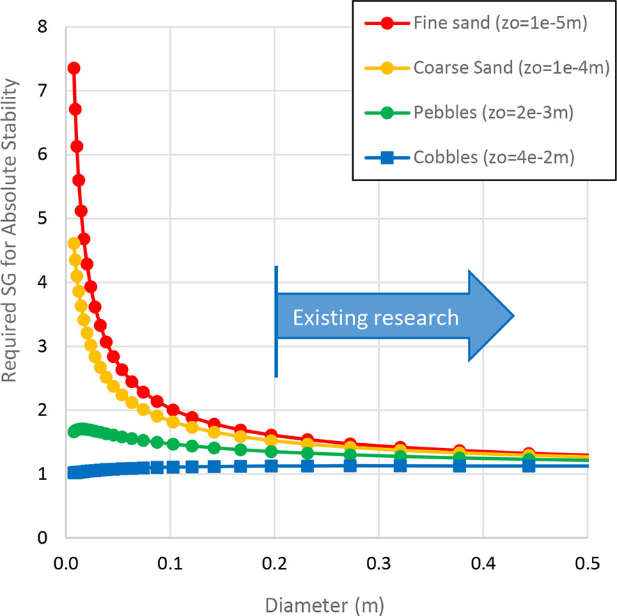
Figure 1 Inverse relationship between required SG and D versus seabed roughness under steady current conditions following F109 (DNV, 2021a) Equation 3.1. The plot shows the general trend that the required SG for stability tends to infinity as diameter gets small, with the existing design guidance for on-bottom stability based on hydrodynamic research using pipes greater than 0.2 m in diameter.
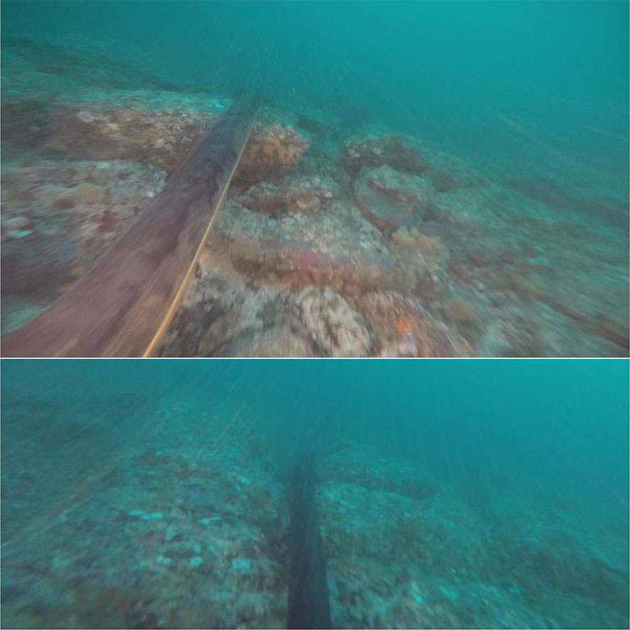
Figure 2 Example images of power cables on rocky seabeds (Images courtesy Simec Atlantis, Griffiths et al., 2018b) showing the subsea power export cables from the MeyGen tidal stream energy project. Key features to be observed are the size/scale of the rocky boulders/outceops compared to the diameter of the cable and the resulting wedging of the cable into crevices at the points of contact between cable and seabed, between which the cable is in span above the seabed.
In each of the above scenarios, the conventional published design methods (typically DNV) yield results which are extremely onerous for cable on-bottom stability and allowable spanning.
For completeness, the requirements of a number of alternative design standards and recommended practices have been reviewed for their guidance on what designers should do to address cable on-bottom stability. In summary:
● DNV-ST-O359 (DNV, 2021b) Subsea power cables for wind power plants defines on-bottom stability as the ability of a subsea power cable to remain in position under lateral displacement forces due to the action of hydrodynamic loads. This design standard requires the on-bottom stability to be addressed as part of detailed design if applicable (Clause 2.3.2) as well as protection against movement during installation between laying and subsequent protection (Clause 2.3.4). No guidance is offered on how the designer should achieve this requirement, and no reference is provided to F109.
● DNV-RP-O360 (DNV, 2021c) Subsea power cables in shallow water contains the same definition of stability above but further clarifies in Clause 3.3.6 that currents may affect the stability of cables lying unprotected on the seabed. The recommended practice also states that where the cables are unburied, the on-bottom stability of appurtenances including tubular products (e.g. ductile iron shells), mattresses and bags, as well as rock placement. No guidance is offered to the designer on how this stability is to be achieved, other than for the stability of rock berms.
● ISO 13628-5 (ISO, 2021) Petroleum and natural gas industries – Design and operation of subsea production systems Part 5: Subsea umbilicals advises that as part of “load effects analysis” the displacement due to on-bottom stability from functional and environmental loads may be required. The standard states that “DNV RP-F109 is an example of a standard suitable for assessing the lateral stability of umbilicals exposed to current and wave loading.”
The context is therefore noted that whilst subsea cables are required to have adequate on-bottom stability by a number of leading design standards, none of the standard industry design codes for seabed cables or umbilicals mandate the use of the F109, and for subsea power cables no guidance is offered on how to design the cables to be stable.
2 Safety philosophy and reliability
2.1 Philosophy
The potential failure of cables and umbilicals due to on-bottom instability has minimal environmental, health or safety impact. There are consequences such as a loss of power transmission or in the case of an umbilical the triggering of an automatic well shut-in. However, the failure of a hydrocarbon pipeline has far more dramatic and significant consequences, which can have major human and environmental impact, as illustrated in Figure 3.
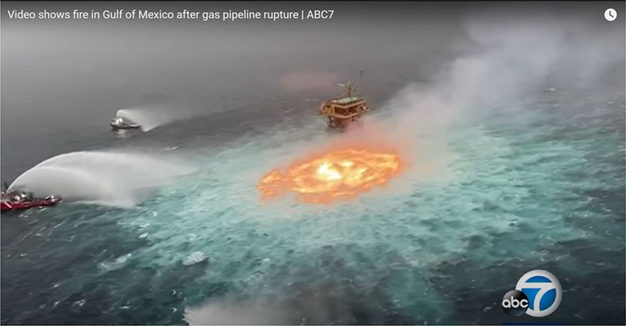
Figure 3 Health, safety and environmental consequences of hydrocarbon pipeline failure (ABC7, 2021). The video shows a sea-surface fire resulting from a hydrocarbon gas release from a subsea pipeline in close proximity to a platform, representing a potentially catastrophic safety risk to any personnel on the platform and potentially significant environmental consequences for the marine environment due to pollution.
The uncertainty analysis undertaken by DNV that underpins the factor of safety presented in Section 4.5.3 of F109 is intended to address the risks of hydrocarbon pipeline failure leading to loss of containment, rather than umbilicals or cables. F109 recommends for umbilicals and cables that the factor of safety be agreed on a project-by-project basis. The major consequences of umbilical and cable failure are therefore anticipated to be financial, including repair of the damage, any remedial stabilization, and the consequential loss of production and associated non-supply commercial costs.
The over-arching context therefore leads to a fundamental question –
Should humanity set out to build tens of thousands of new uncrewed unexplosive relatively simple and standardized offshore structures using practices which have largely been developed many decades ago to suit a few hundred bespoke-designed highly complex crewed but potentially highly explosive and environmentally-catastrophic structures?
Set in that context, the sensible answer appears to be “Probably not!”.
2.2 Industry background on reliability modelling of on-bottom stability
The approach of adopting a reliability-based design methodology has been investigated and incorporated into the subsea pipeline industry through the SUPERB project (Sotberg et al., 1996) which was undertaken in the late 1990s. The then-new reliability-based design approach has been embedded across the spectrum of subsea pipeline design aspects and incorporated into all of the guidance documents, superseding the previous approach, which was based on the application of deterministic parameter values and a codified margin to allow for ‘safety’.
However, in practice the application of reliability-based design to subsea pipeline on-bottom stability has been subject to much less widespread scrutiny or challenge. A summary of the identified peer-reviewed published literature on stability reliability design is presented in Table 1 (except for the DNV report regarding factors of safety included in F109 which remains unpublished). Of these works, only the stability design rationale articulated by Tornes et al. (2009) provides a direct link between the on-bottom stability response of a subsea pipeline, and limit states which constitute outcomes involving a loss of containment of the hydrocarbon contents of the pipeline. These are expressed through the DNV concepts of Fatigue Limit State (FLS), Ultimate Limit State (ULS) and Accidental Limit State (ALS) but which translate into rupture of the pipe wall resulting from fracture of the steel due to fatigue, excessive bending or local buckling of the pipe.
Table 1 Summary of the present literature regarding reliability design approaches to subsea pipeline on-bottom stability.
2.3 What are the ‘real’ limit states for subsea cables and umbilicals?
The new British Standard for on-bottom stability of subsea cables on rocky seabeds (BSI, 2023) gives the on-bottom stability limit states as:
1. Excessive bending or tension in the cable resulting in mechanical failure which exceeds the manufacturer’s allowable envelope for operational or installation conditions, as relevant.
2. Fatigue failure of an element of the cable (e.g. armour wire, insulation or conductor core) due to excessive cyclic bending and/or tensile strains imposed on any point of the cable.
3. Excessive damage to outer layers of the cable incurred by relative movement against the seabed surface which may compromise the strength required for retrieval or in service integrity, expose components, and potentially changes cable behaviour in the affected section leading to excessive movement and subsequent mechanical or electrical failure.
4. Excessive local contact force.
5. Excessive impact force or repetitive impact damage.
It is therefore considered that the Net Present Value (NPV) of possible failure and repair costs should form the basis of the reliability and integrity philosophy. This approach must also account for the limit states and uncertainties intrinsic in the COREstab and STABLEpipe methods, which require careful consideration of the relevant real behaviour of cables on rocky and sandy seabeds, respectively. It is proposed that projects should adopt the above limit states as those which are used to determine the acceptance limits on the design to achieve the required levels of reliability driven by the NPV assessment of cable or umbilical failure.
An enormous variety of array and export cable layouts have been constructed, resembling the collective outcomes of many rainy-days of playing ‘Pipopipette’ (also known as ‘dots and boxes’ or ‘paddocks’, Édouard, 1895) as shown in Figure 4 – however the detailed arrangement of each development is assumed to follow logical and optimised methods as described (for example) by Pillai et al. (2014) and Fischetti and Pisinger (2018). The outcome is that unequal volumes of power are anticipated to flow between each individual array cable connection, with the consequence that the individual risk and consequence of failure for each cable is not uniform. This represents a fundamental difference with hydrocarbon pipelines, where any loss of containment anywhere in the system guarantees front-page infamy for the operator concerned (see Figure 3).
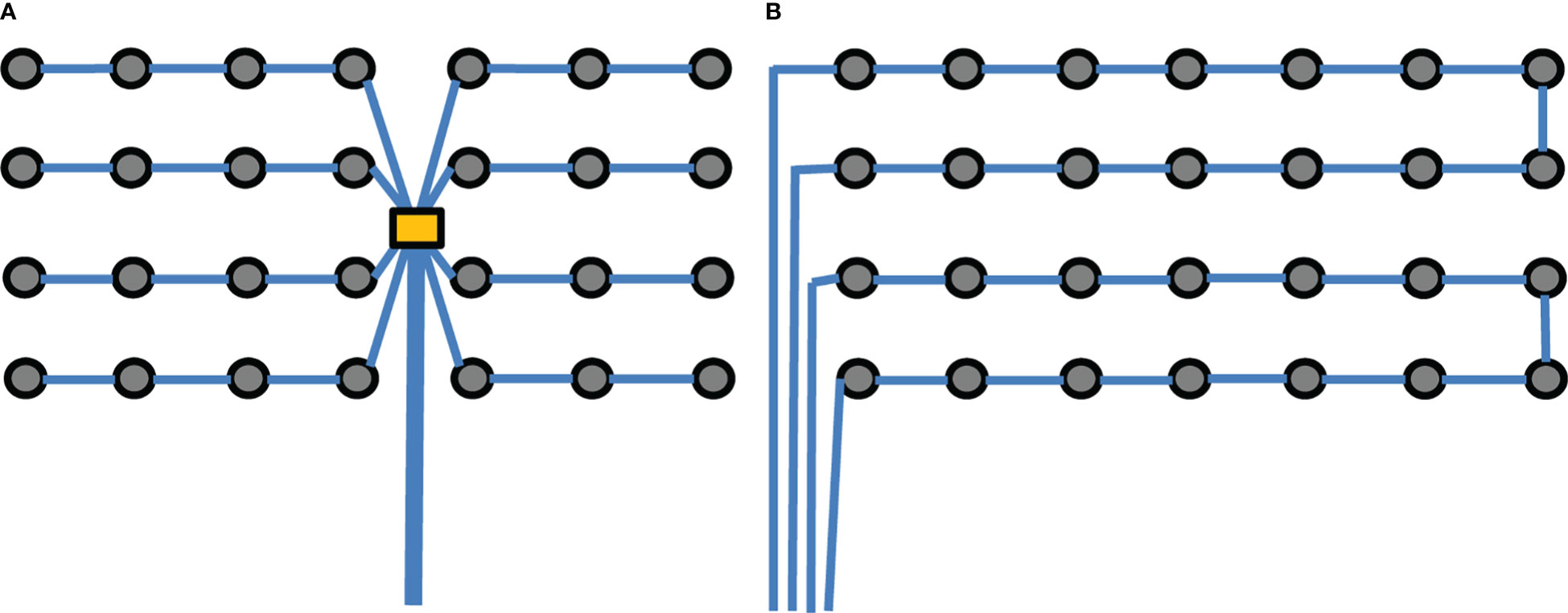
Figure 4 Example OWF cable layouts including (A) ‘spider’ and (B) ‘loop’ designs. The different cable layouts demonstrate very different levels of risk to any individual cable segment, with both arrangements having lower consequences of failure (in terms of lost power) for segments further from the export cables, whilst the export cables each have the highest levels of failure consequence. The ‘spider’ arrangement has higher risk than the ‘loop’ arrangement due to increased redundancy.
2.4 10-6 and all that: What do failure probabilities really mean?
As a cautionary note, it is reminded that the essential requirement of a reliability-based design approach is not the exhaustive analysis of enormous numbers of numerical simulations of uncertain parameters against some form of potential failure limit state (as appears to be the case in many of the papers in Table 1).
Instead, as stated by Sotberg et al. (1996) “the performance of offshore pipelines is subjected to uncertainties in the physical quantities and models governing the structural behaviour. Application of reliability methods guided by engineering judgement and experience is thus a rational way to include the effect of these uncertainties in the final design assessment.”
This quote has two critical elements relevant to this discussion. Firstly, it acknowledges that uncertainties exist in models as well as the input parameters; this uncertainty cannot be quantified by running a single model repeatedly with different inputs. Secondly, it recognises the application of judgement and experience, which is key to recognizing when conventional models may be inappropriate.
The design of cables on rocky seabeds introduces both of these critical elements, because it involves stepping outside of the bounds of collective knowledge of the offshore oil and gas industry and exploring accumulated knowledge from a broader context to find more appropriate models of behaviour. Such experience includes the published lessons learnt and observations of cable failures and damage such as the example shown in Figure 5 at the European Marine Energy Centre (EMEC) renewable energy site in the UK, which is from the review published by The Crown Estate (2015). Other cable incidents have been collated by Conférence Internationale des Grands Réseaux Électriques (CIGRE).
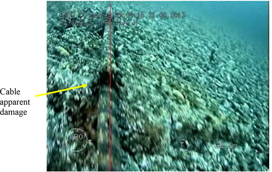
Figure 5 Cable damage example: reported case of abrasion due to strumming which may occur due to cable lateral sliding under wave and/or current loading (The Crown Estate, 2015).
Similarly, the late great Prof. Andrew Palmer (2012) expressed significant reservations about the 10-6 target failure probabilities and whether these were grounded in reality or were ‘nominal’. DNV responded to these challenges (Agrell and Collberg, 2014) to explain that “although these numbers provide a strong tool for evaluating the ‘robustness’ of a design, it is not straightforward to see how they relate to the probability that a given pipeline will fail. Moreover, as the definition of nominal probability in design codes is not very clear, it might mislead the end user to interpret this as an actual failure frequency. Such concerns are by no means confined to risk-based design of pipelines, but are also a continuing debate within risk analysis in general”.
Hence, in order for the on-bottom stability design of a given cable or umbilical to achieve the low level of failure risk which is warranted based on the (anticipated) high consequential cost of failure, the design approach needs to carefully navigate between ‘nominal’ and real probabilities of exceeding the (very real) limit states which govern the failure modes of subsea cables and umbilicals. To do this we must avoid blind direct adoption of ‘nominal’ failure targets from subsea hydrocarbon contexts which may be (or more likely are not) relevant.
3 State-of-the-art subsea cable stability design methods on rock: COREstab
3.1 Industry examples and context for rocky seabeds
A number of marine renewable energy projects around the world have been either proposed or actually developed where they have been located in areas where shallow water depths and strong currents and/or large and persistent wave action means the seabed has been swept clear of sediment. For example, a high number of installed wave and tidal facilities have required cable stabilisation measures (Sharkey, 2013) such as armour casings and concrete mattresses (at the EMEC site, off the Scottish coast), rock dumping (at the Wavehub site off the Cornish coast) and horizontal directional drilling (the Marine Current Turbines SeaGen project in Strangford Lough, Northern Ireland). Examples of cables installed over rocky seabeds can also be found at the tidal energy sites in the Bay of Fundy that feature medium to coarse gravel and cobbles (Stark et al., 2013), including potentially mobile gravel dunes. Rocky seabeds also occur on the Australian continental shelf along hydrocarbon pipeline and cable routes, including relatively flat limestone pavements and calcarenite caprock, as described by Sims et al. (2004) and Duncan and Gavrilov (2012).
The marginal commercial viability of renewable energy projects means that they are still trying to reduce costs while competing with other projects in less demanding locations. The prevailing design methodology (The Crown Estate, 2015) used to evaluate the on-bottom stability of pipelines and cables on rocky seabed for the marine renewable energy industry is F109 (DNV, 2021a), which was originally written for the offshore oil and gas industry for hydrocarbon-containing pipelines. This recommended practice features three different approaches to stability design, which compare the actions on the pipe/cable, including pipe weight, hydrodynamic loading and geotechnical seabed restraint. Conventional cable stabilisation designs and methods are simply too costly for these projects to be viable. Hence there is a strong appetite by these projects to identity where existing design methods can be radically re-engineered to capture additional relevant physics and better understand the real behaviour of cables under these conditions.
It has been recognised that on rocky seabeds the local profile of the seabed surface, at length scales comparable to the cable diameter, can have a very significant influence on the behaviour of subsea pipes and umbilicals, as demonstrated by the MeyGen cables shown in Figure 2. Where the rugosity of the seabed includes length scales of a similar order of size as the cable diameter, both the lateral resistance and hydrodynamic forces are dramatically altered, as documented by Griffiths et al. (2018b); Griffiths et al., (2018c). In order to correctly predict the behaviour of seabed cables, it is necessary to be able to model the meso-scale roughness elements which are often too small to be resolved by conventional MBES survey methods.
3.2 COREstab method development
The COREstab (Cables On Rock Enhanced stability) approach has been developed to address these considerations and has been described in Griffiths et al. (2018b); Griffiths et al. (2018c) and Griffiths (2022). The meso-scale approach consists of four steps:
1. Analyse the video records of the seabed survey to extract and statistically characterize the roughness elements present.
2. Use the measured statistical properties of the meso-scale seabed elements, randomly generate a synthetic blanket of roughness elements as shown in Figure 6 to simulate the seabed profile, matching the size shape and orientation of the observed seabed roughness features with the synthetic roughness stochastic features also plotted in Figure 7 for comparison with the measured values. As this process represents a random representation of the seabed profile, following the guidance in F109 for Dynamic stability analysis, at least 7 random simulations are analysed.
3. Drape this synthetic blanket over the MBES macro-scale seabed bathymetry profile to produce a composite seabed at a scale which is small compared to the cable diameter.
4. Lay the cable down onto the composite seabed profiles. By laterally sliding the umbilical by a nominal distance of 10D each way, the lateral resistance of the cable can be calculated from the micro-scale interface friction coefficient and the methods documented by Griffiths et al. (2018c). This distance is chosen for two reasons. Firstly, because it is consistent with the maximum lateral displacement adopted in conventional dynamic pipeline stability analysis (e.g. DNV 2021), and secondly because it is sufficient distance relative to the seabed roughness wavelength for representative average values of the lateral resistance to be found. Based on the local gappiness and seabed profile, the hydrodynamic forces on the cable can also be calculated following the methods described in Griffiths et al. (2018b). The on-bottom stability factor of safety can then be found by applying the F109 Absolute stability calculation method, accounting for the increase in lateral resistance and reduction in hydrodynamic forces. Note that the adoption of 10D here is arbitrary in order to get a reasonable indication of the natural fixation points along and across the cable route.
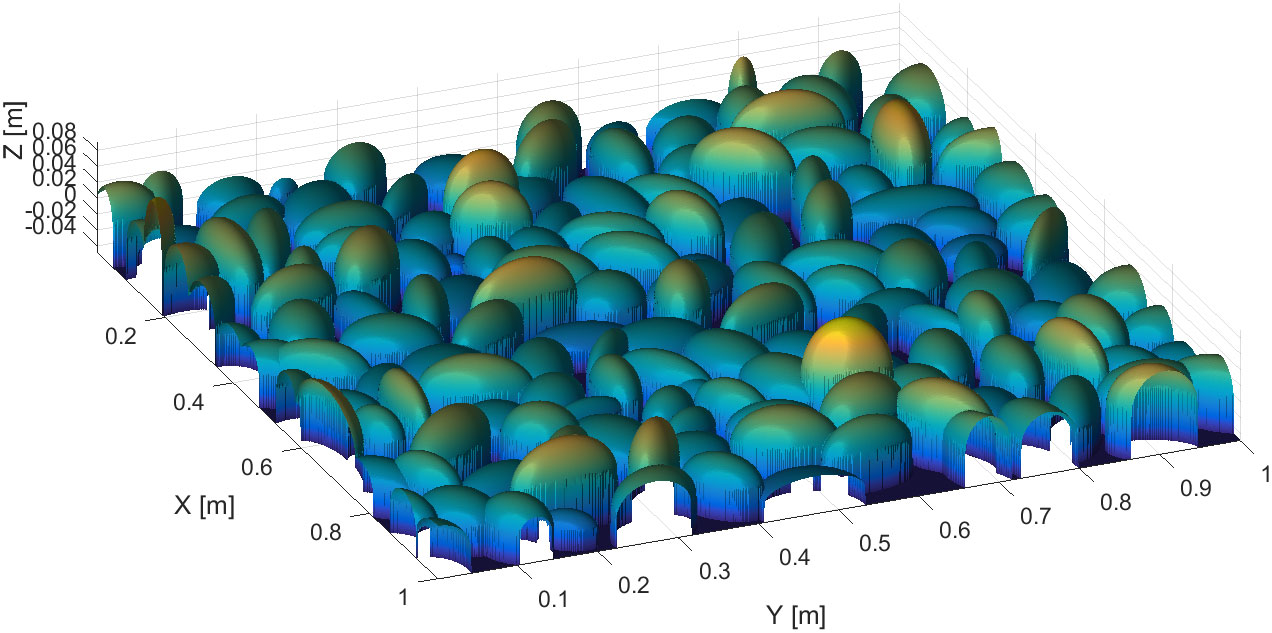
Figure 6 Example Tetris-packed synthetic rock blanket produced to represent the meso-scale roughness of the rocky seabed located within the MeyGen tidal stream energy project (Griffiths et al., 2018a). Colours represent shading/rendered illumination.
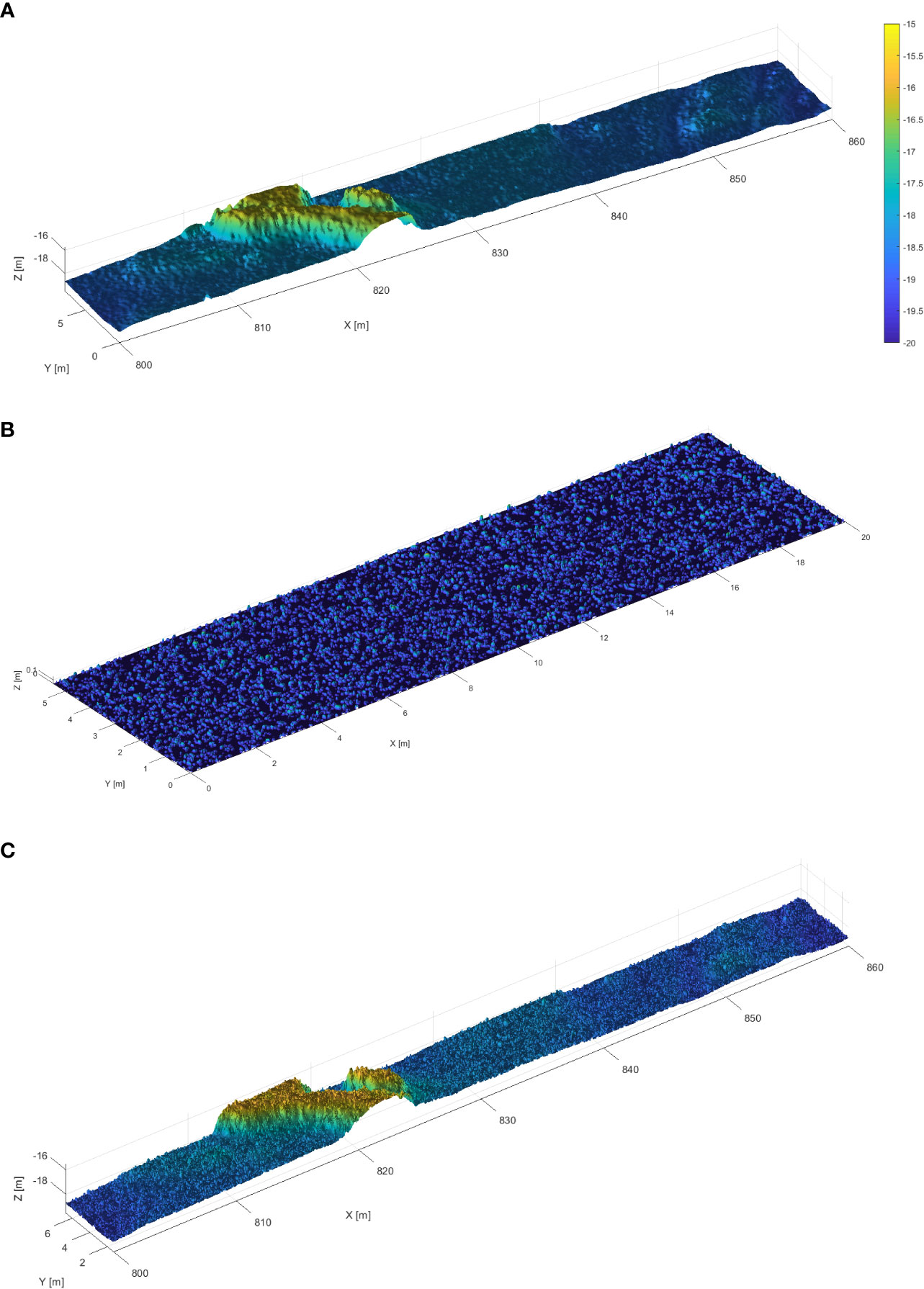
Figure 7 Illustration of (A) macro scale, (B) meso scale and (C) composite seabed sections.
3.3 New industry guidance
The COREstab design approach is presently being drafted into a new British Standards Institute guideline for the on-bottom stability of cables on rocky seabeds. This guideline is presently available for public review.
3.4 Project worked example 1: cables on rocky seabeds: meygen tidal stream energy
The new COREstab models and approaches to predicting the on-bottom stability of seabed cables have been used to back-analyse the stability of the subsea cables that MeyGen installed for Phase 1A of the Pentland Firth Inner Sound tidal stream energy project as published by Griffiths et al. (2018b).
These cables are located on rocky seabeds in an area where severe metocean conditions occur. The MeyGen Phase 1A project represents the first stage of the UK’s commercial-scale tidal stream energy project. MeyGen has been awarded a Crown Estate lease for the option to develop a tidal stream project of up to 398 MW in the Inner Sound between Scotland’s northernmost coast and the island of Stroma within the Pentland Firth. The initial phase of the project consists of four 1.5 MW horizontal axis turbines each with a dedicated power export cable supplied by JDR Cable Systems and routed approximately 2 km south to the Scottish mainland. The subsea cable installation and commissioning was undertaken in September 2015. Since the turbines were installed in 2017, total power production has now surpassed 37 GWh (Simec Atlantis, 2020).
The cables were analysed during the design phase using conventional F109 stability analysis methods and shown to be unstable, however the project decided on the balance of risks to install the cables without secondary stabilization. Since installation, repeated ROV field observation of these cables shows them to be stable on the seabed with little or no movement occurring over almost all of the cable routes, despite conventional engineering methods predicting significant dynamic movement.
The back-analysis by Griffiths et al. (2018b) was undertaken retrospectively, after several years’ operation of the cables. This analysis shows that the loads and lateral resistance are modelled in an over-conservative way by conventional pipeline engineering techniques and was able to explain why the cables were actually stable, despite predictions to the contrary using F109. The COREstab design method involves developing a much more relevant model of the seabed features that are similar in size to the diameter of the cable. It was found that by capturing the meso-scale seabed roughness which resulted in over 99% of the cables being suspended above the seabed in a profusion of small spans such that:
1. Vertical hydrodynamic lift forces were reduced by over 90%.
2. Horizontal hydrodynamic forces were reduced by around 30%.
3. Due to the enhanced lateral resistance of cable interaction with meso-scale seabed roughness the lateral resistance to movement was increased on average by over 70%.
Overall, our analysis highlights that current on-bottom stability design methods can be unnecessarily conservative on rocky seabeds. The dramatic contrast is between the predictions by F109 that the required SG for stability was around 14 – between the density of solid lead (SG = 11.3) and solid gold (SG = 19.3). In contrast Griffiths et al. (2018d) showed that using the COREstab method the cables (with actual SG = 3.34) were stable with a “factor of safety” of between 3.1 and 5.1. Whilst the COREstab method was only retrospectively applied to the MeyGen cables, it is understood that the project avoided over £1M in costs by deciding not to install secondary stabilization.
4 State-of-the-art subsea cable stability design methods on sand/silt: STABLEpipe
4.1 Stable pipelines on an unstable seabed
It was shown many decades ago by the late Prof. Palmer that sandy seabeds become mobile well before the on-bottom stability limit for subsea pipelines is reached (Palmer, 1996), leading to scour and sedimentation which profoundly alters the seabed profile and condition of the pipe. While this is acknowledged in F109 Section 8.5, F109 does not provide any useful design method guidance but instead refers to Griffiths et al. (2018d). This reference describes the extensive research program which has been completed through the STABLEpipe JIP, using the UWA recirculating O-tube (Cheng et al., 2014) as a transformational research tool in the development of a new design guideline which has now been co-developed with DNV using the design methods described by Draper et al. (2018a); Draper et al. (2018b). The STABLEpipe guideline has been used on a number of projects and remains the most thorough DNV-endorsed description on how to design pipelines on erodible seabeds
The fundamental change from conventional design is to recognize that there exists a tripartite interaction between the umbilical (or pipe), soil and the fluid loading which means each element influences the other, as illustrated in Figure 8.
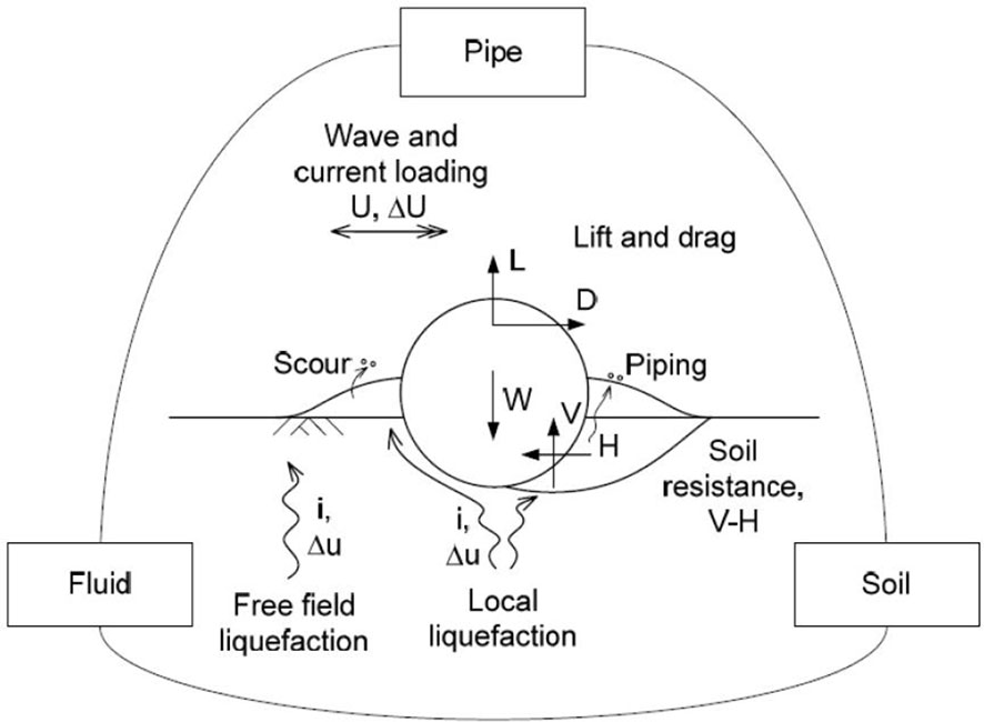
Figure 8 Tripartite interaction between umbilical, soil and fluid (Griffiths et al., 2018d). The diagram illustrates that the response of a pipe or cable on a sandy erodible seabed cannot be correctly understood without capturing each element of the interactions between pipe and fluid (hydrodynamic forces as well as flow amplifications around the pipe), pipe and soil (lateral and vertical resistance, as well as contributing to liquefaction) and soil and fluid (scour, erosion, sedimentation and liquefaction).
4.2 STABLEpipe method development
In early 2008, Woodside initiated a research program with the University of Western Australia with an aim to establish an O-tube flume facility as shown in Figure 9 that is capable of modeling the tripartite pipe-soil-fluid interaction at approximately 1:1 scale for cables (Figure 8). This design of flume allows a model pipeline to be subjected to near-seabed flow conditions, such that wave-induced liquefaction and local scour may evolve naturally, concurrent with hydrodynamic loading of the pipeline and the mobilization of soil resistance. The O-tube project was also supported by a grant from the Australian Research Council (ARC) under the ARC Linkage Projects Program (2009) and the resulting facility is described in more detail by An et al. (2011).
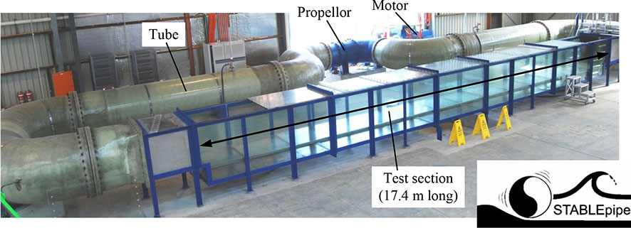
Figure 9 UWA O-tube flume and the STABLEpipe JIP logo (Griffiths et al., 2018d). The main test section is 17 m long with the fluid zone being 1 m wide by 1 m high, and the soil zone being around 0.4 m deep. The flow in the test section is rectilinear representing both wave and current motions over the bottom meter of the ocean. The facility is remarkable in that any sediment lost downstream out of the test section is transported around through the pump and returns to nourish the upstream mobile seabed. Steady currents up to 3 m/s and waves of 2.5 m/s velocity with a period of 15 s are feasible.
It was expected that the insights from successful O-tube tests would allow the understanding of pipe-soil-fluid interaction to be updated and refined. When distilled into revised analysis procedures, these advances might produce CAPEX savings on new projects in the order of tens of millions of dollars per project by reducing the extent of secondary stabilization and/or the degree of primary stabilisation. Another motivation for Woodside and UWA initiating this project was to enable the ongoing stability of the existing 40-in North Rankine trunkline to be proven, so as to support the life extension of that facility, as reported by Jas et al. (2012).
Also in early 2008, JP Kenny (now Wood Plc.) initiated Phase 1 of the STABLEpipe JIP, looking at value definition. The project name comes from “STAbility of on-Bottom pipeLines under Extreme conditions Joint Industry Project”. Phase 1 of the STABLEpipe JIP had the primary goal of improving industry understanding and engineering design practices in relation to offshore pipeline stabilisation in challenging environments.
Among the outputs of Phase 1 were studies that identified the potential benefit from further definition of each aspect of on-bottom stability design. Based on these outputs, the participants and sponsors agreed to undertake a range of research programmes to tackle these critical knowledge gaps, including large scale testing (as had been initiated by Woodside and UWA), engineering studies and field monitoring if future funding permitted. At the end of Phase 1 of the JIP, Woodside proposed to lead Phase 2 of the JIP. By including the existing Woodside-UWA O-tube project in Phase 2 of the STABLEpipe JIP, with Chevron as a co-sponsor, additional scopes of work were possible, to the mutual benefit of all participants.
Extra leverage was created through parallel research funded by the ARC, the LRF and Shell, who supported academics and PhD students at UWA over the same period, working on related activities, with the outcomes feeding into STABLEpipe.
The aim of the STABLEpipe JIP was to assist the development of practical and locally-applicable stabilisation solutions that will provide operators with methodologies and cost-saving approaches to economically develop prospects in the NWS – of which there were many being pursued at that time. A key goal of the JIP participants was to produce a readily usable and clearly articulated design guideline: this was achieved, with the guideline being co-developed and published by DNVGL (2017). In this respect STABLEpipe was a mechanism to bring together operators, engineering organisations, industry experts and research professionals to deliver cost effective high integrity stabilisation solutions.
The outcomes of the STABLEpipe JIP together with the design methods have been described in the literature as follows:
1. A review of the broad industry research effort over the last decade (of which STABLEpipe JIP research is just one part) to improve our ability to model the on-bottom stability and behavior of subsea pipelines, as summarized by Griffiths et al. (2018d).
2. An understanding of the fundamental influence of the evolution of storms on the stability outcomes, by Draper et al. (2015).
3. An illustration of practical methods for modelling changes to submarine pipeline embedment and stability due to pipeline scour (Draper et al., 2018a).
4. An investigation of the influence of fine-grained soils and variable metocean conditions described by Draper et al. (2018b).
5. An investigation of the influence of shallow mobile sediment layers on the evolution of scour as described by Draper et al. (2014).
The predictions of the STABLEpipe method have been validated by back analysis against field observations of existing subsea pipelines, for which significant post-lay morphodynamic processes were observed to occur through routine integrity surveys over their lifetime:
1. The cable/pipe remaining at approximately the same elevation with respect to the far-field seabed, but experiencing significant local sedimentation as described by Leckie et al. (2016).
2. The cable/pipe experiencing significant lowering compared to the far-field seabed with a significant proportion of the pipe/cable remaining in span above the scoured trench and only small localised sections of pipe/cable touching the seabed as described by Leckie et al. (2015).
Each of these scenarios represent an improved outcome with respect to the on-bottom stability compared to the as-installed condition, as discussed by Leckie et al. (2018).
The key design and analysis steps are set out in detail in Draper et al. (2018a) and summarized in Figure 10 with the key elements being to:
1. Predict the initial embedment of the cable and establish the likely distribution of initial spans present as pre-existing spans which may form the initiation points for scour progression.
2. Model the evolution of metocean conditions as illustrated in Figure 11.
3. Predict the evolution of seabed morphodynamics around the cable, through the process of spans lengthening and deepening due to sediment transport, leading to either pipe sagging at the mid-span until touchdown occurs onto the bottom of the scour hole, or the shoulders of the span collapse again leading to increased pipe embedment compared to the far field.
4. Check the stability of the pipe through each timestep in this simulation.
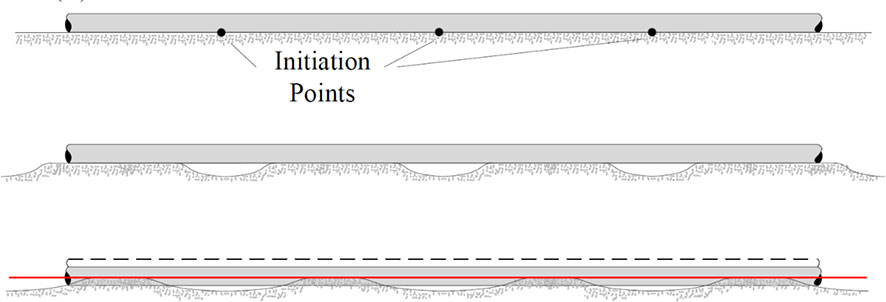
Figure 10 Scour initiation, span growth and umbilical sinking for ‘close’ initiation points (Draper et al., 2018a). The plot shows the evolution of seabed morphodynamics from the initiation of scour at points along the pipe followed by longitudinal and vertical deepening of the scour span through to bearing collapse of the span shoulders leading to enhanced far-field embedment of the pipe.
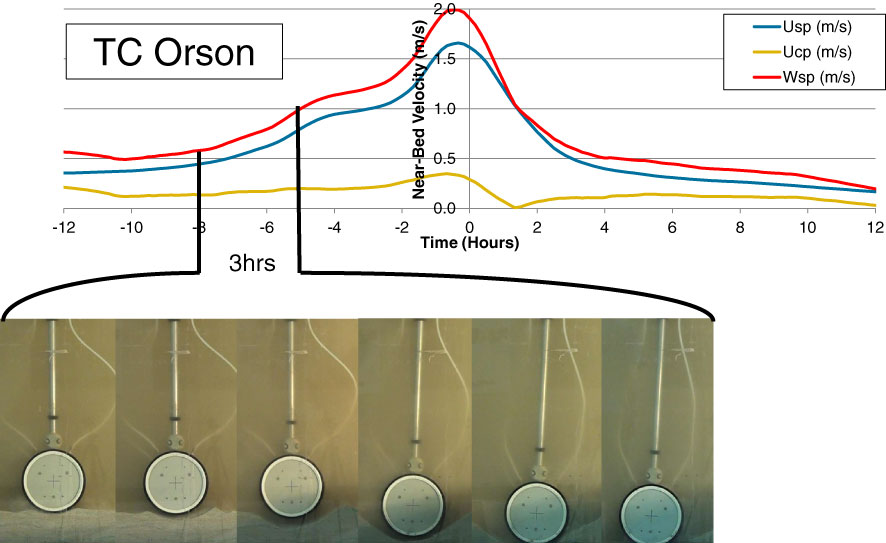
Figure 11 Storm evolution over time, showing active morphodynamics well before storm peak (Griffiths et al., 2018d). The major epoch of active scour and lowering of the pipe in this example storm occurs between 8 and 5 hours prior to the peak of the cyclone, resulting in the pipe lowering so very substantially into the seabed compared to its initial as-laid embedment. The conventional F109 design approach of evaluating the stability at the peak of the storm using the as-laid embedment is therefore profoundly irrelevant.
4.3 STABLEpipe relevance to cables
The STABLEpipe method was originally developed to aid in the stability design of subsea hydrocarbon pipelines – especially the large and relatively light gas export trunklines used to export gas from offshore production facilities to shore. However a number of aspects of seabed cables mean that the STABLEpipe design method is particularly effective and relevant, including:
1. Cables associated with OWF projects are frequently placed on shallow sand banks and in areas where the seabed is mobile.
2. These locations frequently feature ripples and megaripples which provide highly reliable initiation points for onset of scour and the orphodynamics processes which are modelled by the STABLEpipe method.
3. The volume of seabed soil requiring to be scoured for a cable is extremely small – with the horizontal scour rate equation featuring a 1/D term which accelerates the scour processes. When this is combined with the much smaller Lcr typical of cables, the STABLEpipe method works profoundly well to capture benefits to the on-bottom stability of cables.
Given the severity of the metocean conditions found across many shallow-water OWF and other marine renewable energy project sites and that sections of the surficial seabed soil may be sandy, the likelihood is that enhanced on-bottom stability will be achieved with the application of design methods incorporating sediment transport and scour. While these methods extend beyond F109 Section 8.5, they have been applied to multiple projects, with Woodside providing feedback to shareholders on the savings they achieved on just the first project it was applied to (Woodside Energy, 2012).
A key question which arises in most laboratory testing is how model tests can be adequately scaled to prototype conditions to correctly account for the fact that many properties (e.g. hydrodynamic forces and sediment transport and scour rates) physically scale with contradictory relationships (Le Mehaute, 1976; Hughes, 1993). The interesting observation is that the majority of testing undertaken in UWA’s Large O-tube for the STABLEpipe JIP used a model pipe which was 200 mm in diameter, as shown in Figure 12. This results in a model:prototype scale of approximately one (1:1) for many subsea power cables used in the offshore wind industry. It is therefore clear that the results of this testing are of direct relevance, without any scaling, to predicting the behavior of subsea cables on sandy erodible seabeds.
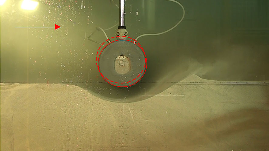
Figure 12 “Scale” model testing in UWA Large O-tube of gas trunklines using 200mm OD pipe is actually 1:1 scale testing for subsea cables. As per the STABLEpipe design method it is easy to show that the volume of soil needing to be mobilized to result in more than 50% lowering of a cable into the seabed can be achieved (and was frequently observed in UWA Large O-tube tests to occur) in about 10 minutes. It is therefore very much easier for a cable to be come self stable than (for example) a large-diameter gas trunkline.
4.4 Project worked example 2: cables on soft sandy/silty seabeds
The STABLEpipe design method was applied to the on-bottom stability design of the array and export cables for an OWF located in Asian waters. The water depth varied from zero at the shore crossing to around 30 m in the field, with the stability analysis addressing the temporary condition where the cables were laid on the seabed prior to being trenched for lifetime protection and stabilization. The project site is in an area prone to experiencing a number of tropical revolving storms (Cyclones/Typhoons/Hurricanes) each year. In terms of project drivers, improvements in the predicted stability of the cables had the potential to increase the allowable time (and risk of storms occurring) between the cable lay and trenching operations.
The results of the on-bottom stability analysis considered the potential for beneficial increases in cable embedment during the build-up phases of possible storms, with the results of these assessments being compared against the predictions using just the conventional un-modified F109 design approaches. The results of this comparison in stability design methods is presented in Figure 13, showing a scatter-plot of the relative stability ranking of each cable segment. This plot clearly shows no correlation between the predictions of cable-focused stability design methods and the results of using F109. This lack of correlation flags very significant concern regarding the validity of using an un-modified generalized subsea pipeline design guideline on subsea cables – most especially given its almost ubiquitous utilization in the offshore renewables industry.
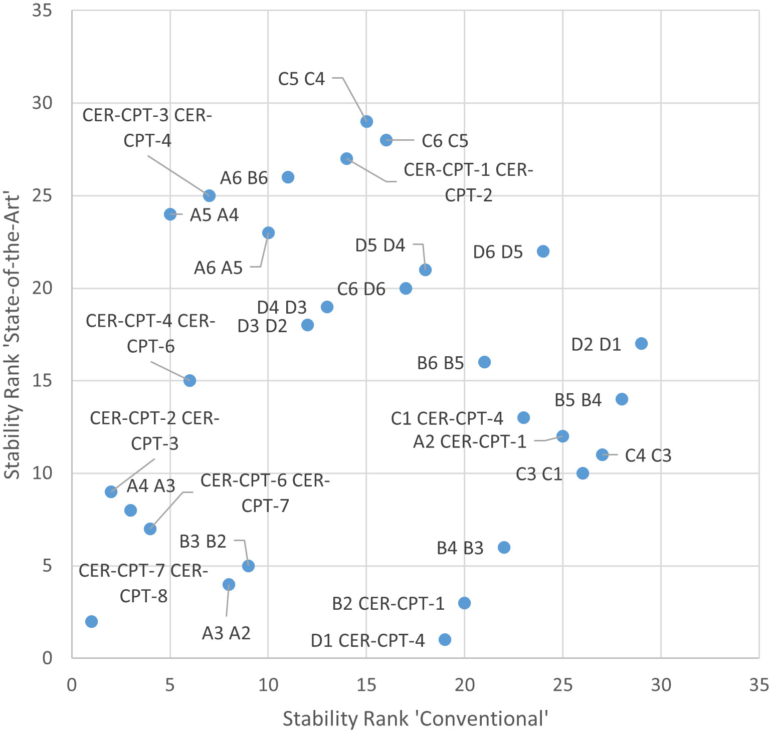
Figure 13 Ranking of cable routes by relative stability: conventional F109 rank versus ‘state-of-the-art’ methods, which demonstrates no discernable correlation whatsoever. The point of this plot was to assist the project team in determining the priority for cable trenching sequence to ensure as low as possible a risk of instability. It was found that the ranking of stability using conventional versus cable-optimized STABLEpipe design approaches resulted in such a low correlation that the reliability of the cables if assessed using the conventional approach might be severely compromised.
5 Conclusions
The proposition has been put forward that the offshore renewables industry should take great care in deciding whether or not to adopt existing oil and gas industry design recommended practices and guidelines, or whether to develop bespoke design guidance. New bespoke guidance can begin with fresh assumptions regarding (i) the consequences of failure, (ii) the failure modes, (iii) the target reliability and (iv) the engineering system behaviour relevant to ORE infrastructure.
This proposition has been explored by studying the applicability of existing industry guidance for the on-bottom stability of subsea cables. The study has considered the case of cables on rocky seabeds, and the contrasting case of cables on mobile sandy seabeds. These case studies have demonstrated profound differences between the design outcomes using conventional F109 design methods – evolved through oil and gas experience – compared to the more relevant and applicable response predictions when using the COREstab design method for cables on rock and STABLEpipe for cables on sand.
Considering the results of these case studies and the underlying physical differences between subsea cables and conventional oil and gas pipelines, it is concluded that for cable on-bottom stability design bespoke design approaches for offshore renewables are clearly warranted. This conclusion is supported by the successful experience applying these design methods to over 9.1 GW of new offshore wind projects globally.
As the offshore wind industry and other ORE sectors continue to mature and evolve, we encourage the industry to remain open and proactive in seeking design guidance that is tailored to ORE, in order to best support the rapid energy transition to net zero, to mitigate the climate crisis.
Data availability statement
The original contributions presented in the study are included in the article/supplementary material. Further inquiries can be directed to the corresponding author.
Author contributions
TG drafted the majority of this work, which draws together ideas and concepts from a broad body of research work including prior publications by the co-authors. The remaining authors contributed significantly to the underlying research and industry case studies as well as the editorial evolution and refinement of the paper. All authors contributed to the article and approved the submitted version.
Funding
DC acknowledges the financial support of the Tidal Stream Industry Energiser project (TIGER), which is co-financed by the European Regional Development Fund through the Interreg France (Channel) England Programme. TG acknowledges the financial support of an Australian Government Research Training Program (RTP) Scholarship, UWA Safety-net Top-up, STABLEpipe scholarship and Small Diameter Pipeline scholarships, as well as support from a University Club of Western Australia Research Travel Scholarship. SD acknowledges the financial support of The Lloyd’s Register Foundation. Lloyd’s Register Foundation supports the advancement of engineering related education, and funds research and development that enhances safety of life at sea, on land and in the air. DW acknowledges the support of the UK EPSRC Offshore Renewable Energy Supergen Hub, grant ref. EP/S000747/1. YT acknowledges support from the National Natural Science Foundation of China (Grant No. 51479025). The authors gratefully acknowledge the support of the Australian Research Council (ARC) and Woodside Energy Ltd. for elements of the work reported in this paper through ARC Linkage Project LP150100249 Hydrodynamic forces on small diameter pipelines laid on natural seabed, with participation by The University of Western Australia and University of Western Sydney. http://purl.org/auresearch/grants/arc/LP150100249. The authors gratefully acknowledge the support of the STABLEpipe JIP Sponsors, Woodside and Chevron who have enabled the STABLEpipe research work to be undertaken and published, and therefore made available for uptake by industry as well as scrutiny and improvement by researchers and practitioners. Elements of this work were funded by the Australian Research Council via grants LP0989936, FT0991816, CE110 001009 and DP130104535). The authors acknowledge the generous financial and technical support of other industry partners who have also contributed to this research, including: CRP Marine, JDR Cables, Simec Atlantis, Tasmanian Gas Pipeline, Technip and Woodside (in alphabetical order), as well as the UK EPSRC Offshore Renewable Energy Supergen Hub (EP/S000747/1).
Acknowledgments
The authors acknowledge that a very substantial part of this paper references and builds on a broad body of research work which has been undertaken across 4-5 decades including published work by the authors, colleagues and the broader international research community. We also acknowledge that the STABLEpipe JIP is part of a broad research effort into pipeline on bottom stability from across the industry, including contributions from others at UWA, JP Kenny (now Wood Plc. Plc.), DNV, Fugro/Advanced Geomechanics and Atteris.
Conflict of interest
The authors declare that the research was conducted in the absence of any commercial or financial relationships that could be construed as a potential conflict of interest.
Publisher’s note
All claims expressed in this article are solely those of the authors and do not necessarily represent those of their affiliated organizations, or those of the publisher, the editors and the reviewers. Any product that may be evaluated in this article, or claim that may be made by its manufacturer, is not guaranteed or endorsed by the publisher.
References
ABC7 (2021) Video shows fire in gulf of Mexico after gas pipeline rupture. Available at: www.youtube.com/watch?v=U3yBnodXI7E.
Abdolmaleki K., Gregory J. C. (2018). “Performance of pipe-soil interaction models in a quasi-dynamic approach to pipeline stability analysis,” in ASME 2018 37th International Conference on Ocean, Offshore and Arctic Engineering. OMAE2018–77988. doi: 10.1115/OMAE2018-77988
AGA (2002). Submarine pipeline on-bottom stability: Volume 1. analysis and design guidelines. contract PR-178-01132 (Prepared for the Pipeline Research Council International, Inc). Available at: https://www.prci.org/Research/DesignMaterialsConstruction/DMCProjects/DMC-DOCS/173815/56263.aspx.
Agrell C., Collberg L. (2014). What the ridiculously small failure probability targets really are (Amsterdam, Netherlands: Offshore Pipeline Technology).
An H., Luo C., Cheng L., White D., Brown T. (2011). “Asian and Pacific Coasts 2011,” in Proceedings of the 6th International Conference on APAC, Hong Kong, 14-16 December 2011. (Singapore: World Scientific), 2153 pp.
Bai Y., Tang J., Xu W., Ruan W. (2015). Reliability-based design of subsea light weight pipeline against lateral stability. Mar. Structures 43, 107–124. doi: 10.1016/j.marstruc.2015.06.002
Boehme T., Robson D. J. (2012). Offshore wind farm cabling: incidents and required learning. Proc. Institution Civil Engineers – Forensic Eng. 165 (4), 185–197. doi: 10.1680/feng.12.00013
Brown N. (1999). “A risk-reliability based approach to pipeline on-bottom stability design,” in State of the Art Pipeline Risk Management Conference, Perth, Western Australia. Vol. 1.
BSI (2023). Marine energy — on bottom stability of cables on rocky seabeds — guide. BS 10009. Available at: https://standardsdevelopment.bsigroup.com/projects/2020-00910.
Cheng L., An H., Luo C., Brown T., Draper S., White D. J. (2014). “UWA’s O-tube facilities: Physical modelling of fluid-structure-seabed interaction. ICPMG2014 – physical modelling in geotechnics,” in proceedings of the 8th International Conference on Physical Modelling in Geotechnics 2014. CRC Press. Available at: https://www.routledge.com/ICPMG2014-Physical-Modelling-in-Geotechnics-Proceedings-of-the-8th/Gaudin-White/p/book/9781138001527.
Cheng L., Draper S., An H., Zhao D., White L., Fogliani N. (2015). Hydrodynamic forces on small diameter pipelines laid on natural seabed. The University of Western Australia. linkage project LP150100249 (Australian Research Council Research Grant). Available at: https://purl.org/au-research/grants/arc/LP150100249.
Cheng L., White D., Randolph M. F. On-bottom stability of Large diameter submarine pipelines [2009-2011]”, linkage project LP0989936 (Australian Research Council Research Grant). Available at: http://purl.org/au-research/grants/arc/LP0989936.
Crown Estate (2022). Offshore wind report 2021. UK: The Crown Estate. Available at: https://www.thecrownestate.co.uk/media/4095/2021-offshore-wind-report.pdf.
Daghigh M., Alagheband S., Ashtiani H. T. (2008). Applying the reliability analysis concept in on-bottom stability design of submarine pipeline. In 8th International Conference on Coasts, Ports and Marine Structures (ICOPMAS). 24-26 Nov 2008. Rayzan International Conference Centre, Tehran, Iran. Secretariat: Ports and Shipping Organisation of Iran. Available at: https://www.icopmas.ir/files_site/files/r_8_220626091027.pdf.
DNV (1976). Rules for submarine pipeline systems (Oslo, Norway: Det Norske Vertias). Available at: https://www.dnv.com/oilgas/download/dnv-rp-f109-on-bottom-stability-design-of-submarine-pipelines.html.
DNV (1988). On-bottom stability design of submarine pipelines. DNV-RP-E305 (Oslo, Norway: Det Norske Vertias).
DNVGL (2017). STABLEpipe JIP guideline development STABLEpipe guideline DNVGL document no. 197RGDX-1 rev 0 2017-07-14 ‘Issued for use’.
Draper S., An H., Cheng L., White D. J., Griffiths T. (2015). Stability of subsea pipelines during large storms. Phil. Trans. R. Soc A 373 (2033), 20140106. doi: 10.1098/rsta.2014.0106
Draper S., Cheng L., Sun W., White D., Bransby F., Griffiths T. (2014). “Pipeline scour and self-burial on a thin veneer of sand overlying rock due to steady currents,” in Proceedings of the 7th International Conference on Scour and Erosion. CRC Press. Available at: https://www.routledge.com/Scour-and-Erosion-Proceedings-of-the-7th-International-Conference-on-Scour/Cheng-Draper-An/p/book/9781138027329.
Draper S., Griffiths T., Cheng L., White D., An H. (2018a). “Modelling changes to submarine pipeline embedment and stability due to pipeline scour,” In Pipelines, Risers, and Subsea Systems. vol. 5, American Society Of Mechanical Engineers (ASME). 11 pp . doi: 10.1115/OMAE2018-77985
Draper S., Yao W., Cheng L., Tom J., An H. (2018b). “Estimating the rate of scour propagation along a submarine pipeline in time-varying currents and in fine grained sediment,” in ASME 2018 37th International Conference on Ocean, Offshore and Arctic Engineering OMAE2018-77981. doi: 10.1115/OMAE2018-77981
Duncan A. J., Gavrilov A. (2012). Low frequency acoustic propagation over calcarenite seabeds with thin, hard caps. Proc. Acoustics 2012 Fremantle.
Édouard L. (1895). "La pipopipette: nouveau jeu de combinaisons", l'arithmétique amusante, Paris: Gauthier-villars et fils 204–209.
Elsayed T., Leheta H., Yehya A. (2012). Reliability of subsea pipelines against lateral instability. Ships Offshore Structures 7 (2), 229–236. doi: 10.1080/17445302.2010.532601
Esbjerg Declaration (2022)The esbjerg declaration on the north Sea as a green power plant of Europe. Available at: https://kefm.dk/Media/637884617580584404/The%20Esbjerg%20Declaration%20(002).pdf.
Ewans K. C. (2003). A response-based method for developing joint metocean criteria for on-bottom pipeline stability. J. Offshore Mech. Arct. Eng. 125 (2), 119–125. doi: 10.1115/1.1555114
Fischetti M., Pisinger D. (2018). Optimal wind farm cable routing: Modeling branches and offshore transformer modules (Danish Technical University). Available at: https://backend.orbit.dtu.dk/ws/portalfiles/portal/162056868/FischettiPisingerINOCext.pdf.
Gibson R. (2011). Metocean design criteria for pipeline on-bottom stability. In Int. Conf. Offshore Mechanics Arctic Eng. 44342, 559–570. doi: 10.1115/OMAE2011-49770
Griffiths T., Draper S., White D., Cheng L., An H., Tong F., et al. (2018a). “Pipeline and cable stability: updated state of the art,” in ASME 2018 37th International Conference on Ocean, Offshore and Arctic Engineering OMAE2018-77736. doi: 10.1115/OMAE2018-77736
Griffiths T., Draper S., White D., Cheng L., An H., Fogliani A. (2018d). “Improved stability design of subsea pipelines on mobile seabeds: Learnings from the STABLEpipe JIP,” in ASME 2018 37th International Conference on Ocean, Offshore and Arctic Engineering OMAE2018-77217. doi: 10.1115/OMAE2018-77217
Griffiths T., White D., Draper S., Cheng L., Tong F., Johnson F., et al. (2018b). “Subsea cable stability on rocky seabeds-back analysis of field observations against recent research predictions,” in ASME 37th International Conference on Ocean, Offshore and Arctic Engineering. OMAE2018-77130. doi: 10.1115/OMAE2018-77130
Griffiths T. J., White D., Draper S., Leighton A., Cheng L., An H., et al. (2018c). Lateral resistance of ‘rigid’ pipelines and cables on rocky seabeds. Can. Geotech. J 56 (6), 823–39. doi: 10.1139/cgj-2018-0208
Griffiths T. (2022). Hydrodynamics and on-bottom stability of subsea cables and small diameter pipelines. Doctoral Thesis 165 Doctoral Thesis: The University of Western Australia doi: 10.26182/ans2-d528
GWEC (2022). Global wind energy report 2022 (The Global Wind Energy Council). Available at: https://gwec.net/global-wind-report-2022/.
HMG (2022). British Energy security strategy (London, UK: Her Majesties' Government of the United Kingdom).
Hughes S. A. (1993). Physical models and laboratory techniques in coastal engineering Vol. 7 (World Scientific). doi: 10.1142/2154
IPCC (2021). Climate change 2021: The physical science basis. contribution of working group I to the sixth assessment report of the intergovernmental panel on climate change (Cambridge, UK: Cambridge University Press). doi: 10.1017/9781009157896
ISO (2021). Petroleum and natural gas industries – design and operation of subsea production systems part 5: Subsea umbilicals. ISO 13628-5 (International Standards Organisation). Available at: https://www.iso.org/standard/41322.html.
Jas E., O'Brien D., Fricke R., Gillen A., Cheng L., White D., et al. (2012). Pipeline stability revisited. J. Pipeline Eng. 12 (4), 259–268.
Jee (2016). White paper: Increasing subsea cable reliability for offshore renewable energy applications. Jee Ltd. Available at: https://www.jee.co.uk/increasing-subsea-cable-reliability-for-offshore-renewable-energy-applications/.
Leckie S. H., Draper S., White D. J., Cheng L., Fogliani A. (2015). Lifelong embedment and spanning of a pipeline on a mobile seabed. Coast. Eng. 95, 130–146. doi: 10.1016/j.coastaleng.2014.10.003
Leckie S. H., Draper S., White D. J., Cheng L., Griffiths T., Fogliani A. (2018). Observed changes to the stability of a subsea pipeline caused by seabed mobility. Ocean Eng. 169, 159–176. doi: 10.1016/j.oceaneng.2018.07.059
Leckie S. H., Mohr H., Draper S., McLean D. L., White D. J., Cheng L. (2016). Sedimentation-induced burial of subsea pipelines: observations from field data and laboratory experiments. Coast. Eng. 114, 137–158. doi: 10.1016/j.coastaleng.2016.04.017
Le Mehaute B. (1976). Similitude in coastal engineering. J. waterways harbors Coast. Eng. division 102 (3), 317–335. doi: 10.1061/AWHCAR.0000332
Li X., Chen G., Zhu H., Zhang R. (2017). Quantitative risk assessment of submarine pipeline instability. J. Loss Prev. Process Industries 45, 108–115. doi: 10.1016/j.jlp.2016.12.001
Palmer A. (1996). “A flaw in the conventional approach to stability design of pipelines,” in Proceedings of the 19th Annual Offshore Pipeline Technology Conference (OPT'96). Available at: https://scholarbank.nus.edu.sg/handle/10635/91354.
Palmer A. (2012). 10-6 and all that: what do failure probabilities mean? J. Pipeline Eng. 11 (4), 269–271.
Pillai A. C., Chick J., Johanning L., Khorasanchi M., de Laleu V. (2014). Offshore wind farm electrical cable layout optimization. Eng. Optimization 47 (12), 1689–1708. doi: 10.1080/0305215X.2014.992892
Robertson M., Griffiths T., Viecelli G., Oldfield S., Ma P., Al-Showaiter A., et al. (2015). “The influence of pipeline bending stiffness on 3D dynamic on-bottom stability and importance for flexible flowlines, cables and umbilicals,” in ASME 34th International Conference on Ocean, Offshore and Arctic Engineering. OMAE2015-41646. Pipeline and Riser Technology. doi: 10.1115/OMAE2015-41646
Sharkey F. (2013). Economic challenges and optimisation of ocean energy electrical systems. In Alcorn R., O’Sullivan D. Eds. Electrical design for ocean wave and tidal energy systems. London: Institution of Engineering and Technology.
Shen W., Griffiths T., Xu M., Leggoe J. (2013). “2D and 3D CFD investigations of seabed shear stresses around subsea pipelines,” in International Conference on Offshore Mechanics and Arctic Engineering. OMAE2013-10626. Pipeline and Riser Technology. doi: 10.1115/OMAE2013-10626
Simec Atlantis (2020) Annual report highlights. Available at: https://simecatlantis.com/annual-report-2019/highlights/ (Accessed 7th January 2022).
Sims M., Smith B., Reed T. (2004). “Bayu-undan substructure foundations: Conception, design & installation aspects,” in Offshore Technology Conference.
Sotberg T., Bruschi R., Mark K. (1996). “The SUPERB project: Reliability-based design guideline for submarine pipelines,” in Offshore Technology Conference. OnePetro.
Stark N., Hay A. E., Trowse G., Kopf A. (2013). “Geotechnical investiogation of grand passage, nova scotia, with regard to sediment mobility and the installation of tidal energy converters,” in Proceedings of the European Wave and Tidal Energy Conference Series.
Statista (2023). Available at: https://www.statista.com/statistics/279100/number-of-offshore-rigs-worldwide-by-region/.
The Crown Estate (2015). PFOW enabling actions project: Subsea cable lifecycle study (The Crown Estate). Available at: https://www.emec.org.uk/press-release-study-on-subsea-cable-lifecycle-published/.
Tornes K., Zeitoun H., Cumming G., Willcocks J. (2009). “A stability design rationale: A review of present design approaches,” in International Conference on Offshore Mechanics and Arctic Engineering, OMAE2009- 79893. doi: 10.1115/OMAE2009-79893
UNFCCC (2021) Report of the conference of the parties serving as the meeting of the parties to the Paris agreement on its third session, held in Glasgow from 31 October to 13 November 2021. Available at: https://unfccc.int/sites/default/files/resource/CMA2021_10_Add3_E.pdf.
Vedeld K., Sollund H., Grandal J. P. (2018). “Pipeline lateral stability – the PILS joint industry project,” in Proceedings of the 41st Offshore Pipeline Technology Conference.
Woodside Energy (2012) UWA research leads to significant cost savings. Available at: http://www.woodside.com.au/Working-Sustainably/Technology-and-Innovation/Documents/OTube%20Fact%20Sheet%202012.pdf.
Wu Y. T., Riha D. S. (2000). “Reliability analysis of on-bottom pipeline stability,” in Proceedings of the 8th ASCE Joint Specialty Conference on Probabilistic Mechanics and Structural Reliability, University of Notre Dame, Notre Dame, Indiana, July 24-26, 2000. 312–325.
Yang H., Wang A. (2013). Dynamic stability analysis of pipeline based on reliability using surrogate model. J. Mar. Eng. Technol. 12 (2), 75–84. doi: 10.1080/20464177.2013.11020279
Youssef B. S., Cassidy M. J., Tian Y. (2011). “Probabalistic model application in the integrated stability analysis of offshore on-bottom pipeline,” in ASME 2011 30th International Conference on Ocean, Offshore and Arctic Engineering. doi: 10.1115/OMAE2011-50047
Youssef B. S., Cassidy M. J., Tian Y. (2013). Application of statistical analysis techniques to pipeline on-bottom stability analysis. J. offshore mechanics Arctic Eng. 135 (3). doi: 10.1115/1.4023204
Zeitoun H. O., Tørnes K., Cumming G., Branković M. (2008). “Pipeline stability–state of the art,” in Proc. 27th Int. Conf. on Offshore Mechanics and Arctic Engineering, OMAE2008-57284.
Zeitoun H., Tørnes K., Li J., Wong S., Brevet R., Willcocks J. (2009). “Advanced dynamic stability analysis,” in proc. 28th International Conference on Offshore Mechanics and Arctic Engineering. OMAE2009–79778.
Glossary of terms
The following definitions are adopted in this paper:
COREStab: Cables on Rock Enhanced Stability (COREstab) is an innovative stability design method that recognises and quantifies the interaction between the cable and rocky seabed features. This creates much improved stability outcomes compared to conventional methods.
Macro scale: The macro-scale seabed survey features are those which are significantly larger (>10D) than the umbilical diameter. These features have horizontal and vertical lengths which result in them being captured within the Multi-Beam Echo-Sounder (MBES) seabed survey results. Note that the adoption of 10D here is based on the experimental findings of Griffiths et al. (2018c) and is unrelated to the 10D lateral displacement limit proposed in F109.
Marine growth: The communities of epibenthic (live on the surface) sessile (stay in one spot fixed to the surface) biota (plants and animals) which are predicted during design or observed during operation to settle (move there and live) on subsea cables or pipelines.
Meso scale: The meso-scale seabed features are those which are comparable in diameter to the umbilical (0.1D<L<10D). These features have horizontal and vertical lengths which result in them being too small to be captured within the MBES seabed survey results but are clearly visible in photographs or video survey results. These features are also of greatest importance in determining the umbilical on-bottom stability. Methods for characterising these features are described in Griffiths et al. (2018b).
Micro scale: The micro-scale seabed features are those which are much smaller than the diameter of the umbilical (<0.1D). These features have horizontal and vertical lengths which result in them being too small to be sized from the diver video surveys of the seabed. These features together with the exterior surface of the umbilical/ballast units are of greatest importance in determining the interface friction factor between the umbilical and the seabed.
STABLEpipe: Developed as an industry backed JIP at UWA, referenced in F109 and published as Griffiths et al. (2018d). The STABLEpipe methods are used for the design of pipelines and cables on sandy and silty seabeds. This incorporates sediment transport and scour models.
Subsea cable: This report primarily addresses the stability of cables being primarily multi-core helically-wound electrical conductors encased in layers of elastomeric sheaths and galvanised steel wire armour. However both functionally and in terms of on-bottom stability considerations, umbilicals and cables can be considered similar. That is, they have relatively small diameter, are heavily armoured, high SG and high flexibility (compared to a rigid hydrocarbon pipeline). Within the context of this report, the two terms (umbilical and cable) may be considered to be interchangeable, whilst pipeline is reserved for hydrocarbon service and pipes refers to all of the above elongate cylindrical products.
Keywords: design guideline, recommended practice, offshore renewable energy, subsea cables, on bottom stability
Citation: Griffiths T, Draper S, Cheng L, An H, Schläppy M-L, Fogliani A, White D, Noble S, Coles D, Johnson F, Thurstan B and Teng Y (2023) The offshore renewables industry may be better served by new bespoke design guidelines than by automatic adoption of recommended practices developed for oil and gas infrastructure: A recommendation illustrated by subsea cable design. Front. Mar. Sci. 10:1030665. doi: 10.3389/fmars.2023.1030665
Received: 29 August 2022; Accepted: 28 February 2023;
Published: 12 May 2023.
Edited by:
Peter Ridd, Retired, Townsville, AustraliaReviewed by:
Shiqiang Yan, City University of London, United KingdomAlice Goward Brown, Wood, United Kingdom
Copyright © 2023 Griffiths, Draper, Cheng, An, Schläppy, Fogliani, White, Noble, Coles, Johnson, Thurstan and Teng. This is an open-access article distributed under the terms of the Creative Commons Attribution License (CC BY). The use, distribution or reproduction in other forums is permitted, provided the original author(s) and the copyright owner(s) are credited and that the original publication in this journal is cited, in accordance with accepted academic practice. No use, distribution or reproduction is permitted which does not comply with these terms.
*Correspondence: Terry Griffiths, terry@aurora-oe.com