ULL-SLAM: underwater low-light enhancement for the front-end of visual SLAM
 Zhichao Xin
 Zhe Wang
  Zhibin Yu
- Key Laboratory of Ocean Observation and Information of Hainan Province, Faculty of Information Science and Engineering, Sanya Oceanographic Institution, Ocean University of China, Sanya, Hainan, China
Underwater visual simultaneous localization and mapping (VSLAM), which can provide robot navigation and localization for underwater vehicles, is crucial in underwater exploration. Underwater SLAM is a challenging research topic due to the limitations of underwater vision and error accumulation over long-term operations. When an underwater vehicle goes down, it may inevitably enter a low-light environment. Although artificial light sources could help to some extent, they might also cause non-uniform illumination, which may have an adverse effect on feature point matching. Consequently, the capability of feature point extraction-based visual SLAM systems could only sometimes work. This paper proposes an end-to-end network for SLAM preprocessing in an underwater low-light environment to address this issue. Our model includes a low-light enhancement branch specific with a non-reference loss function, which can achieve low-light image enhancement without requiring paired low-light data. In addition, we design a self-supervised feature point detector and descriptor extraction branch to take advantage of self-supervised learning for feature points and descriptors matching to reduce the re-projection error. Unlike other works, our model does not require pseudo-ground truth. Finally, we design a unique matrix transformation method to improve the feature similarity between two adjacent video frames. Comparative experiments and ablation experiments confirm that the proposed method in this paper could effectively enhance the performance of VSLAM based on feature point extraction in an underwater low-light environment.
1 Introduction
In recent years, vision-based state estimation algorithms have emerged as a compelling strategy for detecting indoor García et al. (2016), outdoor Mur-Artal and Tardós (2017); Campos et al. (2021), and underwater Rahman et al., 2018; Rahman et al., 2019b environments using monocular, binocular, or multi-cameras. Meanwhile, simultaneous localization and mapping (SLAM) techniques can provide robots with real-time self-localization and constructing a map in an unknown environment, making SLAM vital in path planning, collision avoidance, and self-localization tasks. Specifically, visual SLAM provides an effective solution for many navigation applications Bresson et al. (2017), where it is responsible for detecting unknown environments and assisting in decision-making, planning, and obstacle avoidance. Furthermore, in recent years, the use of autonomous underwater vehicles (AUVs) or remotely operated underwater vehicles (ROVs) for marine species migration Buscher et al. (2020) and coral reef monitoring Hoegh-Guldberg et al. (2007), submarine cable and wreck inspection Carreras et al. (2018), deep-sea exploration Huvenne et al. (2018), and underwater cave exploration have received increasing attention Rahman et al., 2018; Rahman et al., 2019b.
However, unlike the terrestrial environment, the light source conditions are often limited during deep-sea exploration. As a result, underwater vehicles can only perform illumination detection through the airborne light source, which leads to the underexposure of underwater captured images. Furthermore, due to the limited space of the aircraft, the installation distance between the airborne lens and the light source is often too close, which will also lead to uneven exposure of the image or even overexposure. Meanwhile, photos captured underwater suffer from low contrast and color distortion problems due to strong scattering and absorption phenomena. Therefore, providing robust feature points for tracking, matching, and localization for feature point extraction-based visual SLAM systems is complex and challenging. As a result, direct execution of currently available vision-based SLAM often fails to achieve satisfactory and robust results.
To solve the problem of feature point matching, SuperPoint DeTone et al. (2018) expressed keypoints detection as a classification problem and realized the feature point detection method based on deep learning in this way. UnSuperPoint Christiansen et al. (2019) converted the keypoints detection problem into regression, and the detection head outputs the offset ratio of the keypoints in each patch relative to the reference coordinates, thereby improving the effect of feature point detection. Although these methods have achieved fair results in non-underwater general scenes, there is no particular design for underwater low-light scenes.
In recent years, deep learning-based Low-Light-Image-Enhancement(LLIE) has achieved impressive success since the first seminal work Lore et al. (2017). LLNet Lore et al. (2017) employed a variant of stacking sparse denoising autoencoders to brighten and denoise low-light images simultaneously. Zero DCE Li et al. (2021) achieved zero-reference learning through non-reference loss functions and treats light enhancement as an image-specific curve estimation task; it takes low-light images as input and produces high-order curves as output while achieving fast calculations. EnlightenGAN Jiang et al. (2021) adopted an attention-guided U-Net as the generator and used a global-local discriminator to ensure that the augmented results look like authentic typical light images. Although these works can achieve likely results in in-air low-light environments, these existing low-light enhancement networks did not consider the uneven illumination issues during the underwater exploration. Since there is no guarantee to keep the feature points from two adjacent frames consistent, an image-level low-light enhancement model may improve human visual perception but may be useless for feature point matching (Figure 1). Data collection is another underwater challenge. Some existing low-light image enhancement networks Lore et al. (2017); Li et al. (2021); Jiang et al. (2021) need a training data set by fixing multiple cameras to adjust the camera’s exposure time or taking images at different times of the day. It would be difficult to take underwater images at different times of the same scene along with an underwater robot.
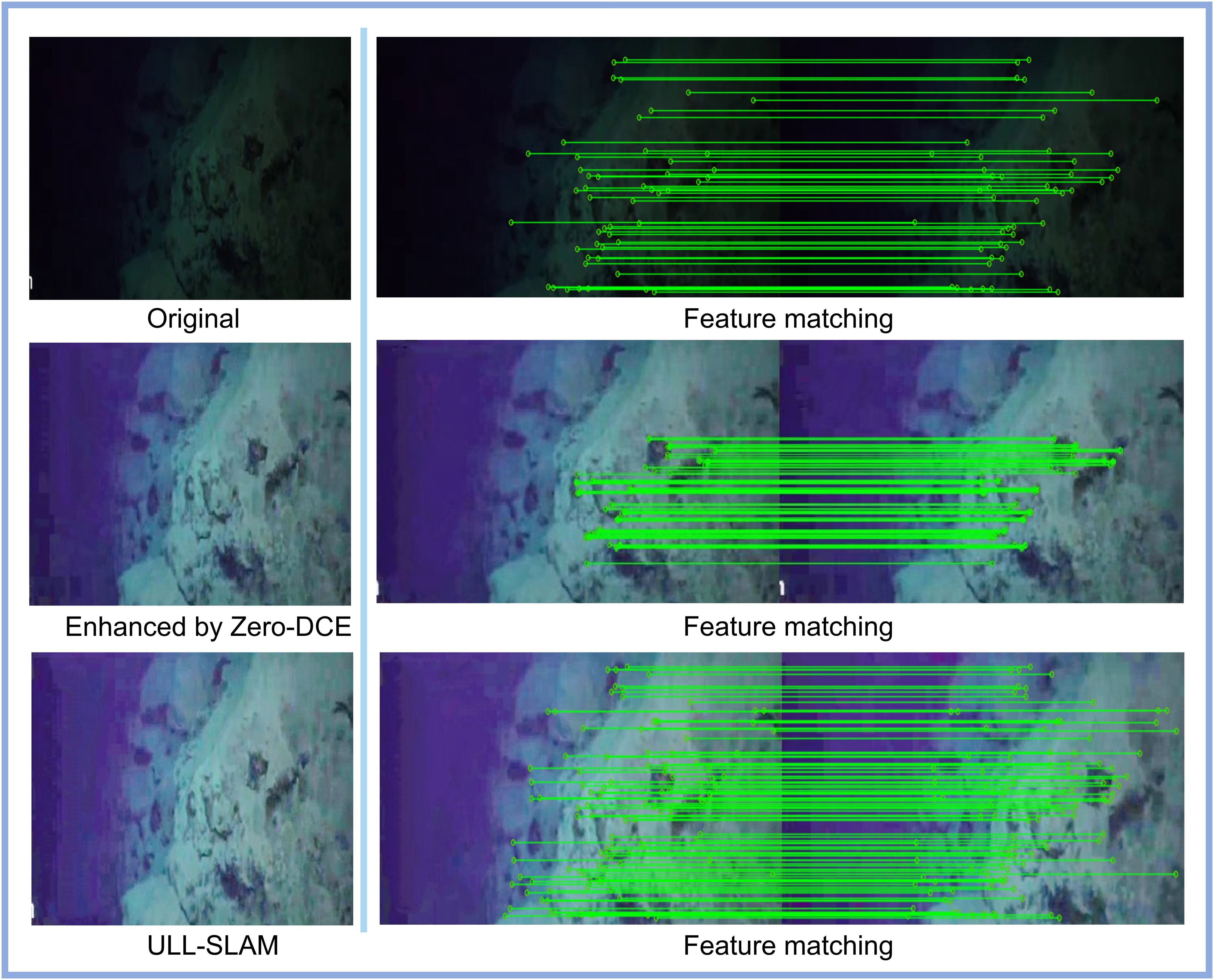
Figure 1 An image-level low-light enhancement preprocessing module (e.g., Zero-DCE Li et al. (2021)) can improve human visual perception. However, it is unlikely to improve feature point matching performance between two adjacent frames in an underwater video. The proposed ULL-SLAM, which includes a video-level low-light enhancement module, can effectively extract the feature points between two adjacent frames.
To address these issues, we propose a front-end network framework for underwater monocular SLAM based on low-light feature point extraction with siamese networks in Figure 2, named ULL-SLAM. Our ULL-SLAM can improve the performance of monocular SLAM in underwater low-light environments. This unsupervised end-to-end network architecture can effectively improve feature-matching performance, thereby obtaining better and more robust SLAM results. Our network can accomplish both low-light image enhancement and feature point extraction, and both are optimized together to enhance the low-light image enhancement network toward favorable feature point extraction and matching. Continuous image frames are input during training, and the network constrains the image enhancement followed by continuous frames to improve the performance of feature point extraction and matching between consecutive frames. Meanwhile, the image enhancement network and the feature point extraction network share the same backbone to improve the inference speed of the model and make the model capable of deployment on embedded devices. Furthermore, we have independently packaged the low-light feature point extraction network of ULL-SLAM, which can help audiences to transplant into any SLAM architecture based on feature point extraction and obtain performance gains. Finally, we evaluate our method on multiple underwater datasets. The proposed method outperforms existing methods in position estimation and system stability. In summary, our main contributions are as follows:
● We propose a mean frame loss and a temporal-spatial consistency loss to improve the ability of feature point extraction among several adjacent frames and keep the enhanced features from the adjacent frames consistent.
● We propose an adaptive low-light enhancement network with an uneven brightness loss, which can adjust the brightness of an image with an arbitrary low-light level.
● We adopt the method of the siamese network to train the network’s ability to extract feature points through homography transformation. The siamese network enables interest point scores and positions to be learned automatically.
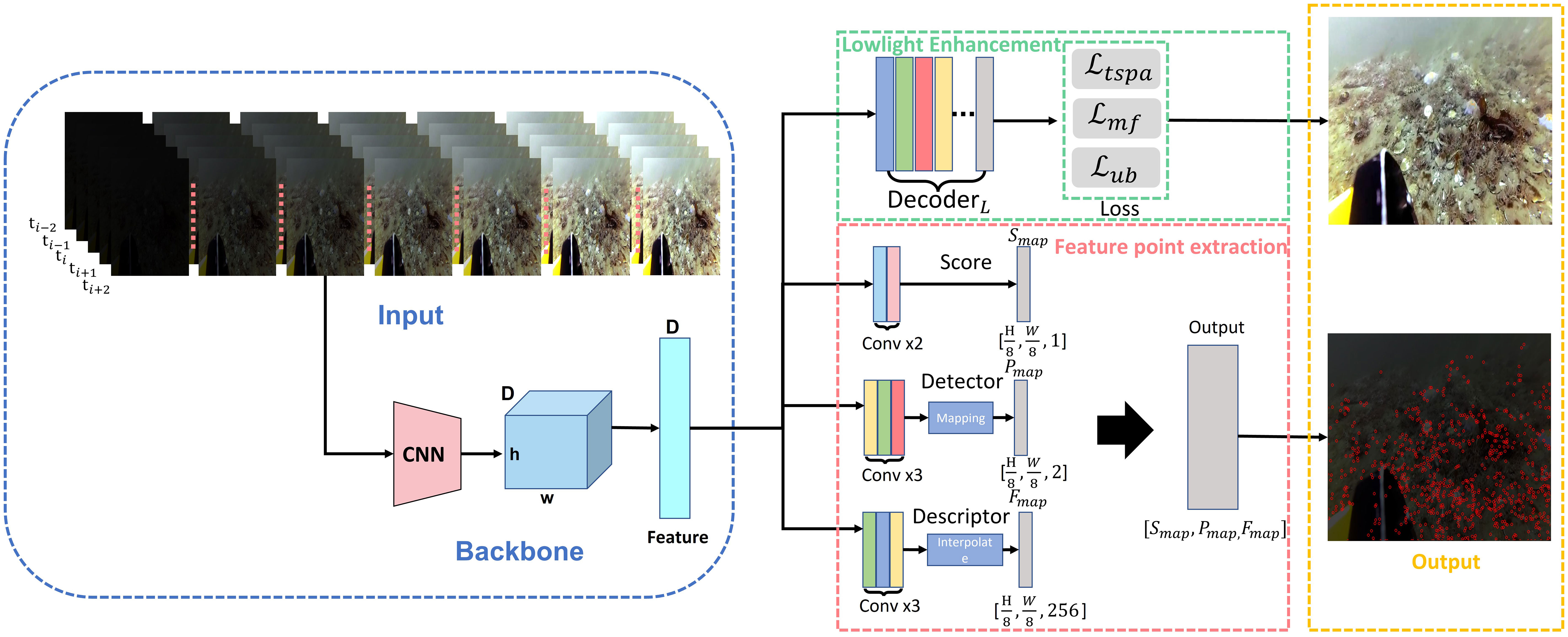
Figure 2 The overview framework of the proposed method. The green box is the low-light image enhancement branch, and the red box is the feature extraction branch. The two parts share the same backbone (in the blue box), and the orange box is the output result of the model.
2 Related work
2.1 Low light image enhancement
There are four types of popular low-light image enhancement: 1) supervised learning, 2) reinforcement learning, 3) unsupervised learning, and 4) zero-shot learning. MBLLEN Lv et al. (2018) extracted effective feature representation through a feature extraction module, an enhancement module, and a fusion module, which improves the performance of low-light image enhancement. Ren et al. Ren et al. (2019) designed a more complex end-to-end network, including an encoder-decoder network for image content enhancement and a recursive neural network for image edge enhancement. To reduce the computational burden, Li et al. Li et al. (2018) proposed LightenNet, a lightweight model for low-light image enhancement. LightenNet takes the low-light image as input to estimate its illuminance pattern. It can enhance the image by dividing the input image by the illuminance graph. In the absence of paired training data, Yu et al. Yu et al. (2018) used adversarial reinforcement learning to study the exposure of photos, which they named DeepExposure. First, the input image is segmented into sub-images based on exposure. For each sub-image, local exposures are sequentially learned through a reinforcement learning-based policy network, and the reward evaluation function is approximated by adversarial learning. EnligthenGAN Jiang et al. (2021) is based on an unsupervised learning method and addresses the problem that training a deep model on paired data may lead to overfitting and thus limit the model’s generalization ability. Supervised learning, reinforcement learning, and unsupervised learning methods either have limited generalization ability or suffer from unstable training. Zhang et al. Zhang et al. (2019) proposed a zero-shot learning method called ExCNet, which is used for backlit image in painting. It first uses a network to estimate the S-curve that best fits the input image. Once the S-curve is estimated, guided filters separate the input image into a base layer and a detail layer. The estimated S-curve then adjusts the base layer. However, most of these works are image-level models. Applying an image-level model for video preprocessing may cause features to be inconsistent between two adjacent frames. In many low-light underwater cases, the unique illumination from the underwater vehicle could be more likely to cause uneven brightness distribution than in-air cases. Unlike these works, our model includes two loss functions to ensure the enhanced underwater images can practically improve the feature points matching efficiency as well as the VLSAM performance.
2.2 Underwater SLAM
Nowadays, the popular visual SLAM system is normally based on the feature description method Rublee et al. (2011). VINS Qin et al. (2018); Qin and Shen (2018) proposed a general monocular fusion framework containing IMU information. Unlike the non-underwater environment, conventional navigation and positioning communication methods cannot be used typically underwater (such as GPS). Hence, the visual information of the underwater robot itself provides an essential guarantee for robot navigation. In the absence of GPS to generate ground truth for camera poses, a recent work employs Colmap’s Schönberger and Frahm (2016); Schönberger et al. (2016) SFM (structure-from-motion, SFM) based method to generate relatively accurate camera trajectories. To evaluate underwater SLAM performance, UW-VO Ferrera et al. (2019) uses the reconstructed trajectories as ground truth trajectory values. Due to the good properties of sound propagation in water, some sonar-based methods Rahman et al., 2018; Rahman et al., 2019a; Rahman et al., 2019b, SVIN Rahman et al. (2018) and SVin2 Rahman et al. (2019b)), incorporate additional sparse depth information from sonar sensors for more accurate position estimation. No matter which kind of feature point-SLAM system is used, the premise of its work is to be able to extract feature points. However, in deep-sea exploration, the feature points cannot be easily extracted due to the low brightness of underwater imaging and insufficient illumination. Besides, sonar sensor-based solutions Rahman et al., 2018; Rahman et al., 2019b) remain expensive, and we aim to propose a general underwater SLAM framework based on purely visual information in deep-sea low-light environments.
3 Methodology
3.1 Overall framework
Feature point extraction and matching play a key role in VSLAM process. Unfortunately, many existing low-light image enhancement works are not designed for continuous frames. An image-level preprocessing may improve human visual perception, but it may be useless for feature point extraction and matching. Moreover, the artificial illumination used for deep-sea exploration may easily cause uneven illumination. The ULL-SLAM front-end feature point extraction network uses a self-supervised siamese network training framework to learn all four tasks simultaneously; the process is shown in Figure 2. The learning tasks of the network are mainly divided into two branches: low-light image enhancement and feature point extraction. The two branches share the same backbone to reduce the model’s training time and improve the model’s inference speed, thereby ensuring that the model runs on embedded devices in real-time. The low-light image enhancement branch is responsible for enhancing the input original low-light image, and the feature point extraction branch uses the siamese network to predict the two detected feature points of the same input image.
The proposed enhancement network does not directly perform an image-to-image mapping from the low-light image to the enhanced image but rather estimates an enhancement curve from the low-light image to the enhanced image by the network, and applies the estimated enhancement curve to the low-light image to complete the low-light enhancement of the original image. Therefore, in order to make the estimated enhancement curve more accurate, images with different exposure levels of the same image are used when feeding them into the network, which is why the input part of the network frame has 7 images with different exposure levels at the same moment, as shown in Figure 3. In order to ensure the color imbalance that may occur between the front and back frames after underwater continuous frame image enhancement (e.g., the image scenes between the front and back frames do not differ much, but the enhancement effect has changed), the images at the five moments of , , , , at the input end of the network are to ensure that the texture information, color, etc. between the front and back frames of continuous frame image enhancement do not become distorted, and at the same time can complete the Feature point matching, this part is explained in detail in the ablation experiment (Figure 4) of the loss function.
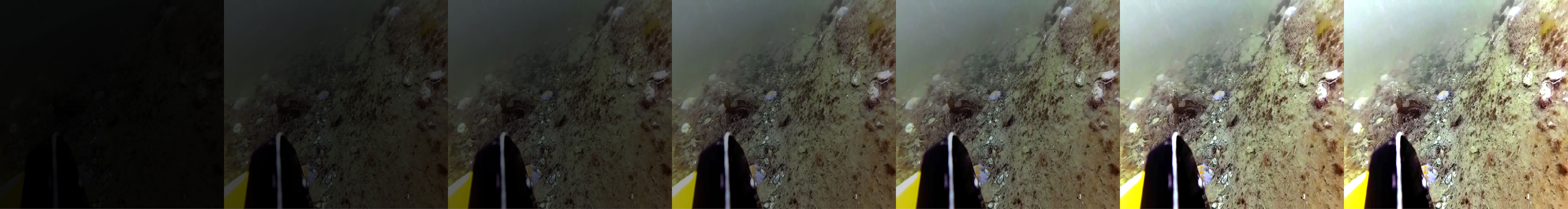
Figure 3 The images used for network training increase in brightness from left to right. Images with different exposure levels are used to improve the generalization of the augmentation network and to enhance the detection and matching ability of the feature point detection network.
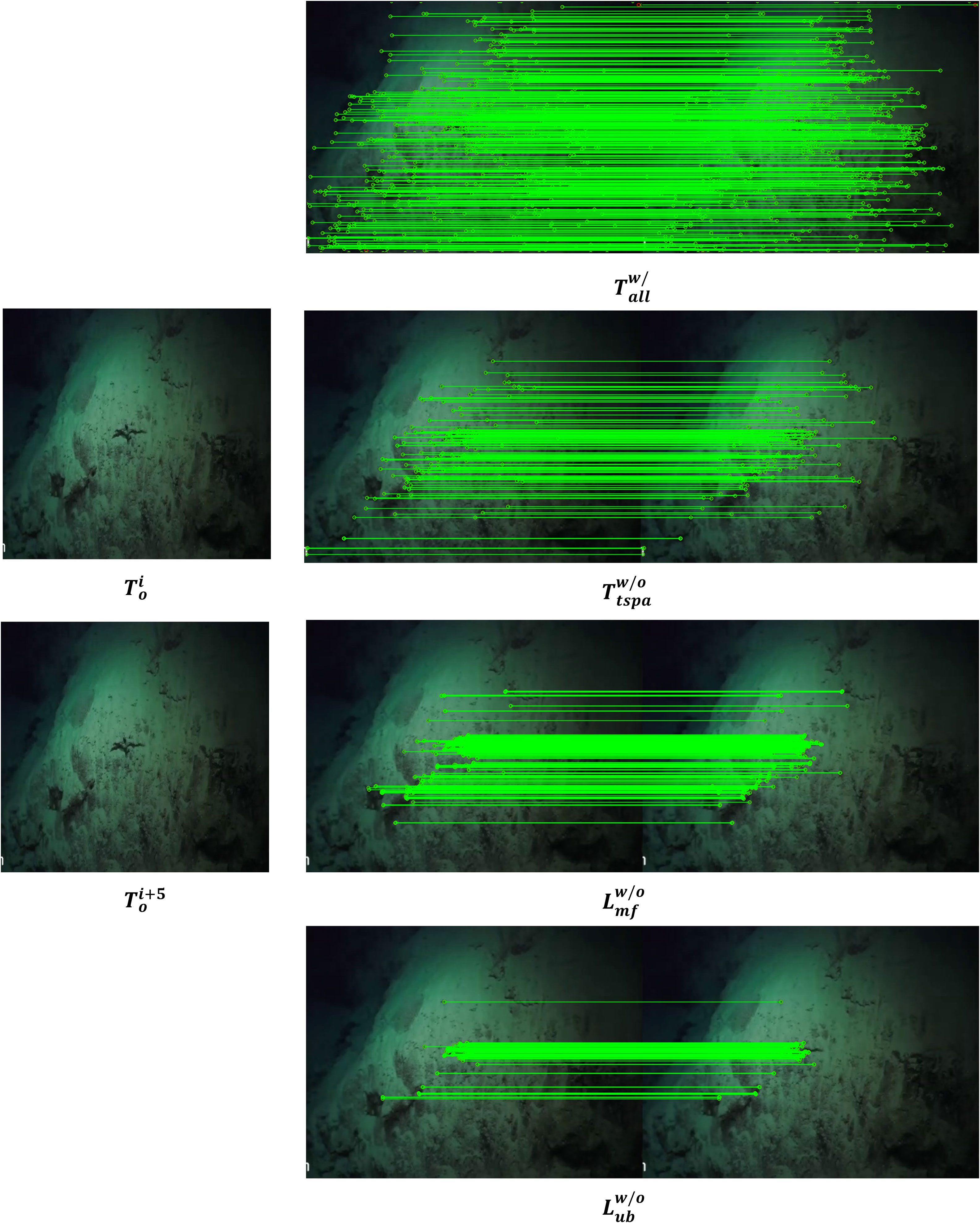
Figure 4 The ablation study of various loss functions. represents the feature point matching result when using all loss functions; represents the feature point matching result without using ; represents the feature point matching result without using ; represents the feature point matching result without using ; represents the original low-light image; represents the image of the current moment; () represents the image after the current moment.
The first step is to perform a spatial transformation (rotation, scaling, tilt, etc.) on the input image through random homography T. Through the siamese network A, output the feature points fraction a, the position a, and the descriptor sub-information a. In the second step, the input image passes through the siamese network B, and then the output result is transformed by the same random homography T to obtain the feature point score B, position B, and descriptor information B. The feature points output by the siamese network A and the siamese network B are spatially aligned, and finally, the distance between the two points is minimized in the loss function to train the network. The feature points are differentiable through the T transformation and the loss function so that each siamese network can be trained and tested end-to-end.
3.2 Backbone
The backbone network takes an input image and generates intermediate feature map representations for each subtask. The first seven convolutional layers of the backbone network are symmetrically connected. Each layer consists of 32 convolution kernels of size 3×3 with a stride of 1 followed by a ReLU activation function. The Tanh activation function follows the last convolution layer. Three max-pooling layers separate the last four pairs of convolutional layers with a stride and kernel size of 2. After each pooling layer, the number of channels in subsequent convolutional layers doubles. The number of channels for 8 convolutional layers is 32-32-64-64-128-128-256-256. Each pooling layer samples twice the height and width of the feature map, while the entire trunk samples are eight times the height and width of the feature map. An entry in the final output corresponds to 8 × 8 regions in the input image. So for an input image of 480 × 640, the network will return (480/8) · (640/8) = 4800 entries Christiansen et al. (2019). Each entry is processed on each subtask in a fully convolutional way to output descriptors, scores, and locations, effectively creating 4800 points of interest Christiansen et al. (2019).
3.3 Low-light image enhancement branch
Underwater robots usually must deal with images with dark light and uneven illumination distribution of continuous video frames in the marine environment, Zero-DCE Li et al. (2021) proposes the idea of brightening the curve as shown in Eq. 1. This function is well designed to solve the problems of the constant brightness value range, monotonically increasing brightening curve, simple curve formula and network differentiability. However, this idea does not consider that the enhanced features between two adjacent frames should be as consistent as possible. Therefore, we draw on this idea to propose a new solution based on the siamese network to deal with the low-light enhancement problem of underwater constant frame images. Specifically as follows:
where x is the pixel coordinate; is the augmented image of the input image I(x); is a trainable curve parameter that adjusts the size of the LE curve. Each pixel is normalized to [0,1], and all operations are performed pixel-wise.
3.3.1 Temporal-spatial consistency loss
Inspired by the spatial consistency loss proposed in Zero-DCE [15], we further consider the temporal relationship between two adjacent frames and propose the temporal-spatial consistency loss to extend the spatial consistency restriction from the image-level to the video level. Comparing with the defined in Zero-DCE, the proposed takes into account the spatial consistency between a source image and the homography transformation of its adjacent frame.
Let denote the siamese networks; is the raw image. Then we can use the spatial homography transformation matrix to represent the adjacent frame of the raw image as . Let us define and as the enhanced outputs from the siamese network , respectively. Then we can define the temporal-spatial consistency loss as follows:
where is the number of pixels and is the traversal of pixels, and is the 3×3 neighborhood of the pixel.
3.3.2 Mean frame loss
Our network adopts continuous video frame input for training. We propose a locally constrained loss function that stabilizes transitions between consecutive frames of enhanced images. The scene and pixel differences between consecutive frame images are minimal, and we adopt the idea of local optimization to control the drift between consecutive frame-enhanced images. The specific operations are as follows:
Here is the average pixel value of the output image of the siamese network at the current moment; M is the total number of images; n is the number of local images selected to participate in the optimization; this value is 4 in actual training.
3.3.3 Uneven brightness loss
In a deep marine environment, artificial illumination is a common light source. However, an artificial light source’s power is always insufficient to illuminate the entire area, resulting in uneven illumination. To prevent some places from being too dark and to restrain overexposure, we make the brightness of each pixel closer to a specific intermediate value. We then propose a local uniform brightness loss function, which uses the following error function to express the constraint.
where represents the average value of the local pixel area. During training, the image is divided according to the strategy that the local area is 25 pixels, and N represents the number of local pixel areas. describes the median value of the pixel area of the entire image. To prevent the overall brightness of the enhanced image from being low or over exposed, we limit its weight. When the median pixel value is lower than or higher than the set threshold, we use weight parameters and and its compensation to ensure that the generated image will not be overexposed or darkened and to maintain the generated image. The specific values in training are 1.75 and 0.7, respectively.
Meanwhile, to make the enhanced image maintain stable color and smooth illumination, we follow the color constant error loss and smooth illumination loss in Zero-DCE Li et al. (2021), as follows:
3.3.4 Color constancy loss
Zero-DCE Li et al. (2021), proposed color constancy loss corrects for potential color bias in the enhanced image and establishes the relationship between the three adjustment channels. The loss function is defined as follows:
where (p, q) traverses all pairwise combinations of the three RGB color channels, represents the average luminance of color channel p, and (p, q) represents a pair of channels.
3.3.5 Illumination smoothness loss
To maintain the monotonic relationship between adjacent pixels, we follows the illumination smoothness loss defined in Zero-DCE Li et al. (2021). This requirement can be expressed as:
N is the number of iterations, and and are the horizontal and vertical gradient operators, respectively. For images, the horizontal and vertical gradients are the difference between the values of the adjacent pixels to the left and above.
3.4 Feature point extraction branch
To calculate the loss value of the network, we need to establish the relationship between the feature points. The same image passes through the siamese networks A and B and outputs two sets of matrices , , which respectively represent the feature point scores, feature point positions, and feature point descriptors of the two images output by the network. The position of the feature points detected in image A is transformed into image B through the matrix transformation T, and obtained. and called feature point pairs, where , the distance between and is minimized. The smaller the distance between the two, the better the ability of the extraction network to extract feature points. However, not all are involved in the calculation. This is because the siamese network is uncertain about the output of the same image after matrix transformation, and there will be occasional weak feature points. Therefore, according to the experience of reprojection error in SLAM, we define that after the homography matrix transformation T DeTone et al. (2018); Christiansen et al. (2019). The distance between the feature points and the position is within the neighborhood of pixels, which means that the detected feature points are the same point in the input image. We sent the positions of such feature points to the loss function for calculation. The operation can effectively improve the stability and repeatability of network detection feature points. The Loss function is handled in the same way as UnSuperpoint Christiansen et al. (2019). We use to describe it here.
Total loss.
where weight is used to balance scales with different losses, which is a direct reference to the weight setting in Zero-DCE. The loss function sums up the loss function of the image enhancement branch and the loss function of the feature point extraction branch. By minimizing the loss function , the effect of the enhanced image can be achieved to generate in the direction favorable to feature point extraction, so that the network has the ability of feature point extraction in the underwater low-light environment.
4 Experiments
In this section, we compare the advantages of ULL-SLAM with the widespread feature point extraction based SLAM operating in a marine low-light environment. We choose ORB-SLAM2 Mur-Artal and Tardós (2017), which has stable performance in the underwater test in our laboratory, as our baseline. ORB SLAM2 is also a visual SLAM framework that can be used for monocular, stereo, and RGB-D cameras based on the extraction of feature points (ORB). A new system —ULL-SLAM is constructed by replacing its physical sign point extraction module with our underwater low-light feature point extraction network. We also compared it to the original ORB-SLAM2 Mur-Artal and Tardós (2017), ORB-SLAM3 Campos et al. (2021), and Dual-SLAM Huang et al. (2020).
● Dual-SLAM Huang et al. (2020) extends ORB-SLAM2, saves the current mapping, and activates two new SLAM threads. One handles the incoming frame to create a new map, and the other targets link the new and old maps.
● ORB-SLAM3 Campos et al. (2021) Visual, visual-inertial, and multi-map SLAM using monocular, stereo, and RGB-D cameras, achieving state-of-the-art performance.
Since we adopt a deep learning-based method to extract feature points, we test the model’s running speed (frame-per-second, FPS) on Jetson AGX Xavier, which is also widely equipped on ROV and AUV. Our ULL-SLAM can reach a speed of 40.6 FPS.
4.1 Implementation details and evaluation metrics
4.1.1 Dataset
4.1.1.1 Training dataset
The dataset Liu et al. (2021) contains contains monocular video sequences collected by the ROV on a real aquaculture farm nearby Zhangzi Island, China. The ROV can travel in water depths of about 5 meters. The ROV captured a total of 190 seconds of video sequences at a 24Hz acquisition frequency. We obtain a total of 4,538 frames from the video. The collected video sequence scene changes significantly, the light is sufficient, but the water quality is cloudy. In order to ensure that the feature point extraction branch can extract more feature points, we add the image after image sharpening in the laboratory’s previous work. The fusion of these two kinds of data not only ensures that the feature point extraction network can extract more feature points but also ensures the generalization ability and robustness of the model. The low-light image enhancement model based on zero-order learning cannot be trained typically with simple underwater images. However, acquiring underwater low-light data sets is difficult and expensive. Therefore, we adopt the idea of style transfer to transform the brightness of datasets and finally form images with different colors and brightness for training. Considering that there are no meaningful objects in the first 2000 consecutive images in the original sequence, we delete them and select only the last 2538 images, respectively, for brightness conversion. Among them, we used 1250 images for testing. In the training process, we select the open-source offline SFM Schönberger and Frahm (2016); Schönberger et al. (2016) library to generate a camera attitude track from 1250 continuous frame images to evaluate underwater SLAM performance.
4.1.1.2 Test datasets
The training data set is an artificially generated low-light image. To test the performance of ULL-SLAM in a natural underwater environment, we select five video clips of natural underwater low-light scenes from the videos provided by Schmidt Ocean Alalykina and Polyakova (2022). These video clips are captured with an underwater vehicle to a depth of 400-500 meters in the Pacific Ocean. Each video clip is 2150, 3500, 4600, 5200, and 6000 frames, respectively. The rotation and ambiguity of the image in each piece of data are different. We generate the camera pose using SFM Schönberger and Frahm (2016); Schönberger et al. (2016). We also use SFM to provide ground truth to test the performance of the ULL-SLAM system in a natural underwater low-light environment.
4.1.2 Evaluation metric for SLAM
To measure SLAM performance, we choose 1) absolute trajectory error (ATE), 2) root mean square error (RMSE), and 3) initialization performance for evaluation. ATE directly computes the difference between the ground-truth trajectory of the camera pose and the SLAM-estimated trajectory. RMSE can describe the rotational and translational errors of two trajectories. The smaller the RMSE, the better the system trajectory fit. The initialization performance indicates the number of frames to perform underwater SLAM initialization. The lower the initialization frame, the better the SLAM performs and the more stable and continuous the output. We repeated ten underwater SLAM experiments to get the best results for all methods.
where represents the system’s predicted trajectory, and represents the Groundtruth of the trajectory.
4.2 Low light enhanced visualization result
We verify the effect of the proposed loss function in this section and visualize the effect of each function separately by conducting ablation experiments during training. It is worth noting that the loss function we designed for continuous frames (Eq. 3) and overexposure (Eq. 4) mainly enables the network to have a good feature point extraction effect in the underwater low-light environment. The two networks are optimized end-to-end together rather than proposing a low-light image enhancement model. Therefore, we do not compare the performance of other low-light enhancement models on terrene in the same underwater scene. Figures 5, 6 show the comparison of the training dataset image and the real underwater test dataset image before and after the low-light enhancement network, respectively. Figure 7 verifies the ablation experiment of our proposed loss function on the low-light image enhancement effect. It should be noted that the ultimate purpose of our network is to focus on the effect of the network in feature point extraction, so Figure 4 shows the effect of our proposed loss function on feature point extraction.
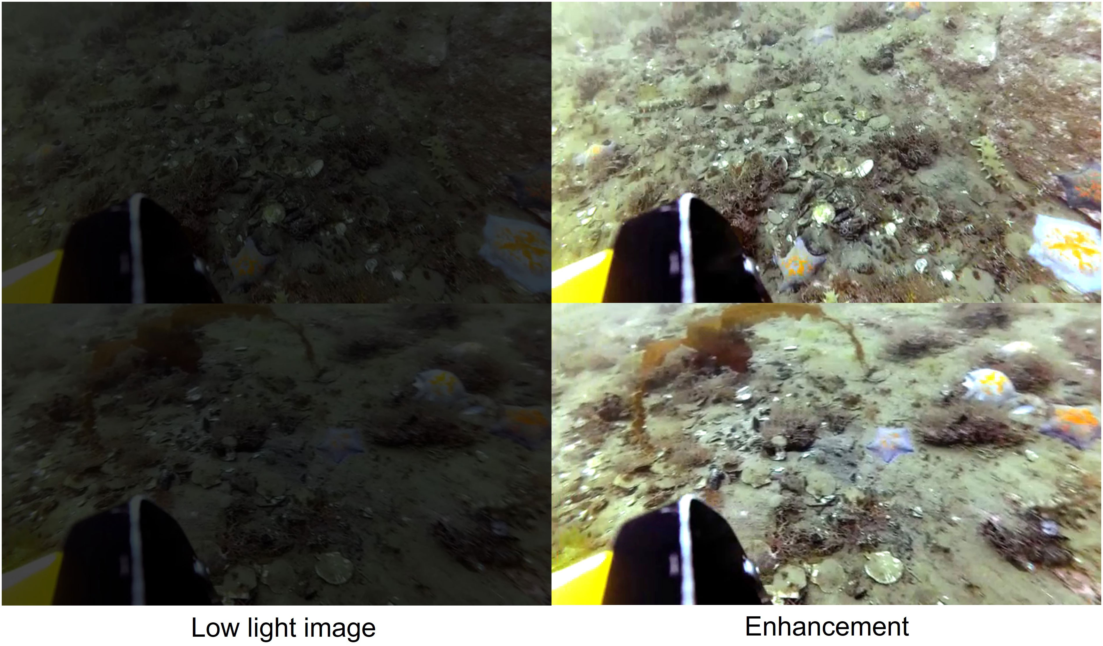
Figure 5 Comparison of low-light images before and after enhancement on URPC-dark dataset.
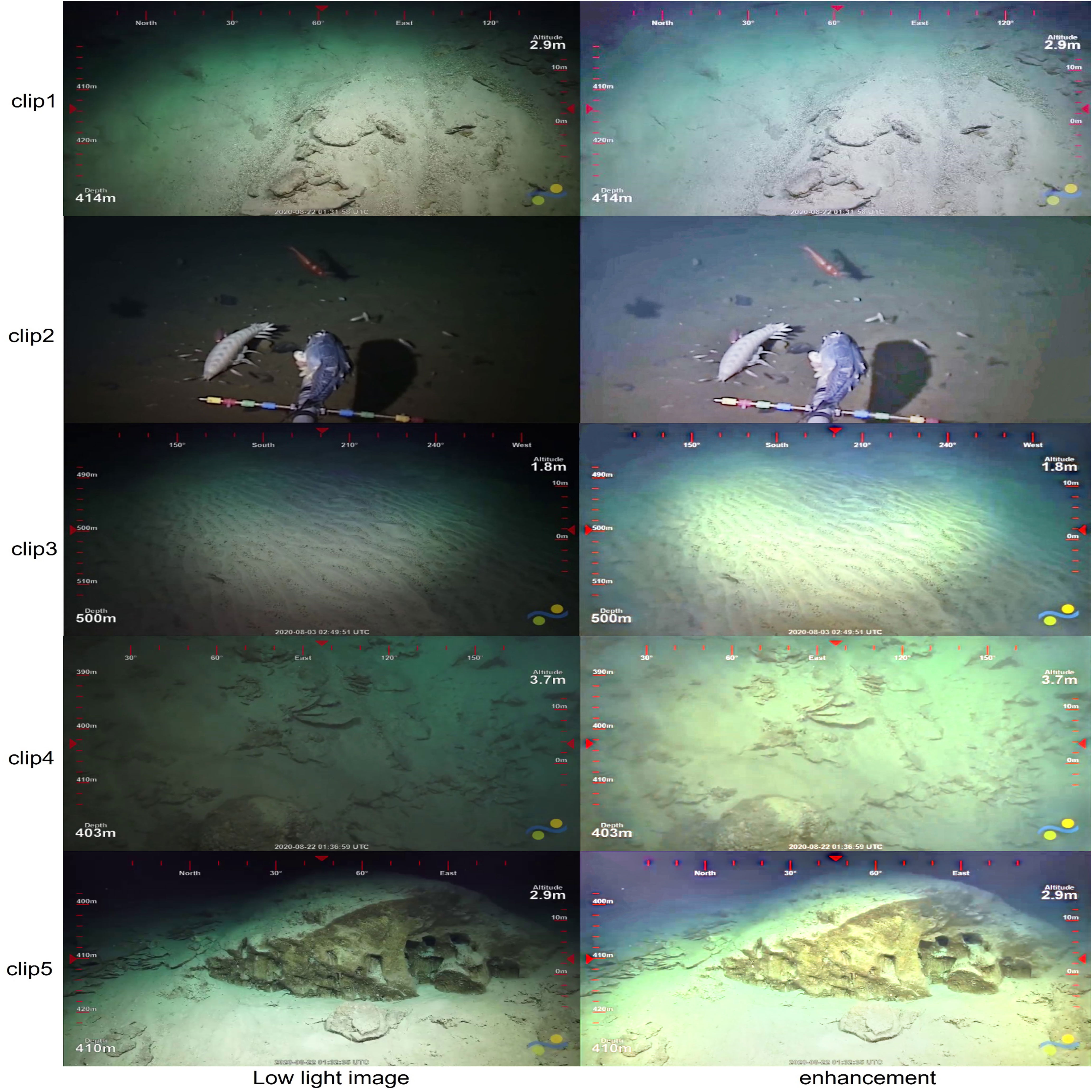
Figure 6 Comparison of low-light images before and after enhancement on real underwater dataset provided by Schmidt Ocean Alalykina and Polyakova (2022).
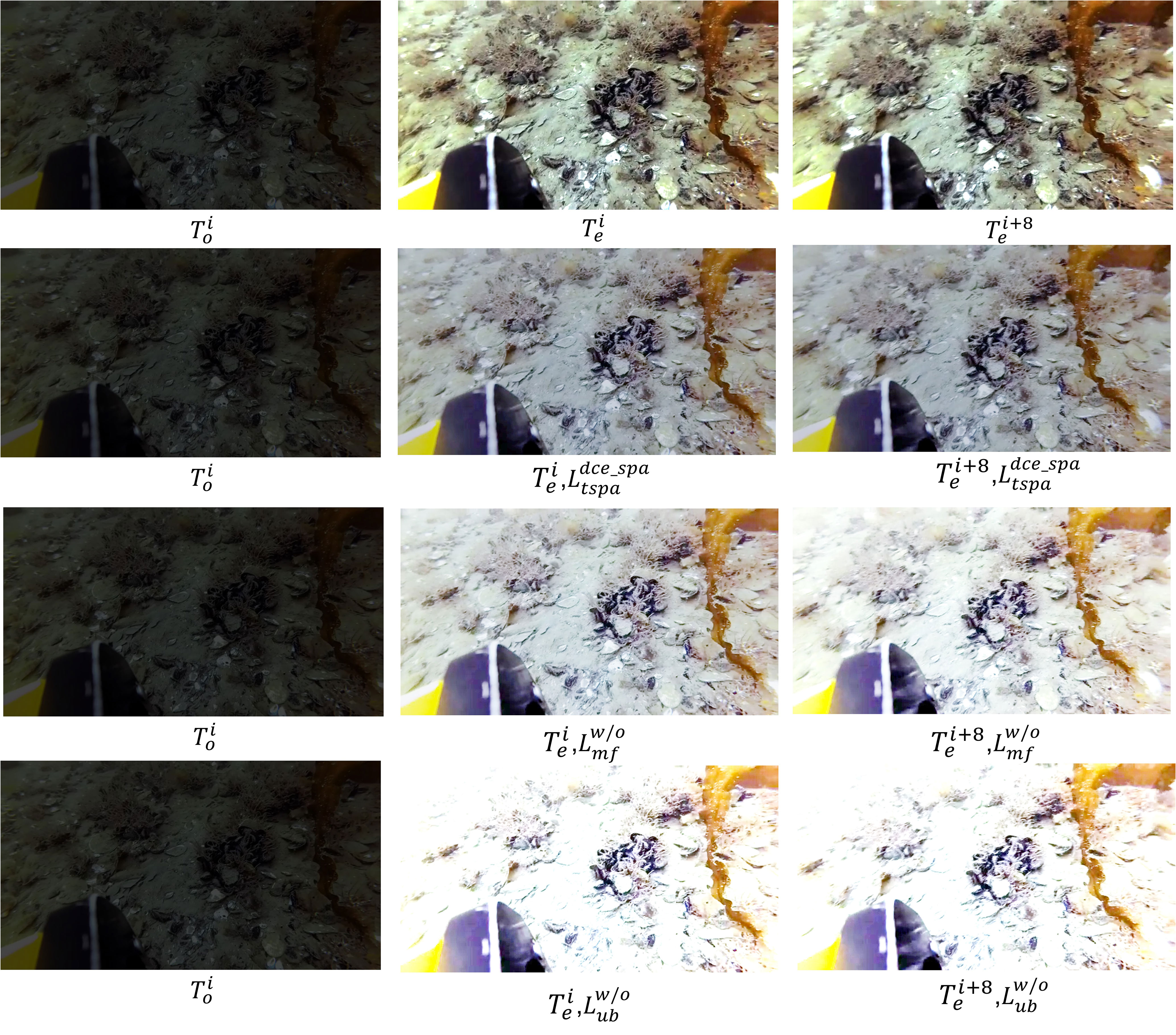
Figure 7 The ablation study of various loss functions. The first row of images represents the normal network output, represents the original low-light image, represents the image of the current moment. We select the Frame and eighth (i+8) frames after the current moment to verify the effects of different functions, represents the other functions unchanged, and the network output image after removing this function. When the loss function is removed, we can find overexposure occurs in the image after enhancement. When the loss function is removed, it can be seen that the image scene does not change significantly at the interval of 8 frames, but the enhancement effect has changed significantly.
4.3 Feature point matching performance
To further reveal the superiority of the feature point extraction effect in ULL-SLAM compared with other methods, we show the matching pairs with ORB Rublee et al. (2011), SIFT Lowe (2004), and SURF Bay et al. (2008) under two consecutive frames in Figures 8, 9. We obtain ground-truth values from motion using a structure-of-motion-based COLMAP Schönberger and Frahm (2016); Schönberger et al. (2016) method. We conduct experiments using 2150 consecutive frames of underwater images with an image size of 640x480 and pre-calibrated in-camera references. Only matching pairs in the 3×3 pixel region are considered correct matched pairs.
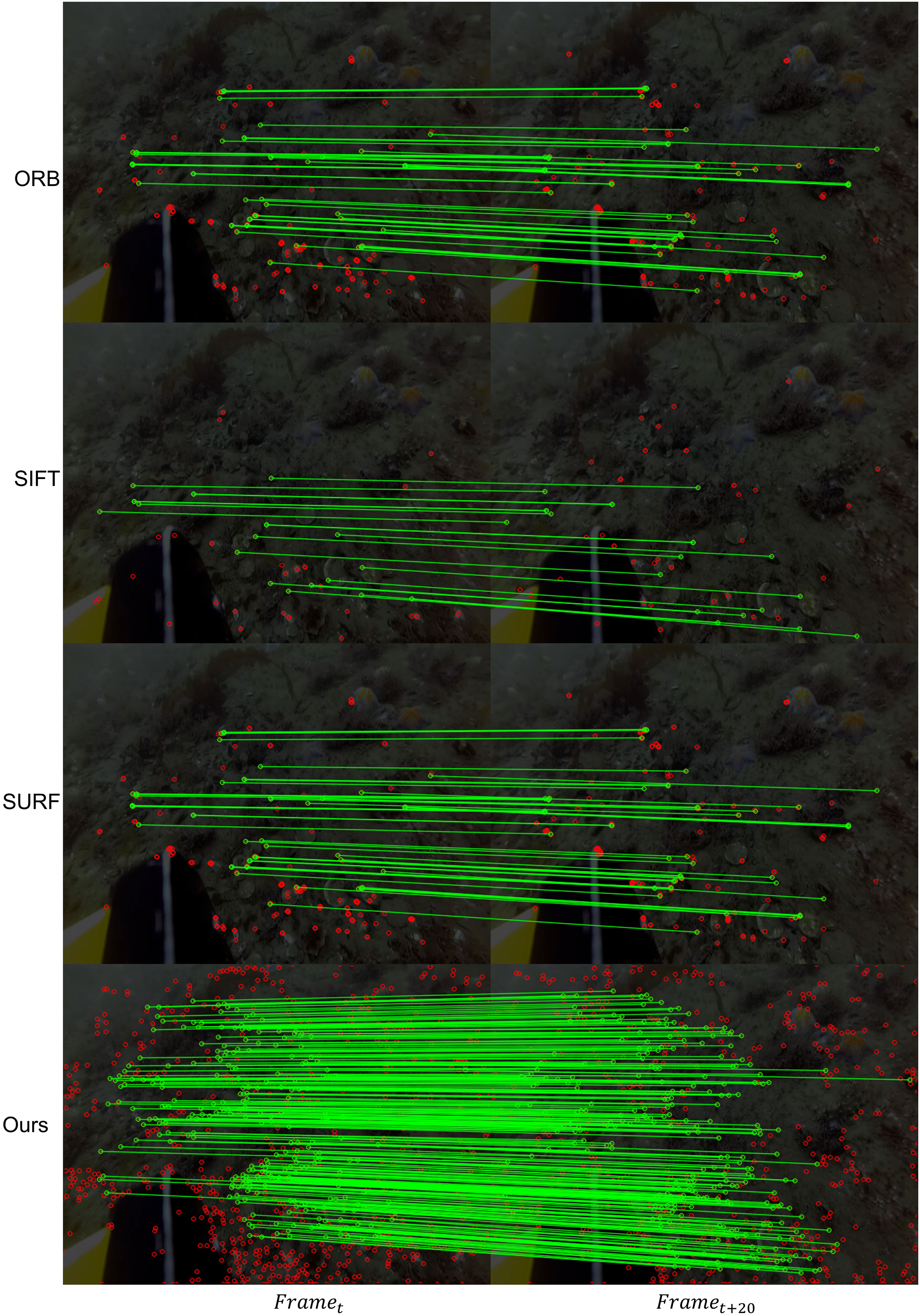
Figure 8 Comparison of extraction methods of different feature points. The image on the left is the current frame image, and the image on the right is the frame image behind the current frame image.
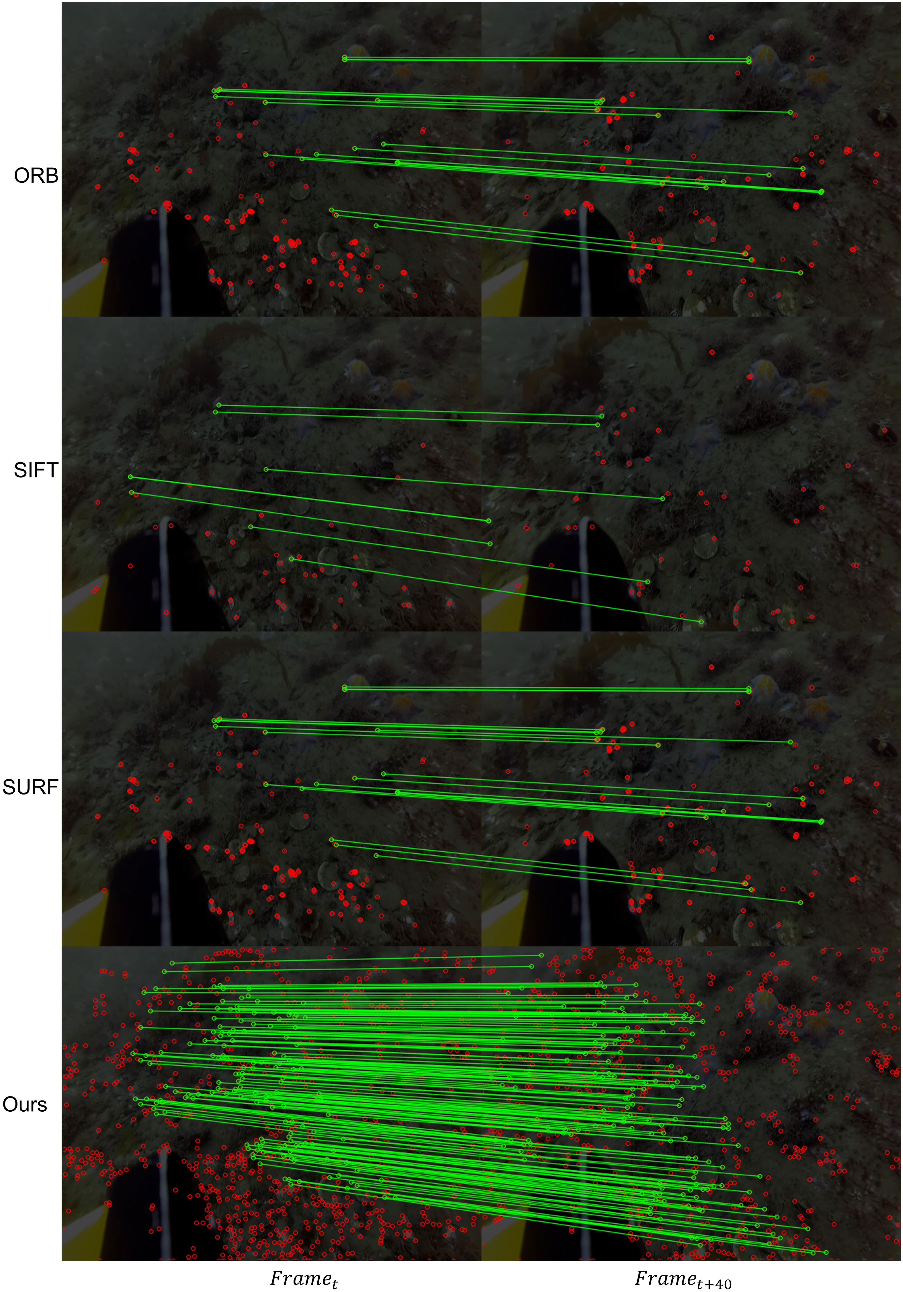
Figure 9 Comparison of extraction methods of different feature points. The image on the left is the current frame image, and the image on the right is the frame image behind the current frame image.
To verify that the feature points detected by our system are valid interior points, we conduct the feature point matching test through the reprojection error of every 20 frames of images. Specifically, the feature points extracted from the current frame are reprojected onto the previous 20th frame image to compare the errors between the feature points. Then we select a 3×3 pixel region. When the error between the feature points is less than 3, the feature point is marked as number 0 and the inner point; then, the others are marked as the mismatched outer points and number 1. Finally, the feature-matching error rate of our proposed method is 0.9%, the error rate of ORB method is 6.7, the error rate of SIFT method is 5.1, and the error rate of SURF method is 3.5. The formula is as follows:
where represents the coordinates of the feature points of the current frame, represents camera parameters, represents the transformation matrix, and represents the coordinates of the image feature point at the 20th frame interval from the current frame.
where represents the number of image pairs involved in reprojection.
To verify the ability of the system to extract feature points in a natural low-light underwater environment, we conducted a feature point detection test in the test dataset. According to the constraints of state estimation, the SLAM system outputs accurate positional estimation data only when a sufficient number of interior points are matched, and when the number of interior points is too small, it will cause the system to fail to complete the positional estimation. Therefore, we construct a test image pair at intervals of 20 and 30 frames for the test set video clips and perform feature point detection and matching tests in different feature point detectors. When the number of feature points detected between the two frames of the test image pair is greater than 50, we record the correct samples and calculate the proportion of the accurate sample numbers in all test pairs of the video clip. When the system is able to detect enough feature points at 20 or 30 frames between keyframes, it proves that the feature point matching capability of the network is good enough. The performance of the system is demonstrated by verifying the matching ability of the proposed network feature points. In this way, we use this method to compare the ability of network feature point detection. The test results are shown in Tables 1, 2.
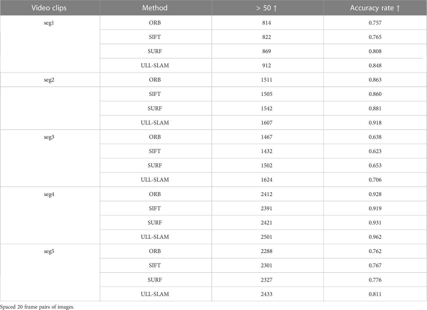
Table 1 Feature point detection effect of different feature point detectors in a real underwater environment.
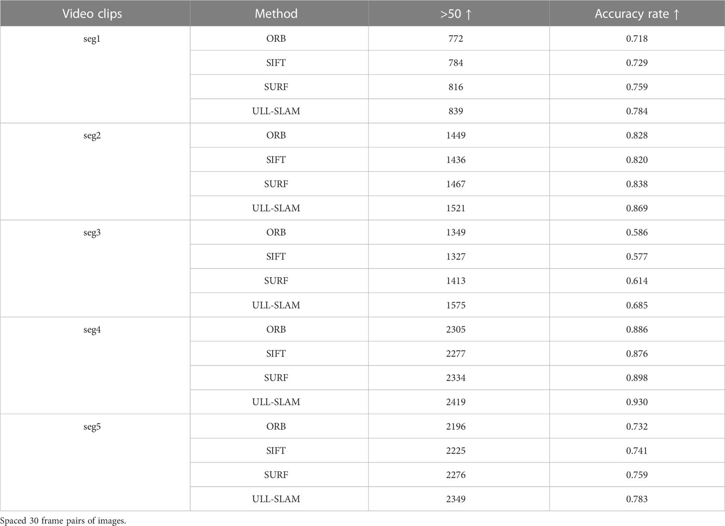
Table 2 Feature point detection effect of different feature point detectors on the dataset provided by Schmidt Ocean.
Similarly, we propose a SLAM system and pay more attention to the effectiveness of the extracted feature points on the SLAM system. There is no direct proportion between the number of matching feature points and the performance of SLAM. Therefore, in the comparison experiment, we only select the feature point extraction methods commonly used in the current SLAM system, such as (ORB). Other feature point extraction networks based on deep learning only focus on feature point extraction and have yet to be transplanted into the SLAM system, so we did not compare them.
4.4 Underwater SLAM results
We aim to validate the proposed network model in low-light feature points Extraction SLAM and the system’s effectiveness. We adopt the ORB-SLAM2 of the stability of the effect in the early stage of the laboratory experiment as the basic SLAM framework. Our model replaces the ORB feature point extraction network in the original system, keeping the back-end optimization architecture with the original method unchanged, forming a new SLAM system – ULL-SLAM. Our model replaces the ORB feature point extraction network in the original system, keeping the back-end optimization architecture with the original method unchanged, forming a new SLAM system – ULL-SLAM. It conducts comparative experiments with the original ORB-SLAM and the currently popular Dual-SLAM and ORB-SLAM3 on the URPC-dark dataset. The quantification results are shown in Table 3. From the results, it can be found that the quantization error of ULL-SLAM is significantly smaller than the other three, and the minor quantization error can make the estimated camera pose trajectory more stable, thereby considerably improving the initial performance. An excellent low-light feature point extraction network can make feature matching more reliable so that ULL-SLAM can obtain a more stable and accurate output.
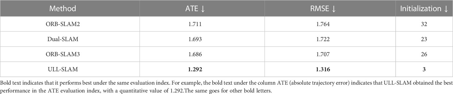
Table 3 Quantization errors of different SLAM systems on URPC-dark test dataset.
In the five real underwater low-light scenes, we use Zero-DCE as the pre-processing of underwater low-light image enhancement tool. Then, we feed the enhanced images into ORB-SLAM2 for testing. As shown in Table 4, ORB-SLAM2 did not improve all the data sets. The results indicate that an image-level low-light enhancement network can hardly improve the feature point matching and SLAM’s performance.
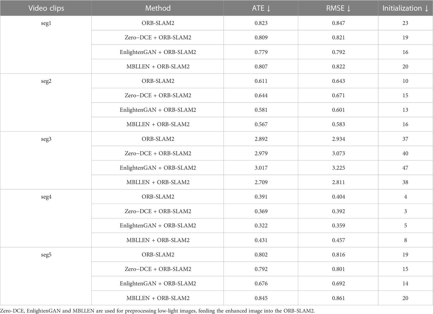
Table 4 Comparative experiments on the dataset provided by Schmidt Ocean.
We compared the performance of ULL-SLAM and the other three SLAM systems in five real underwater low-light video clips on the test set provided by Schmidt Ocean. The visualization results of the test tracks of these four SLAM systems are shown in Figure 10. We can find that the SLAM trajectory obtained with ULL-SLAM is closest to the ground truth. Meanwhile, Table 5 shows the quantization error data of the four systems in the five video clips. The two experimental results confirm that the ULL-SLAM system can achieve the expected effect in the authentic underwater low-light environment, which verifies that our proposed scheme can be well applied in the underwater low-light environment.
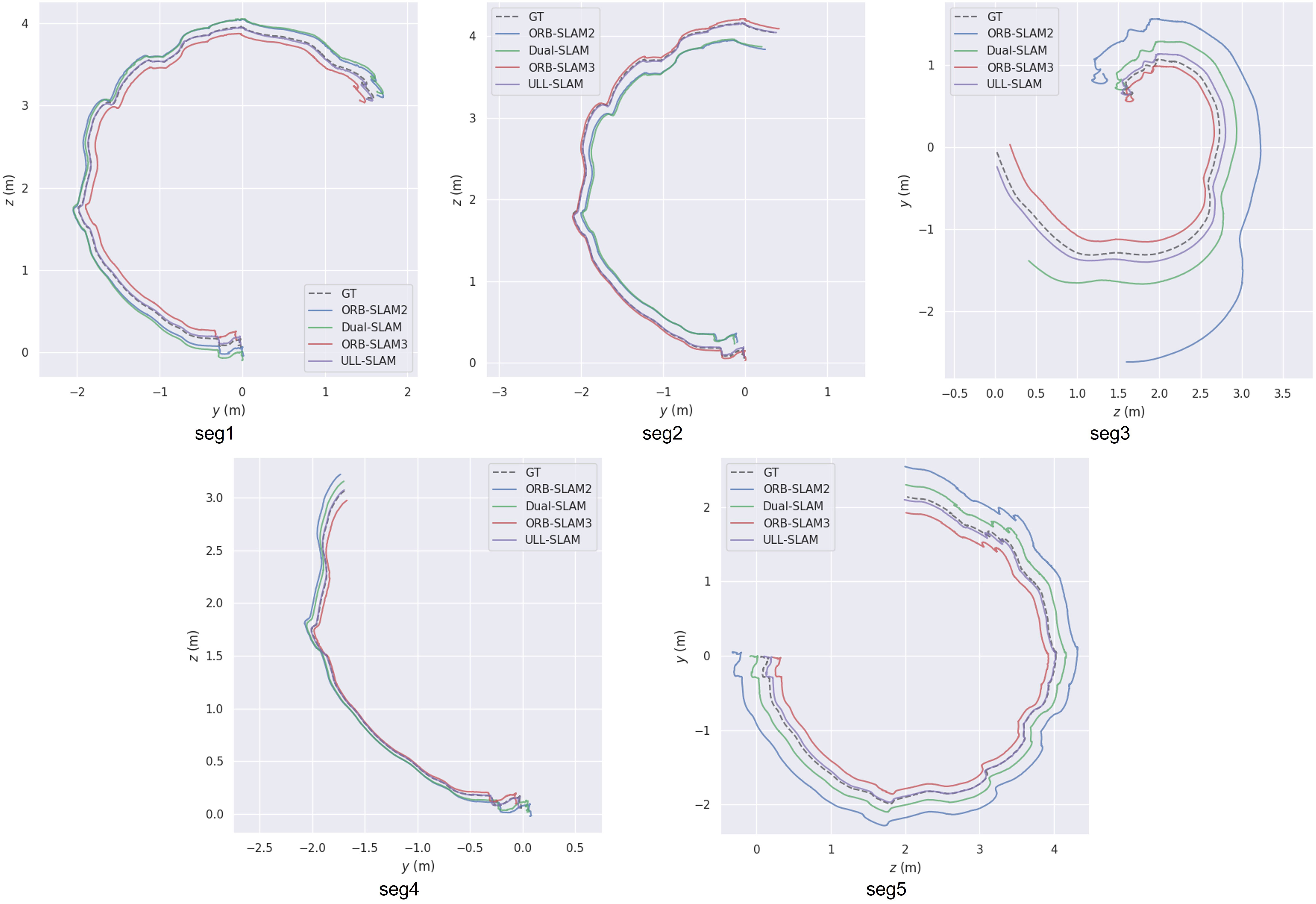
Figure 10 The performance of different SLAM systems on five real-life underwater low-light video segments.
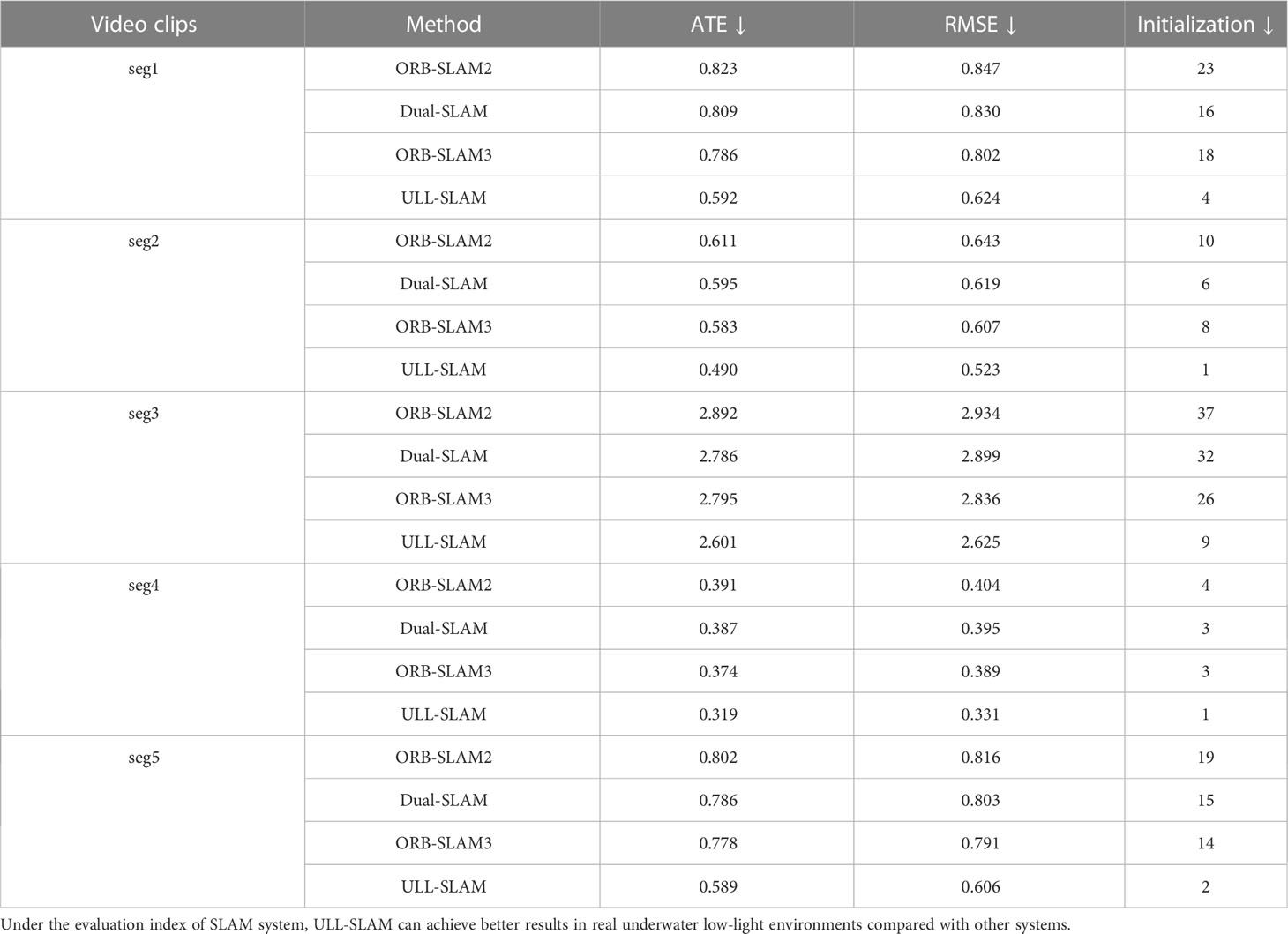
Table 5 ULL-SLAM and three other SLAM systems performed in five segments of real underwater low-light environments in the test dataset provided by Schmidt Ocean.
4.5 Limitations and future work
The low-light image enhancement branch and feature point extraction branch share the same network and are optimized end-to-end, which can complement each other for mutual benefit and improve operational efficiency simultaneously. However, we did not consider a de-scattering module to remove forward and backward scattering noise for underwater exploration. We aim to build a universal underwater visual SLAM framework that is robust to various underwater conditions. We leave it as our subsequent work.
5 Conclusion
In this paper, we propose an underwater low-light feature point extraction network based on siamese networks and integrate it into the back-end framework of the SLAM system to form a new SLAM system—ULL-SLAM. To improve the inference speed of the model to achieve real-time performance, we designed the low-light image enhancement branch and the feature point extraction branch with the same backbone. Moreover, the loss functions of the two branches are optimized together so that the low-light image enhancement branch can generate feature images beneficial to feature point detection. Thus the two are mutually beneficial. At the same time, the proposed network can be flexibly transplanted to the popular SLAM system based on feature point extraction to improve the system’s performance. Experimental results show that this method makes the output trajectory of SLAM more continuous and stable in an underwater low-light environment and carries out more accurate state estimation.
Data availability statement
The original contributions presented in the study are included in the article/Supplementary Material. Further inquiries can be directed to the corresponding author.
Author contributions
ZX is responsible for the design of the experiment and the implementation of the algorithm, ZW is responsible for drawing, and ZY and BZ are responsible for the idea and editing of the paper. All authors contributed to the article and approved the submitted version.
Funding
This work was supported by the Hainan Province Science and Technology Special Fund of China (Grant No. ZDYF2022SHFZ318), the Project of Sanya Yazhou Bay Science and Technology City (Grant No. SCKJ-JYRC-2022-102) and the National Natural Science Foundation of China (Grant No. 62171419).
Conflict of interest
The authors declare that the research was conducted in the absence of any commercial or financial relationships that could be construed as a potential conflict of interest.
Publisher’s note
All claims expressed in this article are solely those of the authors and do not necessarily represent those of their affiliated organizations, or those of the publisher, the editors and the reviewers. Any product that may be evaluated in this article, or claim that may be made by its manufacturer, is not guaranteed or endorsed by the publisher.
References
Alalykina I. L., Polyakova N. E. (2022). New species of ophryotrocha (annelida: dorvilleidae) associated with deep-sea reducing habitats in the bering sea, northwest pacific. Deep Sea Res. Part II: Top. Stud. Oceanog. (Elsevier) 206, 105217.
Bay H., Ess A., Tuytelaars T., Van Gool L. (2008). Speeded-up robust features (surf). Comput. Vision imag. understanding 110, 346–359. doi: 10.1016/j.cviu.2007.09.014
Bresson G., Alsayed Z., Yu L., Glaser S. (2017). Simultaneous localization and mapping: a survey of current trends in autonomous driving. IEEE Trans. Intelligent Vehicles 2, 194–220. doi: 10.1109/TIV.2017.2749181
Buscher E., Mathews D. L., Bryce C., Bryce K., Joseph D., Ban N. C. (2020). Applying a low cost, mini remotely operated vehicle (rov) to assess an ecological baseline of an indigenous seascape in canada. Front. Mar. Sci. 7, 669. doi: 10.3389/fmars.2020.00669
Campos C., Elvira R., Rodríguez J. J. G., Montiel J. M., Tardós J. D. (2021). Orb-slam3: an accurate open-source library for visual, visual–inertial, and multimap slam. IEEE Trans. Robot. (IEEE). doi: 10.1109/TRO.2021.3075644
Carreras M., Hernández J. D., Vidal E., Palomeras N., Ribas D., Ridao P. (2018). Sparus ii auv–-a hovering vehicle for seabed inspection. IEEE J. Oceanic Eng. 43, 344–355. doi: 10.1109/JOE.2018.2792278
Christiansen P. H., Kragh M. F., Brodskiy Y., Karstoft H. (2019). Unsuperpoint: end-to-end unsupervised interest point detector and descriptor. arXiv preprint arXiv:1907.04011.
DeTone D., Malisiewicz T., Rabinovich A. (2018)Superpoint: self-supervised interest point detection and description (Accessed Proceedings of the IEEE conference on computer vision and pattern recognition workshops).
Ferrera M., Moras J., Trouvé-Peloux P., Creuze V. (2019). Real-time monocular visual odometry for turbid and dynamic underwater environments. Sensors 19, 687. doi: 10.3390/s19030687
García S., López M. E., Barea R., Bergasa L. M., Gómez A., Molinos E. J. (2016)Indoor slam for micro aerial vehicles control using monocular camera and sensor fusion (IEEE) (Accessed 2016 international conference on autonomous robot systems and competitions (ICARSC)).
Hoegh-Guldberg O., Mumby P. J., Hooten A. J., Steneck R. S., Greenfield P., Gomez E., et al. (2007). Coral reefs under rapid climate change and ocean acidification. Science 318, 1737–1742. doi: 10.1126/science.1152509
Huang H., Lin W.-Y., Liu S., Zhang D., Yeung S.-K. (2020)Dual-slam: a framework for robust single camera navigation (IEEE) (Accessed 2020 IEEE/RSJ International Conference on Intelligent Robots and Systems (IROS)).
Huvenne V. A., Robert K., Marsh L., Iacono C. L., Le Bas T., Wynn R. B. (2018). “Rovs and auvs,” in Submarine geomorphology (Springer), 93–108.
Jiang Y., Gong X., Liu D., Cheng Y., Fang C., Shen X., et al. (2021). Enlightengan: deep light enhancement without paired supervision. IEEE Trans. Image Process. 30, 2340–2349. doi: 10.1109/TIP.2021.3051462
Li C., Guo C., Loy C. C. (2021). Learning to enhance low-light image via zero-reference deep curve estimation. arXiv preprint arXiv:2103.00860.
Li C., Guo J., Porikli F., Pang Y. (2018). Lightennet: a convolutional neural network for weakly illuminated image enhancement. Pattern recognit. Lett. 104, 15–22. doi: 10.1016/j.patrec.2018.01.010
Liu C., Li H., Wang S., Zhu M., Wang D., Fan X., et al. (2021)A dataset and benchmark of underwater object detection for robot picking (IEEE) (Accessed 2021 IEEE International Conference on Multimedia & Expo Workshops (ICMEW)).
Lore K. G., Akintayo A., Sarkar S. (2017). Llnet: a deep autoencoder approach to natural low-light image enhancement. Pattern Recognit. 61, 650–662. doi: 10.1016/j.patcog.2016.06.008
Lowe D. G. (2004). Distinctive image features from scale-invariant keypoints. Int. J. Comput. Vision 60, 91–110. doi: 10.1023/B:VISI.0000029664.99615.94
Lv F., Lu F., Wu J., Lim C. (2018). “Mbllen: low-light image/video enhancement using cnns,” in BMVC, vol. 220. , 4.
Mur-Artal R., Tardós J. D. (2017). Orb-slam2: an open-source slam system for monocular, stereo, and rgb-d cameras. IEEE Trans. Robot. 33, 1255–1262. doi: 10.1109/TRO.2017.2705103
Qin T., Li P., Shen S. (2018). Vins-mono: a robust and versatile monocular visual-inertial state estimator. IEEE Trans. Robot. 34, 1004–1020. doi: 10.1109/TRO.2018.2853729
Qin T., Shen S. (2018)Online temporal calibration for monocular visual-inertial systems (IEEE) (Accessed 2018 IEEE/RSJ International Conference on Intelligent Robots and Systems (IROS)).
Rahman S., Li A. Q., Rekleitis I. (2018)Sonar visual inertial slam of underwater structures (IEEE) (Accessed 2018 IEEE International Conference on Robotics and Automation (ICRA)).
Rahman S., Li A. Q., Rekleitis I. (2019a)Contour based reconstruction of underwater structures using sonar, visual, inertial, and depth sensor (IEEE) (Accessed 2019 IEEE/RSJ International Conference on Intelligent Robots and Systems (IROS)).
Rahman S., Li A. Q., Rekleitis I. (2019b)Svin2: an underwater slam system using sonar, visual, inertial, and depth sensor (IEEE) (Accessed 2019 IEEE/RSJ International Conference on Intelligent Robots and Systems (IROS)).
Ren W., Liu S., Ma L., Xu Q., Xu X., Cao X., et al. (2019). Low-light image enhancement via a deep hybrid network. IEEE Trans. Image Process. 28, 4364–4375. doi: 10.1109/TIP.2019.2910412
Rublee E., Rabaud V., Konolige K., Bradski G. (2011)Orb: an efficient alternative to sift or surf (Ieee) (Accessed 2011 International conference on computer vision).
Schönberger J. L., Frahm J.-M. (2016)Structure-from-motion revisited (Accessed Proceedings of the IEEE conference on computer vision and pattern recognition).
Schönberger J. L., Zheng E., Frahm J.-M., Pollefeys M. (2016)Pixelwise view selection for unstructured multi-view stereo (Springer) (Accessed European conference on computer vision).
Yu R., Liu W., Zhang Y., Qu Z., Zhao D., Zhang B. (2018). Deepexposure: learning to expose photos with asynchronously reinforced adversarial learning. Adv. Neural Inf. Process. Syst. 31.
Keywords: self-supervised learning, VSLAM, feature point matching, underwater low-light enhancement, end-to-end network
Citation: Xin Z, Wang Z, Yu Z and Zheng B (2023) ULL-SLAM: underwater low-light enhancement for the front-end of visual SLAM. Front. Mar. Sci. 10:1133881. doi: 10.3389/fmars.2023.1133881
Received: 29 December 2022; Accepted: 13 April 2023;
Published: 08 May 2023.
Edited by:
Hongsheng Bi, University of Maryland, College Park, United StatesReviewed by:
Huimin Lu, Kyushu Institute of Technology, JapanYounggun Cho, Inha University, Republic of Korea
Copyright © 2023 Xin, Wang, Yu and Zheng. This is an open-access article distributed under the terms of the Creative Commons Attribution License (CC BY). The use, distribution or reproduction in other forums is permitted, provided the original author(s) and the copyright owner(s) are credited and that the original publication in this journal is cited, in accordance with accepted academic practice. No use, distribution or reproduction is permitted which does not comply with these terms.
*Correspondence: Zhibin Yu, yuzhibin@ouc.edu.cn