Coastal wave-energy attenuation by artificial wooden fences deployed for mangrove restoration: an experimental study
 Anping Shu
 Jiapin Zhu
 Baoshan Cui
 Le Wang
 Ziru Zhang
 Chengling Pi
- 1Key Laboratory of Water and Sediment Sciences of MOE, School of Environment, Beijing Normal University, Beijing, China
- 2School of Water Resources and Hydropower Engineering, North China Electric Power University, Beijing, China
By offering natural protection along offshore wetlands, mangroves play a crucial role in providing great ecological and economic benefits to local communities. However, mangroves are currently facing an increasing threat of decline worldwide due to widespread human activities and climate change. Recently, eco-friendly wooden fences have been deployed along eroded coasts for mangrove restoration projects, and these fences have the capability to attenuate incoming waves and strengthen sediment deposition in new habitats for mangrove colonization and persistence. However, the design and performance of the fences used can differ substantially among different projects; therefore, it is necessary to study the major factors affecting the wave dissipation performance of these fences and find out a more effective structural design. Thus, we focus on two distinct types of fences with and without porous infill to study the function of infill porosity and frame density, and physical experiments of waves transmission through the fences were carried out in a wave flume, in which nine wooden fences with varied infill porosities (0.60–0.90) and frame densities (0.40 and 0.70) were predetermined to measure the wave transmission, reflection, and wave dissipation. In total, 180 experimental runs were conducted under 18 wave conditions with different wave steepness. The results showed that the fence with a lower infill porosity appears to increase wave transmission coefficient that comes at a cost of a higher reflection coefficient and less wave-energy dissipation inside the fence, and the fence with the highest porosity infills (90%) is nearly equivalent to the fence without any infills but a dense frame in terms of wave damping performance. Moreover, the wave transmission through both fences with and without infill can be remarkably affected by incoming wave steepness. The outcome of the research is not only indicating the importance of the appropriate infill porosity in attenuating incoming waves but also guiding the design of mangrove restoration project in offshore wetlands.
1 Introduction
Mangroves are unique woody plant communities that live in intertidal zones and are widely distributed in tropical estuaries and coasts under the influences of tides, stormy waves, and salinity (Van der Stocken et al., 2019). As the most biomass-rich and productive areas on the planet (Atwood et al., 2017; Simard et al., 2018), mangroves provide enormous ecological services, such as habitat provision (Robertson and Duke, 1987; Luther and Greenberg, 2009), biodiversity (Leung and Cheung, 2017; Tran and Fischer, 2017), coastal protection (Danielsen et al., 2005; Yanagisawa et al., 2010; Marois and Mitsch, 2015), and carbon sequestration (Kristensen et al., 2008; Mcleod et al., 2011). However, due to human activities and climate change, one-third of the world’s mangroves have been lost over the past 60 years (Flores-de-Santiago et al., 2017). Many beneficial initiatives have been undertaken to replant mangroves through many conservation programs around the world. Unfortunately, many restoration projects failed due to natural and societal causes (Van Loon et al., 2016), with a poor survival rate of mangrove seedlings; effective restoration program strongly require a proper habitat for mangroves to survive (Lewis, 2005). According to the theory of window of opportunity (Balke et al., 2011), the initial establishment process of mangrove seedlings on bared tidal flats is directly subject to hydraulic disturbance and sediment erosion from waves within a few days at least. Due to prolonged flooding and high waves, it is impossible for mangroves to grow in a deep-water tidal flat without damage and impact. Therefore, efforts to reduce waves and increase wetland elevation are essential during the planting (Mai Van et al., 2021). During the process of mangrove afforestation, the impact of wind and waves on the afforestation site can be mitigated by constructing various permanent or semi-permanent breakwater structures such as wooden piles, rubble mounds, and concrete breakwaters (Kamali and Hashim, 2011; Nguyen and Parnell, 2017; Le Xuan et al., 2022). The primary purpose of deploying these structures is to attenuate incident waves, and the reduced wave disturbance behind the structures will enhance sediment settlement, which facilitates shoreline expansion and mangrove colonization (Saengsupavanich, 2013), especially sheltering the growth of mangrove seedlings in the early stages of afforestation.
Recently, there are relevant researches concentrated on eco-friendly protective fences which made use of locally available materials such as bamboo poles and brushwood as sustainable and feasible measures to protect mangrove afforestation from shoreline erosion. This solution is more convenient and economical than permanent breakwaters, especially for coastal areas with unstable foundations formed by silt and swamps (Mai Van et al., 2021), and has been widely used for mangrove shoreline protection in Southeast Asia and South America (Winterwerp et al., 2013; Van Cuong et al., 2015). These fences usually have similar structures featuring one or more rows of bamboo poles driven vertically into the ground, connected to horizontal bamboo poles, or filled with brushwood or bamboo sticks between the two rows (Gijón Mancheño et al., 2021). In practical applications, more bamboo poles are required for each row to ensure the wave-damping effect without porous infill. Under the framework of a GIZ-funded (German Agency for International Cooperation) project on coastal zone management in Vietnam, Albers and Schmitt (2015) revealed that fences consisting of two rows of bamboo poles and porous infill are very effective in reducing coastal erosion and enhancing sedimentation in several eroded sea areas in Soc Trang Province, in which the outer frame serves mainly as fixation to ensure that the infill will resist the damage of currents and waves. In addition, in another GIZ project, Van Cuong and Brown (2012) used two types of fences made of melaleuca poles and branches with fish nets and bamboo mats for a mangrove planting project along the coast of Kien Giang Province to reduce wave energy and prevent sediment erosion. It was claimed that the fences reduced wave energy by up to 63%, retained sediment deposits up to 20-cm depth per year and up to 700 tons per hectare, and effectively protected all planted or naturally recruited mangrove seedlings, even in severe erosion sites.
However, numerous factors are found to influence the actual wave dissipation performance of these fences, including the structural design as well as the wave characteristics (Li et al., 2012; Kazemi et al., 2020). The wave dissipation that originated from simple but widely used bamboo poles array without porous infill has been quantitatively described by experimental and numerical studies (Mendez and Losada, 2004; Augustin et al., 2009), and the factors affecting the performance of such fences to dissipate wave energy include the density, diameter and arrangement of cylinders, and frontal contacting area (Armono et al., 2021). Many studies have focused on determining the bulk drag coefficient of the cylinder array to reveal the wave transmission mechanism (van Wesenbeeck et al., 2022). Meanwhile, for the fence with porous infill, continuous monitoring by Albers et al. (2013) showed that one of the main factors that dictate the wave dissipation effect of bamboo fence is the relative fence freeboard, but the influence of the porosity of infill material on the wave dissipation has not been fully investigated. Albers and Von Lieberman (2011) noted the importance of porosity, but the effect of porosity and infill stiffness on wave-energy dissipation has not been completely confirmed.
Based on the application of bamboo fence with porous infill by Albers et al. (2013); Dao et al. (2020) measured the flow resistance of infill made of bamboo sticks with different arrangements and specific surface areas and discovered that both the specific surface area and the irregular arrangement had a significant effect on the resistance of infill; they also used the SWASH (simulating waves till shore) model, in which the bamboo fence was simplified as a dense array of cylinders to simulate the wave transmission through the bamboo fence (Stive et al., 2018). The simulated wave transmission coefficient was found to be positively correlated with the width of the bamboo fence, and the transmission of low-frequency waves through the fence was found to be stronger, while low-frequency waves are an important factor controlling the net sediment input in the coastal system, including mangroves (Thieu Quang and Mai Trong, 2020). There were also some disparities between the simulations in the SWASH model and field measurements or physical modeling. Furthermore, Thieu Quang and Mai Trong (2020) conducted a new set of practices in Bac Lieu province in Vietnam to examine the influence of fence width on wave dissipation with the infill porosity of 0.7, and the IH2-VOF model were also used to simulate the wave transmission through the fences. Their findings showed that the fence is more capable of attenuating high-frequency wave dissipation than low-frequency waves, and the fence’s height had a greater impact on wave dissipation than its width. More importantly, it was also found that the porosity of the fence has a considerable effect on attenuating both high- and low-frequency waves, indicating that future research should highlight the role of the porosity of the material inside the fence.
Although the aforementioned publications have identified key factors that affect wave attenuation performance of the fences, there are certain differences in structural design between the various types of fences in field practices with various wave conditions, making it challenging to measure the difference between wave attenuation capabilities from various fence types and to explore the optimal structural design. In this study, we focus on two distinct types of fences with and without porous infills to better understand the function of infill porosity and frame density. And the physical experiments were conducted to measure wave transmission through two types of fence models under varied wave conditions. In this paper, the methodology is discussed in Section 2, followed by experimental results and discussions in Section 3, and the conclusion is given in Section 4.
2 Methodology
2.1 Physical description of fence model
Nine different fence models (M1 → M9) listed as two types were used in the current experiments (Figure 1), including the porous infill and the supporting frame. For the fence without porous infill, the supporting frame consisted of vertical and horizontal bamboo poles (Figure 2). The frame density (n) is the ratio of the frontal fence area to the cross-sectional area, controlled by changing the number of bamboo poles used in the frame. Two frames were made (Figure 2A) with densities of 0.40 and 0.70.
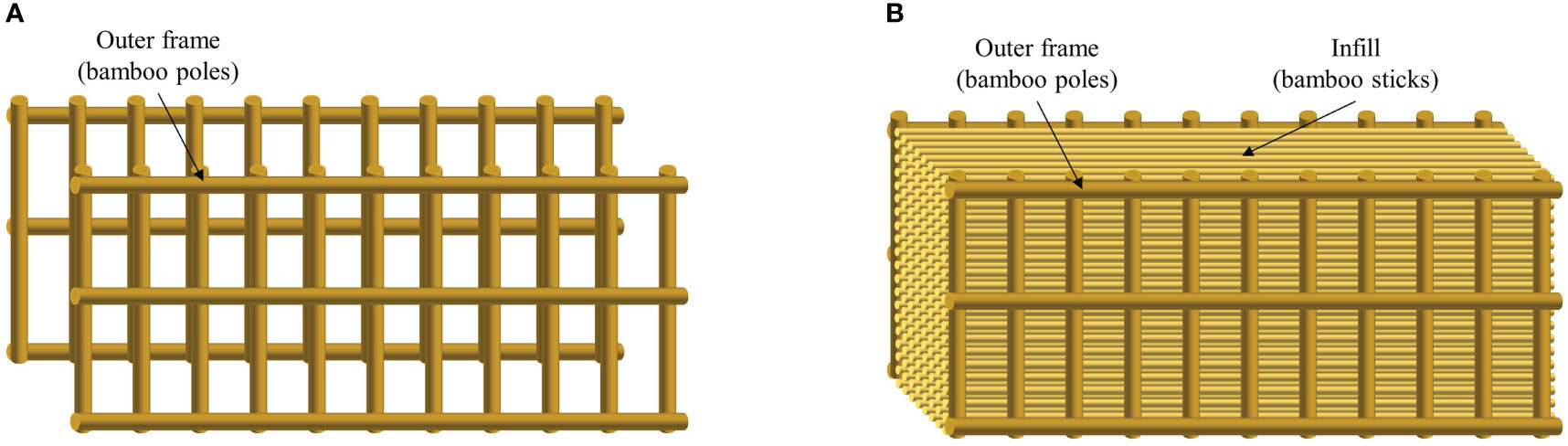
Figure 1 Schematic of two types of bamboo fence (A) without porous infill and (B) with porous infill. Fence model without porous infill. (A) Two densities of frames. (B) One of the fence models without porous infill.
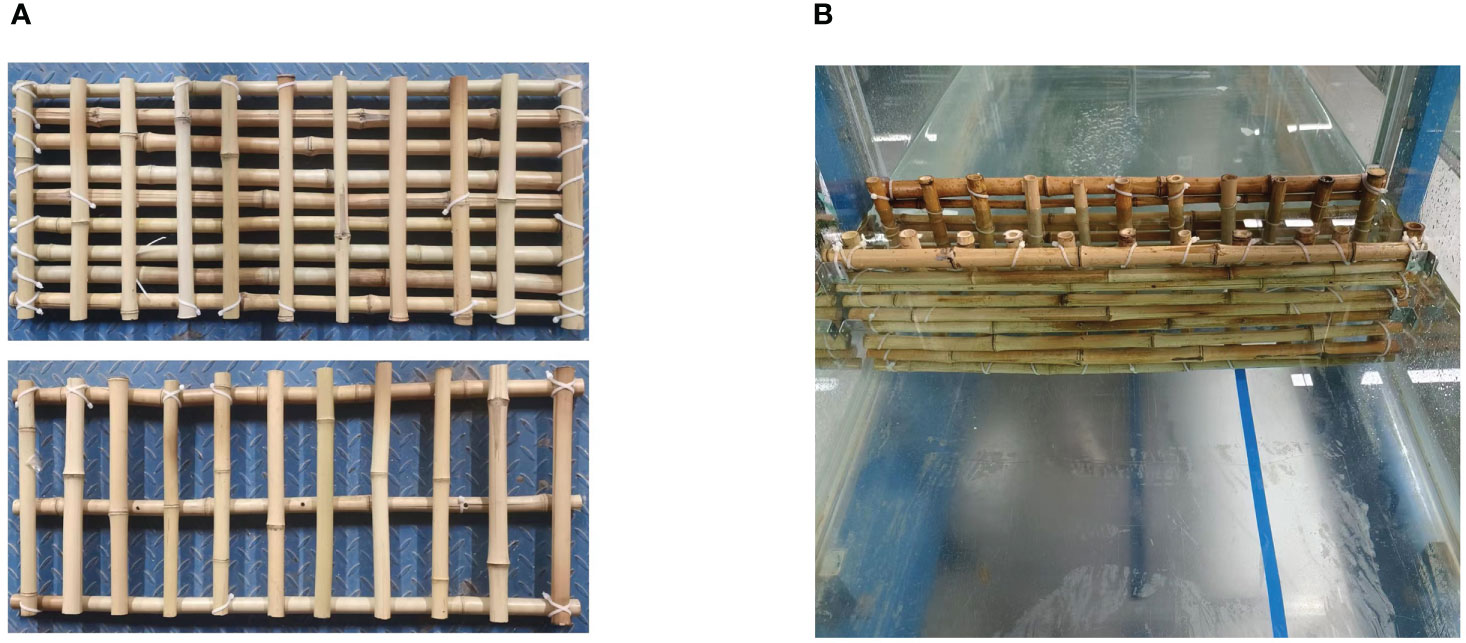
Figure 2 Fence model without porous infill. (A) Two densities of frames. (B) One of the fence models without porous infill.
As for the fence with porous infill, the porous infill inside was made of bamboo sticks with a certain stiffness and placed staggered and perpendicular to the wave direction in the flume (Figure 3). The infill porosity (P) is the ratio of the pore volume to the total volume between the front and rear frames, and it can be predetermined by changing the number and spacing of the bamboo sticks (N and S). A total of four infills with different porosities were made in this experiment, and the porosity was 100% for the fence without infill.
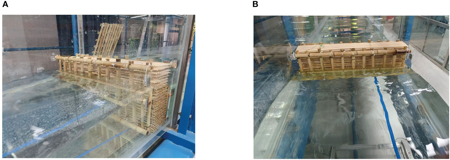
Figure 3 Fence model with porous infill. (A) Infill porosity of 90%. (B) Infill porosity of 60%.
The mimicked prototype configuration was determined based on the practices of Albers et al. (2013) and Thieu Quang and Mai Trong (2020) in the field, where the height of the fence was 1.3 m, the diameter of the bamboo poles was approximately 8 cm, and the diameter of the infill bamboo sticks ranged from 1 to 2 cm. The length scale of the experiment was set to be 1:4; therefore, the physical model used in the experiment has a height of 32.5 cm, an internal width of 12.5 cm, a diameter of approximately 2 cm for the outer bamboo poles (Figure 4A), and a diameter of 0.5 cm for the infill bamboo sticks (Figure 4B). Each fence model had a distinct frame density and infill porosity. The fence model used in the experiment and the characteristics of the infill and frame are discussed in Table 1.
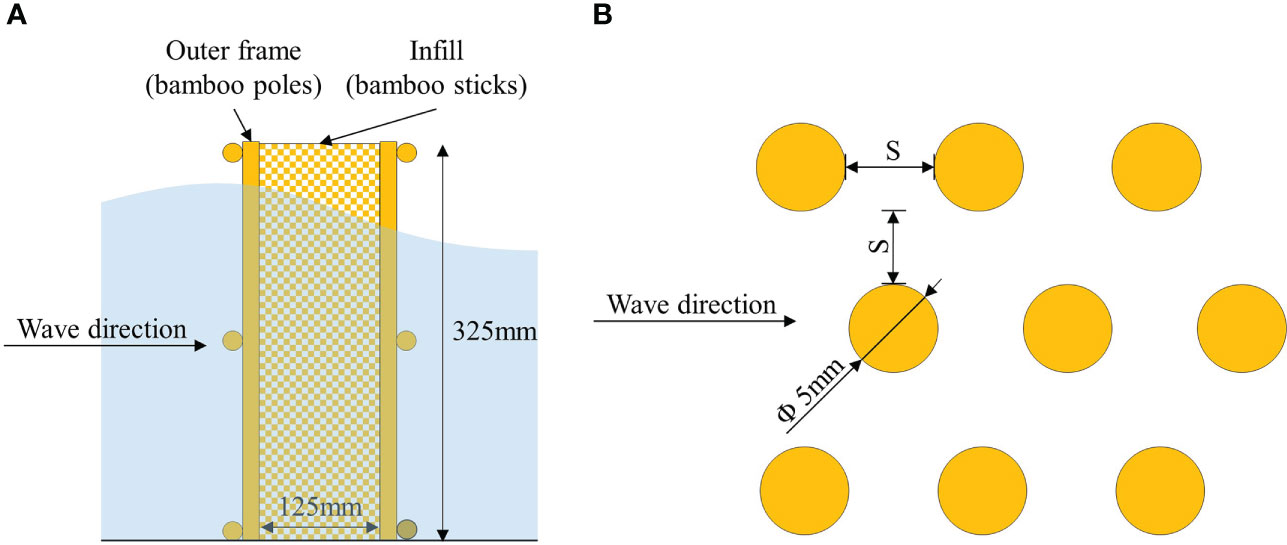
Figure 4 Schematic of bamboo fence (A) and staggered arrangement of infill (B).
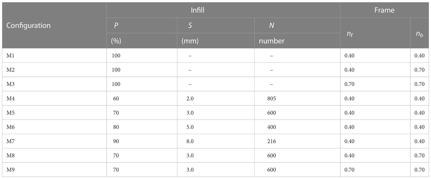
Table 1 Configuration of artificial fences parameterized in the experiment.
2.2 Mathematical description for wave–fence interaction
2.2.1 Wave transformation
The interaction between the wave and the fence during wave progression can be divided into three different processes (Shao, 2005)—frontal reflection, rear transmission, and internal dissipation—resulting in the separation of wave energy into three components during the process: reflected energy (Er), transmitted energy (Et), and dissipation energy (Ed) inside the fence.
Since the energy of a regular wave is proportional to the square of the wave height, it can be described as follows:
where Kt = Ht/Hi is the ratio of the transmitted wave height Ht to the incident wave height Hi, Kr = Hr/Hi is the ratio of the reflected wave height Hr to the incident wave height Hi, and Kd is the square root of the ratio of dissipation energy (Ed) and total wave energy (Ei). To determine the precise ratio of these three types of energy in the experiment, the transmitted wave height Ht and the reflected wave height Hr are measured in front of and behind the fence.
2.2.2 Bulk drag coefficients
To characterize the wave damping performance of fences with porous infills, the bulk drag coefficients (CD) of M4, M5, M6, and M7 were also derived. Considering that the infill bamboo sticks inside the fence in this experiment were placed horizontally, the wave transmission model proposed by Suzuki et al. (2019) accounting for both vertical and horizontal wave forces acting on the cylinders was used here, and the monochromatic wave transmission in a cylinder array with a flat bottom is thus expressed as follows:
With
where Hi is the wave height at the boundary of the cylinders, bv is the stem diameter of the cylinder, Nv is the number of plants per square meter, k is the wavenumber, a is the inundation degree of the vegetation, and d is the water depth. Due to the gradient distribution of wave heights and flow velocities in the vegetation field, the drag coefficients of a single cylinder will vary; thus, the CD used here represents the empirical bulk drag coefficients, and the wave reflection is neglected.
2.3 Experimental setup and wave generation
The wave flume used is located in the State Key Laboratory of Water Environment Simulation at Beijing Normal University, which is 25 m in length and 0.8 m in width. This flume can generate regular or irregular waves with a minimum operating water depth of 0.2 m and a maximum wave height of 0.3 m. There are five digital wave gauges (WG1 → WG5) that can directly generate a digital signal of water level at a maximum sampling frequency of 1,000 Hz and an accuracy of 5‰; the placement of each wave gauge is shown in Figure 5. WG1 is used to control the non-reflected wave maker with an active reflection compensation (ARC) system, and it is located at the front of the tank near the wave paddle. A group of WG2 and WG3 at the front of the model are used to measure the height Hr of the reflected wave; the incoming and reflected waves can be separated by using the method of Goda and Suzuki (1976). Another group of WG4 and WG5 at the rear of the model are placed to monitor the transmitted wave height Ht at the same time.
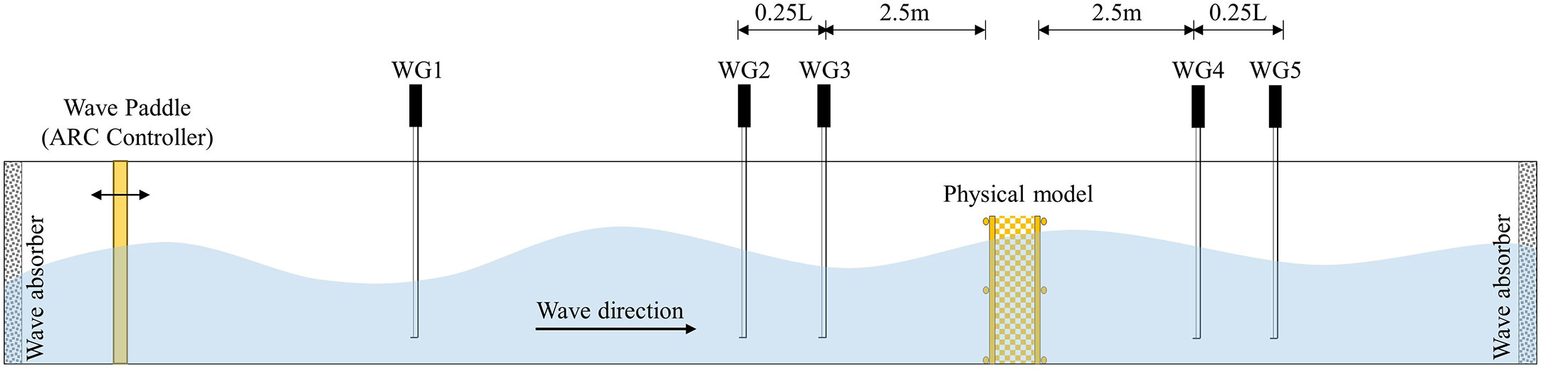
Figure 5 Schematic of the wave flume and experimental setup.
Table 2 presents regular wave conditions generated during the experiment, with water depths of 20, 25, and 30 cm; wave heights of 4, 6, and 8 cm; and wave periods of 1.0, 1.5, and 2.0 s. These artificial waves have water depths less than the fence height without wave overtopping, but there are some cases where the wave crest height exceeds the fence height (d = 0.3 m with Hi = 0.06, 0.08 m).
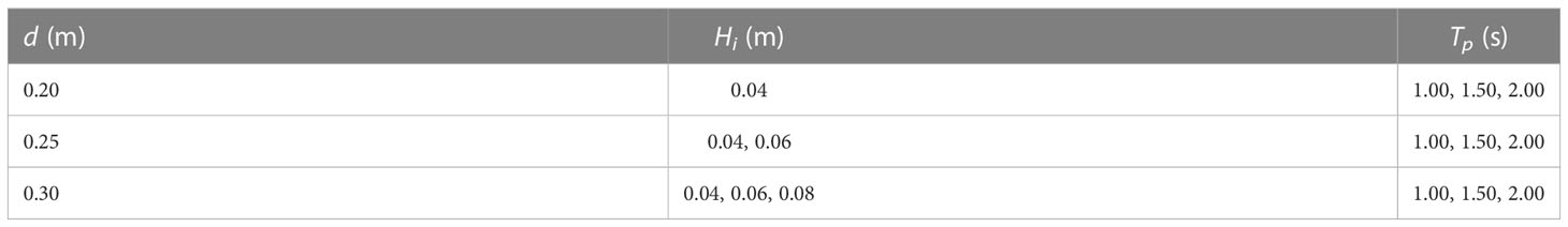
Table 2 Characteristics of regular waves generated in the flume.
3 Results and discussion
3.1 Influence of fence configuration on the wave transmission
3.1.1 Influence of frame density on wave transmission
The density of the external frame, in particular the front frame, is shown to have a direct impact on the wave reflection initiated by the fence structure, which in turn alters the wave-energy dissipation inside the fence and the stability of the structure. Thus, in this section, we focus on the frame density and its related effect on wave transmission. The effect of frame density on the integral wave dissipation performance of the fence with and without porous infill can be well identified by comparing the two sets of fences. The first group includes M1, M2, and M3 and has no infill at all, hence corresponding 100% porosity; but there are differences in the density of the front and rear frames. In the second group (M5, M8, and M9), all frames have 70% infill porosity, and there are also differences in the density of the frames (see Table 1 for details of the density of bamboo poles used in frames of different fences).
It is apparent that the ability of fences to reduce wave energy is influenced by the porous infill (see Figure 6; the hollow symbols represent the wave overtopping), with the transmission coefficient of the fences with porous infill being less than that of fences without infills. For the group without infill, the transmission coefficients of M2 and M3 are lower than those of M1. In the second group with the presence of infill, the transmission coefficients were 0.36–0.79 for M8 and 0.31–0.73 for M9. The differences between the transmission coefficients of fences are invariably small, which indicates that the transmission coefficient is not significantly affected by the density of the frame used in the presence of infill, regardless of whether it is a front or rear frame. Also, for the transmission coefficient, the group of fences without infill experiences a smaller change than the group of fences with porous infill. Moreover, all fence transmission coefficients descend as wave steepness ascends, and this behavior is evident whether wave overtopping occurs or not.
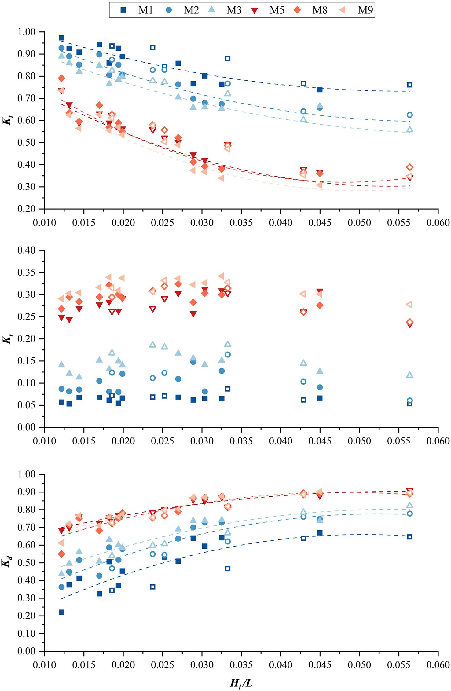
Figure 6 Variation of wave transmission process (quantified using Kt, Kr, and Kd) with wave steepness under the influence of frame density.
As far as wave reflection is concerned, the fence group with porous infills (P = 0.7) produces more reflected wave energy in front of the fence (see Figure 6). For each group, a denser frame tends to create a higher wave reflection coefficient. Compared with the average reflection coefficient of 0.06 of M1, the average reflection coefficients of M2 and M3 in the group of fences without infill range are 0.06 and 0.10, respectively. For the group of fences with infill, the average wave reflection coefficients were 0.29 for M9 and 0.32 for M8, with no significant increase compared to the average wave reflection coefficient of 0.28 for fence M5 with sparse frame density. In addition, regardless of wave overtopping, the wave reflection coefficient of each fence is uncorrelated with wave steepness.
For the group of fences without infill, a denser frame presents a greater dissipation effect (see Figure 6). However, for the fences with infill, the dissipation coefficient of M8 is at 0.55 to 0.89 and that of M9 is at 0.61 to 0.90; the wave dissipation coefficients are nearly identical among M5, M8, and M9, with only minor differences, suggesting the frame has a minor influence on the wave dissipation efficiency of the fence with porous infill. Moreover, the wave dissipation coefficient rises with increasing wave steepness, but the trend slows down gradually.
In general, for the frame density, an increase in the number of bamboo poles used in the frame to enlarge the frontal area can slightly lower the wave transmission coefficients of the fence without infill by approximately 0.08; however, it also results in an increase in the reflection coefficient approximately 0.04, as well as a slight increase in the proportion of wave energy dissipated inside the fence, which is consistent with the results of Nejadkazem and Gharabaghi (2012). For single-row or multi-row wooden poles, wave dissipation mainly relies on vortices generated by the interaction of waves and poles (Zhu, 2011), and an arrangement with denser bamboo poles triggers more vortices and consequently increases wave-energy dissipation as well as reflections at the same time. Moreover, the back row of bamboo poles also suffers the sheltering effect produced by the first row of bamboo poles due to their short distance. Most wave-energy dissipation and reflection took place when a wave passing through the first row of bamboo poles, and then both wave reflection and wave-energy dissipation by the second row of bamboo poles diminish. Therefore, for double rows of bamboo poles, the wave-energy reduction is primarily dependent upon the blockage and associated vortices triggered by bamboo poles by increasing the density especially the first row of bamboo poles, which can be found in the minor differences in wave attenuation performance between fence M2 and M3.
3.1.2 Influence of infill porosity on wave transmission
Increasing the density of the bamboo sticks used inside the fence reduces the internal spacings of the sticks and increases the specific surface area of the infill, resulting in an increase in the wave-energy dissipation rate (Dao et al., 2020), but it also increases the frontal area and enhances wave reflection and flushing in front of the fence; thus, the optimal porosity of the infill still needs to be assessed. In this section, we compared the wave attenuation effect of five different fences that all have the same external frame and different porosities of the infill, with M1 having no porous infill and thus having a porosity of 100%, and M4, M5, M6, and M7 having a gradual increase in the infill porosities (i.e., 60%, 70%, 80%, and 90%), and the number of bamboo sticks used for infill was gradually declining accordingly.
Regardless of whether wave overtopping occurs, the difference in the wave damping effect among different fences follows the same pattern (see Figure 7), showing that reduced infill porosity corresponds to a smaller transmission coefficient and that the transmission coefficient drops by 0.10 as infill porosity decreases by 10%. The wave transmission height behind fence M1 is the highest, indicating that the damping effect is minimal. For fence M7 with 90% porosity, the wave transmission coefficient of the fences with the infill is the largest, ranging from 0.49 to 0.90; as for M6, it ranges from 0.40 to 0.84; and for M5, it varies from 0.34 to 74. The fence M4 shows the best wave damping performance, as the wave transmission coefficients are between 0.26 and 0.64. Furthermore, it is shown that the wave steepness demonstrates a greater impact on the wave transmission coefficient for each fence, with the transmission coefficients for fences with porous infill approximately dropping by 0.40, and the transmission coefficient of M1 without infill has a limited decline range within 0.23.
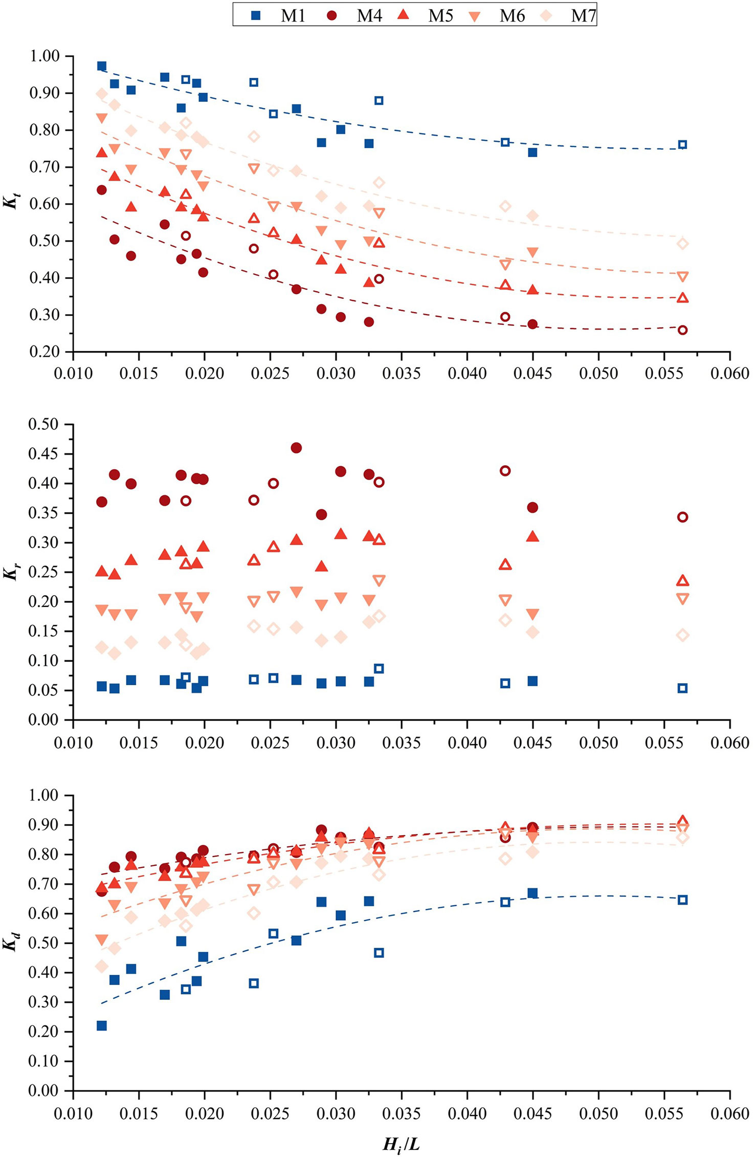
Figure 7 Variation of wave transmission process (quantified using Kt, Kr, and Kd) with wave steepness under the influence of infill porosity.
The wave reflection coefficient in front of M1 is the lowest among these fences due to the lack of infill (less than 0.10) (see Figure 7), indicating that it is experiencing the slightest wave impact. The presence of the infill in other fences caused significant changes in the reflection coefficient, with an evident increase in the reflection coefficient as the infill porosity decreased. To be specific, the average wave reflection coefficients of M5, M6, and M7 are 0.28, 0.20, and 0.14, respectively. M4 has the highest average wave reflection coefficient of 0.39 in front of a fence, indicating that the structure withstood the strongest wave force. It is also found that, regardless of wave overtopping, the wave reflection coefficient of each fence demonstrated no correlation with the wave steepness.
Notably, the calculated wave dissipation coefficients suggest little difference under the different infill porosities (see Figure 7). The wave dissipation coefficient of each fence is positively correlated with the wave steepness, the fence with denser infills is more capable of dissipating incoming wave energy under longer waves, and the discernable difference in the wave dissipation coefficient between each fence is minimal under shorter waves. For instance, wave dissipation coefficient discrepancies between fences M4, M5, and M6 with infill porosities of 60%, 70%, and 80%, respectively, are not as substantial above a certain wave steepness.
In general, for the fence with porous infill, the infill porosity plays a vital role in the wave transmission process. The fence with the lowest frame density and no infill (M1) has a limited ability to attenuate incoming waves with high transmission coefficients (0.76), and the fence with the most porous infill (M7) shows a supportive ability to attenuate incoming waves with lower transmission coefficients (0.49), which was superior to the high-density frame (M3, no infill) in terms of transmission and dissipation coefficients obtained at the same reflection coefficient. Most importantly, in the case of the same frame, the presence of infill can effectively increase the proportion of wave energy dissipated within the fence, but it also inevitably increases the wave reflection strength because of the increase in the frontal area.
Moreover, the presence of infill improves wave-energy dissipation within the bamboo fence, with the underlying mechanism being the same as that of wave transmission through the vegetation field, where the wave received surface friction, drag, and inertial forces in the rigid cylinders and additionally received vertical drag forces when the cylinders were horizontally aligned. For the infill made of bamboo sticks, the wave-height decline was more pronounced in the first few rows of the cylinders, and the infill porosity decrease will directly enlarge the frontal area of the infill in the first place. The reduced spacing between the front row of bamboo sticks produces a stronger flow blockage, which means that the wave reflection and drag force generated by the first row of sticks will be strengthened (Etminan et al., 2019). Because less wave energy was introduced into the cylinders, the performance of the cylinders to dissipate wave energy will therefore be somewhat strengthened (Suzuki et al., 2019). The bamboo sticks used in the infill are spaced at a short distance, and the sticks in the subsequent rows are located in the wake of the front row, which is subject to a strong sheltering effect, and the flow velocity they face decreases and the drag force generated decreases (Gijon Mancheno et al., 2021). Therefore, although reducing the infill porosity will increase the energy dissipation, this increment is quite limited, especially at lower infill porosities, which in turn reduces the wave dissipation effect induced by a single cylinder. Using the ratio of Ed/Ei and (1 − P) to represent the wave-energy dissipation effect produced by a single cylinder of the infill, the result shown in Figure 8 suggests that the infill with the highest porosity has the greatest dissipation efficiency induced by a single cylinder and the difference between the dissipation effects produced by a single cylinder of each infill is greater with shorter waves.
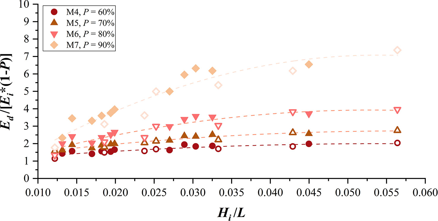
Figure 8 Ratio of Ed/Ei and (1 − P) for fences with different infill porosities versus wave steepness.
Figure 9 shows the calculated results of bulk drag coefficients for the fences with porous infill using Equation 6. Since the wave transmission model ignores the presence of the external frame, which has some geometrical irregularity and impact on the wave attenuation, the calculation results are not fitted well with the Ursell number (Ur), which indicates the non-linearity of the wave. However, when the wave non-linearity increases, the bulk drag coefficients of all four fences decrease, with the bulk drag coefficient of M4, which has the highest density of infill, at 3.0–8.1; M5, 2.9–6.4; M6, 2.2–7.0; and M7, 2.2–8.7. When comparing the four fences under the same wave conditions, it is worth noting that the calculated bulk drag force coefficients for fences M4 and M7 are nearly close, while the calculated results for M5 and M6 are also very similar but smaller than the bulk drag coefficients of fences M4 and M7.
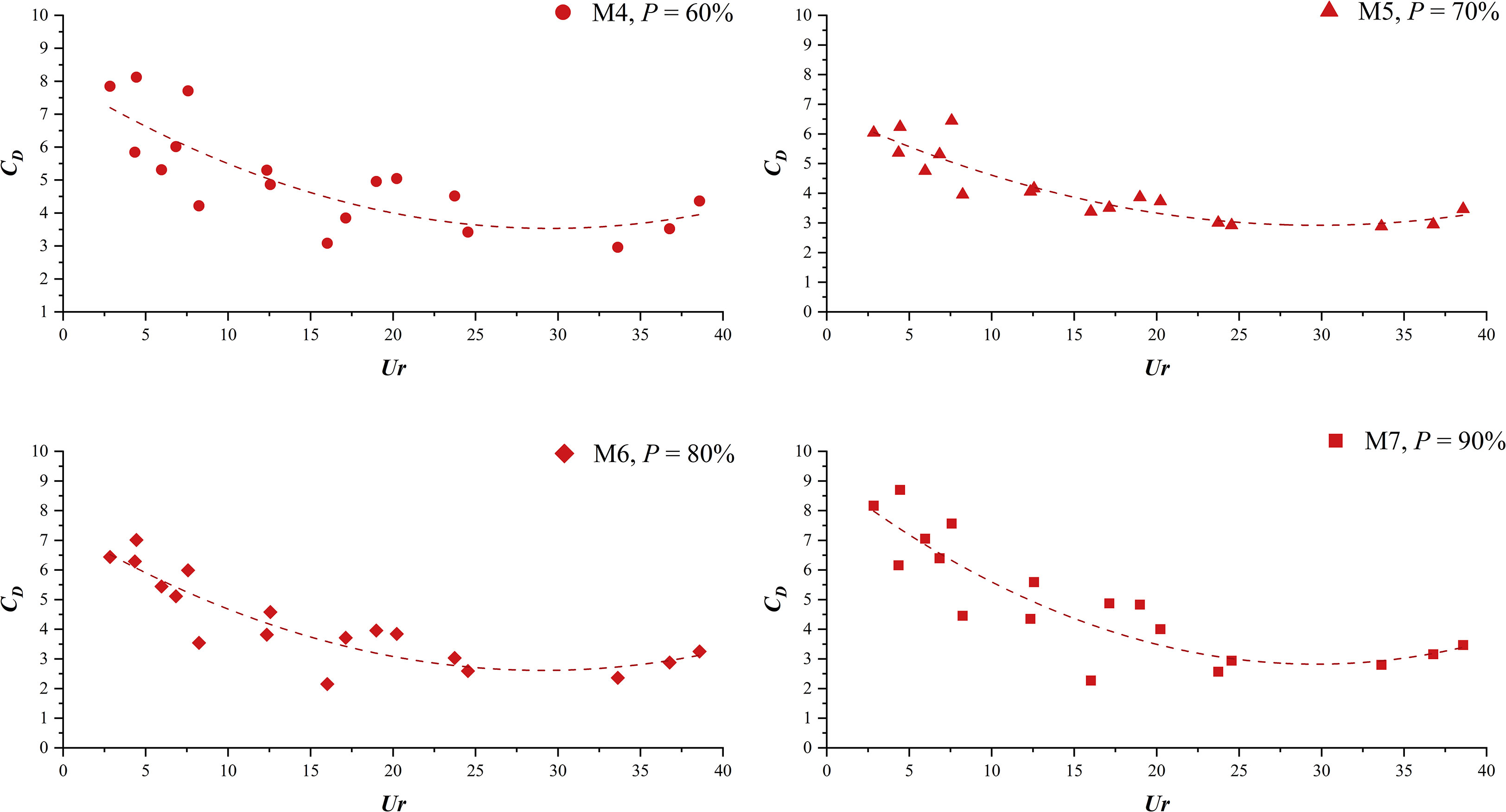
Figure 9 Calculated CD for the fences with different infill porosities.
Since the calculation solely considers wave-energy dissipation inside the cylinder array, which includes the effect of disturbances of the velocity field imposed by drag and inertial forces, it does not consider wave reflection energy produced by cylinders, which were too strong to ignore for infill with lowest porosity (fence M4). Combined with the results of the previous three parts, it is clear that larger bulk drag coefficients are generated by the M4 fence due to the high strong wave reflection at the front of the fence, which leads to a reduction in the wave energy entering the infill. In contrast, the wave reflection produced by M7 is much smaller, and the proportion of wave energy entering the interior of the infill is much larger, indicating a stronger effect of its single infill elements on wave dissipation under similar bulk drag coefficients (see Figure 8). Since part of the inescapable wave energy was reflected, the bulk drag coefficient calculation results of various fences can only represent the wave attenuation or damping effect of the per element of infill and do not account for the actual wave dissipation effect, which may be overestimated.
3.2 Influence of wave characteristics on the wave transmission
In the previous section, the results showed that the incident wave steepness can influence the wave transmission process of the fences; in this section, we will further examine and discuss the impact of wave characteristics on the wave transmission process in terms of still water depth, wave height, and period.
The wave damping performance of the fences is negatively correlated with the still water depth under the same wave height and period (Hi = 0.04 m, T = 1.50 s) (Figure 10). For incident waves with a 10-cm increase in water depth, the wave transmission coefficient of most fences increases by more than 0.1, with fence M4 experiencing the largest increase of 0.15, while the wave reflection coefficients in front of the fence show little change as the water depth increases (Figure 10), which may be because the frontal area of the fence has a major influence on the wave reflection. Since the wave reflection coefficient is essentially stable, an increase in the wave transmission coefficient corresponds to a decrease in the wave dissipation coefficient, with most of the fences having a negative correlation between the wave dissipation coefficient and average water depth (Figure 10).
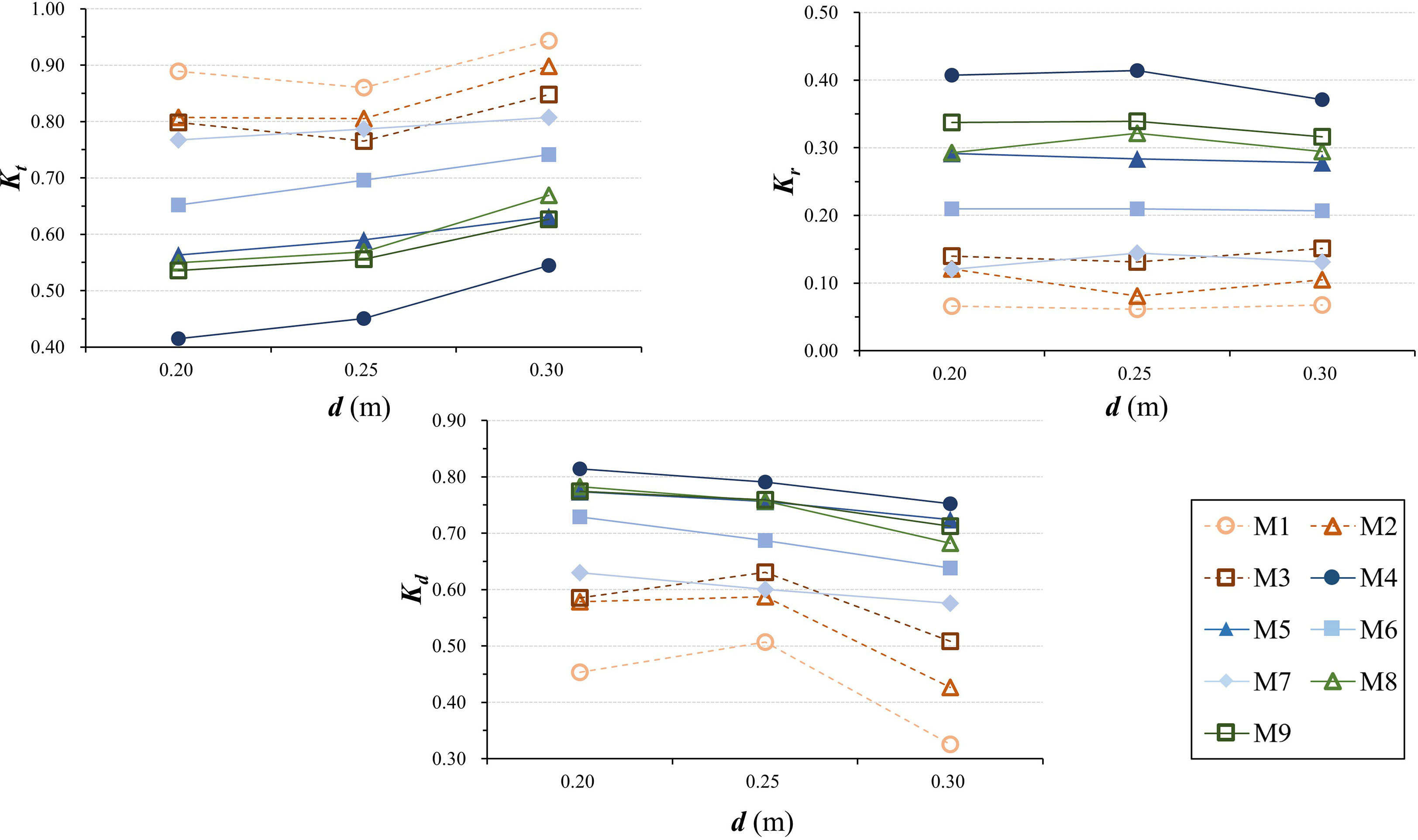
Figure 10 Influence of water depth on the wave transmission process (i.e., Kt, Kr, and Kd).
Compared with the still water depth, the effect of wave height on the wave damping performance of the fences is more significant. Under the same water depth and period (d = 0.30 m, T = 1.50 s), the wave transmission coefficients of almost all fences decrease with the increased wave height (Figure 11), with the most severe decline found for fence M8, reaching 0.18. Despite a drop in wave transmission coefficients, the transmitted wave heights behind the fences at higher incident wave heights remain higher than at lower incident wave heights. Meanwhile, the wave reflection in front of practically all fences tends to increase slightly when wave height increases (Figure 11); however, this increase is typically smaller than 0.05. As a result, the proportion of wave-energy dissipation inside the fence rises significantly (Figure 11), reaching a maximum value of 0.19.
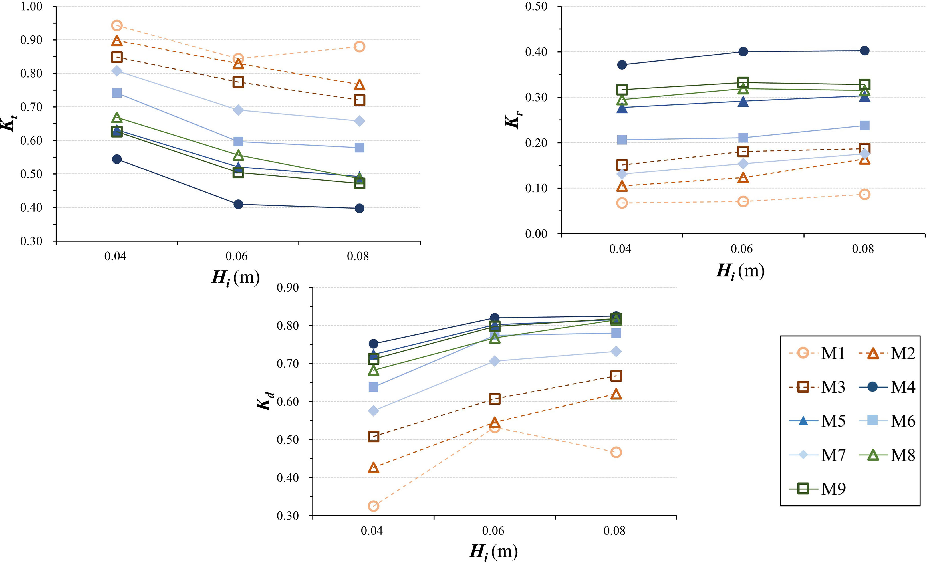
Figure 11 Influence of wave height on the wave transmission process (i.e., Kt, Kr, and Kd).
For the same wave height and water depth (d = 0.20 m, Hi = 0.04 m), the wave damping performance of the fences is noticeably reduced when the incident wave period increases (Figure 12), with the wave transmission coefficient of each fence increasing by more than 0.1. Meanwhile, the wave reflection intensity in front of the fence only slightly increases with an increased wave period (Figure 12). Coupled with the increased transmission coefficient and decreased reflection coefficient, the wave dissipation coefficient shows a decreasing trend (Figure 12), which is more pronounced in the fence without porous infill, while for the fence with infill, the decrease of wave dissipation coefficient becomes greater with increasing porosity.
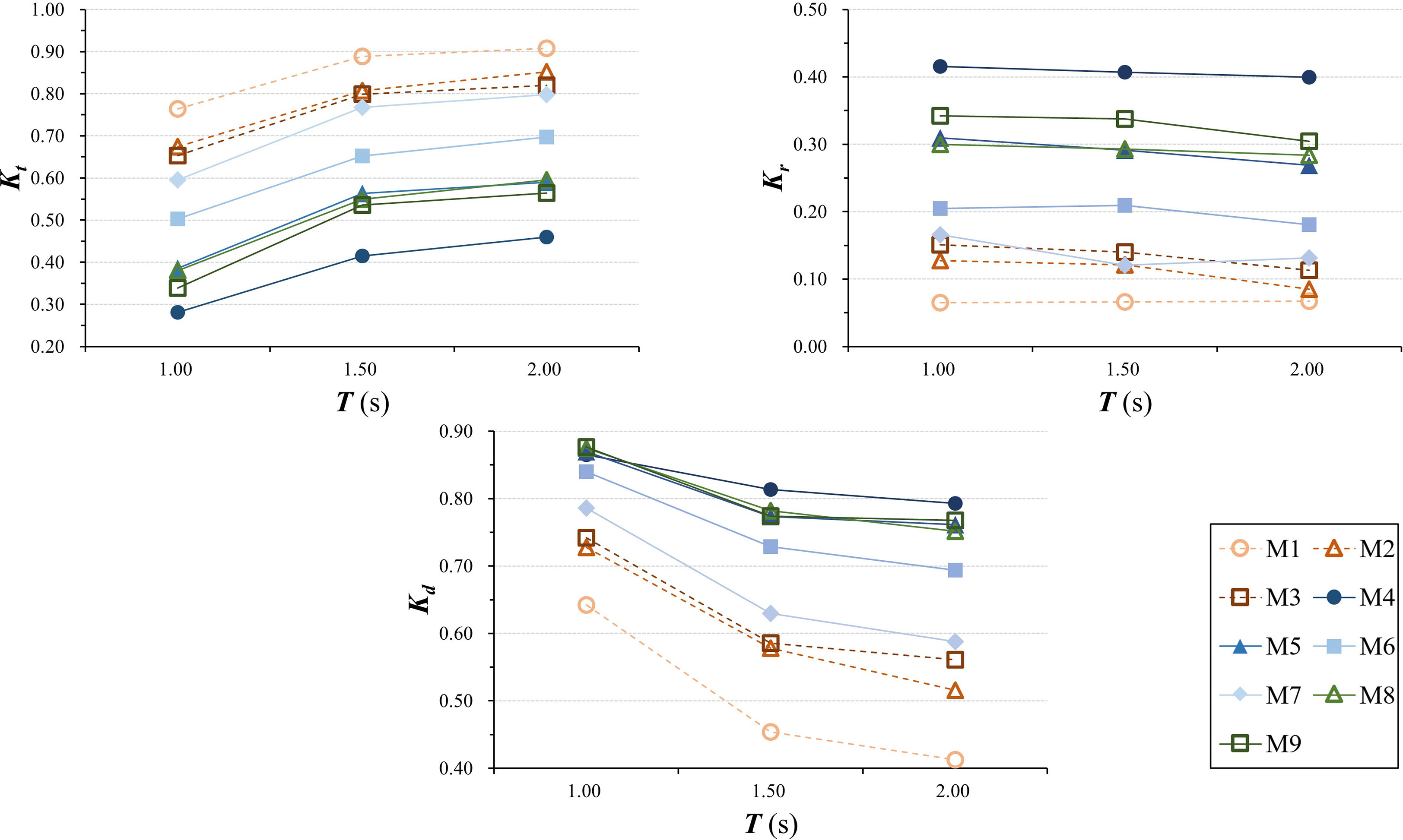
Figure 12 Influence of wave period on the wave transmission process (i.e., Kt, Kr, and Kd).
In general, the mechanism of incident wave characteristics influencing the wave transmission process through fences is attributed to the motion patterns of water particles under complex wave actions. Since the wave steepness is negatively correlated with wave period and still water depth but positively correlated with wave height, and the flow velocity and acceleration increase as wave steepness increases, the interaction between cylinders and the steeper waves can produce more turbulent flow with increased wave height; long waves with smaller wave steepness are more powerful than short waves with shorter periods; the flow between the cylinders become more streamlined (Jansen, 2019), with larger wake areas generated around the elements, indicating a more pronounced sheltering effect. This is consistent with the observation of Thieu Quang and Mai Trong (2020) that low-frequency waves penetrate the fence more easily.
3.3 Empirical equation for wave transmission through the fences
In order to describe the wave transmission through each fence, we build an empirical equation based on a previous formula proposed by Le Xuan et al. (2022). The two main parameters relative crest freeboard (Rc/Hi) and wave steepness (Hi/L) were present in our equation (Equation 7), where Rc is the relative height of fence crest freeboard to the still water level, and (Rc/Hi) is considered to be the correction of the relationship between wave height and crest freeboard.
in which a, b, and c are the empirical constants obtained from linear regression analysis for each fence, and their values correspond to the best correlation coefficient (R2) presented in Table 3.
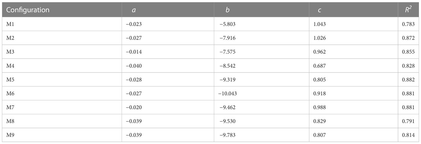
Table 3 Empirical value of constants in Equation 7 for each fence.
3.4 Implications for the optimal design
In the preceding sections, we investigated the wave attenuation performance of two types of fences under a wide range of wave conditions. The fence-covered area in the mangrove restoration site usually has more complex tidal, wave, and substrate characteristics, necessitating effective fence design adjustments. For fences with or without porous infill, it is important to ensure that the height can ensure that the fence is unsubmerged because the submerged state has a significant effect on the wave dissipation effect of the structure, as many studies have confirmed (Gao et al., 2012; Kim et al., 2021); it is also critical to verify that the water level changes in the coastal site match well with the scale of the structure during the design phase. For fences with porous infill, the high density of the infill greatly reduces the transmitted wave height at the back of the fence and increases reflection at the front of the fence, suggesting that it is directly affected by the stronger wave forces, and there is no distinct increase in internal wave-energy dissipation.
In comparison with other permanent constructions, such as breakwater concrete, bamboo fences cannot survive as a non-permanent structure during high wind and strong wave events, and broken bamboo fences could even have a negative effect on coastal zone protection due to the floatable feature of bamboo. A study conducted by Pranchai et al. (2019) confirmed that floating debris originating from coastal bamboo fences and breakwaters in the Gulf of Thailand damaged the trunks of mangrove trees, particularly vulnerable pneumatophores. Furthermore, experimental research (Dao et al., 2021) has confirmed that increasing the width of the fence may not necessarily increase the wave reflection generated by the fence in the case of the same porosity; thus, in mangrove restoration practice, the density of the infill should not be increased alone, which can be maintained at 70%–80%, and the width of the fence should be increased to achieve a better wave damping effect. To provide adequate protection for mangrove seedlings, it is also possible to consider the combination of high-porosity fences and other porous structures, such as rubble mound and oyster reefs. Succinctly, mangrove seedlings are valuable and should be protected from strong waves and sediment flushing. The bamboo fence construction should reduce incident waves while promoting sedimentation on the tidal flats. It should also maintain a certain level of stability to prevent negative effects on the seedlings. To provide the best protection as anticipated, the fence plan or profile arrangement on the tidal flats should be constructed in accordance with the actual hydrodynamic and topographic circumstances of afforestation sites.
4 Conclusion
In this study, two types of artificial fences made of bamboo for mangrove reforestation are investigated through physical model experiments: the first category is designed with only two rows of frames and the second one with porous infill between the two rows of frames. This study highlights the importance of infill and the influence of infill porosity on the wave transmission process, while we also investigate the effect of frame material density on the wave transmission process for a fence without infill. The major conclusion can be described as follows.
The results demonstrate that incident wave characteristics can substantially determine the wave attenuation performance of all fences employed in the present experiment, with an increase in wave height leading to a reduction of the wave transmission coefficient and an increase of the wave dissipation coefficient, but both water depth and period indicate an opposite effect. In general, the wave transmission coefficients of the fences tend to decrease as wave steepness increases, but the wave steepness has a limited impact on wave reflection, which leads to a higher wave-energy dissipation rate inside the fence under shorter waves.
For the fence without infill, a low-density frame with less material has a limited effect on wave attenuation, but a high-density frame with more material improves wave attenuation performance while also leading to an increase in the reflection coefficient and the proportion of wave-energy dissipation inside the fence. In addition, the presence of infill greatly improves the wave attenuation effect generated by the fence, with even the maximum infill porosity (90%) increasing the proportion of wave-energy dissipation inside the fence.
For the fence with porous infill, lower infill porosity reduces transmitted wave height behind the fence, but it also enhances wave reflection in front of the fences, which leads to limited wave energy dissipated inside the fence, resulting in the infill with the higher porosity (90%) having the greater dissipation efficiency induced by a single cylinder, which was more obvious under shorter waves. The difference in the wave dissipation coefficient between fences M4 and M5, which use 60% and 70% porosity infill, respectively, is not obvious. Meanwhile, the influence of frame density on the wave transmission process is quite minor for fences with porous infill.
Based on the results of the current experiment, it is recommended to give more attention to the role of the infill porosity and avoid misleadingly reducing infill porosity to improve wave attenuation performance when using bamboo fences in mangrove restoration practices, as doing so will increase wave reflection and affect the fence stability, as well as negatively impair mangrove seedlings behind the fence. Meanwhile, it is proposed that the performance of bamboo fences in wave attenuation should be further promoted by increasing its width to limit wave reflection and increase the proportion of wave energy dissipated inside the fence (or absorbed by the fence).
Data availability statement
The original contributions presented in the study are included in the article/supplementary material. Further inquiries can be directed to the corresponding authors.
Author contributions
AS was responsible for the framework and design of the experiments, analysis of the results, and conclusions of the paper. JZ performed the experiments, helped with the analysis of the results, and wrote and revised the paper. ZZ and CP analyzed the experimental datasets and wrote the paper. LW and BC revised the paper. All the authors jointly contributed to this research. All authors contributed to the article and approved the submitted version.
Funding
This work was supported financially by the Key Project of the National Natural Science Foundation (Grant No. U1901212) and the Natural Science Foundation of China under Grant Nos. 52009041, 11372048, 52009041.
Conflict of interest
The authors declare that the research was conducted in the absence of any commercial or financial relationships that could be construed as a potential conflict of interest.
Publisher’s note
All claims expressed in this article are solely those of the authors and do not necessarily represent those of their affiliated organizations, or those of the publisher, the editors and the reviewers. Any product that may be evaluated in this article, or claim that may be made by its manufacturer, is not guaranteed or endorsed by the publisher.
References
Albers T., San D. C., Schmitt K. (2013). “Shoreline Management Guidelines: Coastal Protection in the Lower Mekong Delta”, Deutsche Gesellschaft für Internationale Zusammenarbeit (GIZ) GmbH. 1, 1–124. Available online at: https://www.researchgate.net/publication/315637641.
Albers T., Von Lieberman N. (2011). Current and Erosion Modelling Survey. Deutsche Gesellschaft für Internationale Zusammenarbeit (GIZ) GmbH. 1, 1–61. Available online at: http://coastal-protection-mekongdelta.com/download/library/.
Albers T., Schmitt K. (2015). Dyke design, floodplain restoration and mangrove co-management as parts of an area coastal protection strategy for the mud coasts of the Mekong delta, Vietnam. Wetlands Ecol. Manage. 23 (6), 991–1004. doi: 10.1007/s11273-015-9441-3
Armono H. D., Bromo B. H., Sholihin , Sujantoko (2021). Numerical study of bamboo breakwater for wave reduction. Fluids 7 (1), 14. doi: 10.3390/fluids7010014
Atwood T. B., Connolly R. M., Almahasheer H., Carnell P. E., Duarte C. M., Ewers Lewis C. J., et al. (2017). Global patterns in mangrove soil carbon stocks and losses. Nat. Climate Change 7 (7), 523–528. doi: 10.1038/nclimate3326
Augustin L. N., Irish J. L., Lynett P. (2009). Laboratory and numerical studies of wave damping by emergent and near-emergent wetland vegetation. Coast. Eng. 56 (3), 332–340. doi: 10.1016/j.coastaleng.2008.09.004
Balke T., Bouma T. J., Horstman E. M., Webb E. L., Erftemeijer P. L. A., Herman P. M. J. (2011). Windows of opportunity: thresholds to mangrove seedling establishment on tidal flats. Mar. Ecol. Prog. Ser. 440, 1–9. doi: 10.3354/meps09364
Danielsen F., Sorensen M. K., Olwig M. F., Selvam V., Parish F., Burgess N. D., et al. (2005). The Asian tsunami: a protective role for coastal vegetation. Science 310 (5748), 643. doi: 10.1126/science.1118387
Dao H., Hofland B., Stive M., Mai T. (2020). Experimental assessment of the flow resistance of coastal wooden fences. Water 12 (7), 1910. doi: 10.3390/w12071910
Dao H. T., Hofland B., Suzuki T., Stive M.J.F., Mai T., Tuan L.X. (2021). Numerical and Small-scale Physical Modelling of Wave Transmission by Wooden Fences. Journal of Coastal and Hydraulic Structures 1, 4. doi: 10.48438/jchs.2021.0004
Etminan V., Lowe R. J., Ghisalberti M. (2019). Canopy resistance on oscillatory flows. Coast. Eng. 152, 103502. doi: 10.1016/j.coastaleng.2019.04.014
Flores-de-Santiago F., Serrano D., Flores-Verdugo F., Monroy-Torres M. (2017). Application of a simple and effective method for mangrove afforestation in semiarid regions combining nonlinear models and constructed platforms. Ecol. Eng. 103, 244–255. doi: 10.1016/j.ecoleng.2017.04.008
Gao Z. Q., Zhang R. J., Luan S. G., Fu D. W. (2012). Experimental study on regular wave of transmission coefficient through a hollow-block mound breakwater. Appl. Mechanics Materials 170-173, 2200–2203. doi: 10.4028/www.scientific.net/AMM.170-173.2200
Gijón Mancheño A., Jansen W., Uijttewaal W. S. J., Reniers A. J. H. M., van Rooijen A. A., Suzuki T., et al. (2021). Wave transmission and drag coefficients through dense cylinder arrays: implications for designing structures for mangrove restoration. Ecol. Eng. 165, 106231. doi: 10.1016/j.ecoleng.2021.106231
Gijon Mancheno A., Jansen W., Winterwerp J. C., Uijttewaal W. S. J. (2021). Predictive model of bulk drag coefficient for a nature-based structure exposed to currents. Sci. Rep. 11 (1), 3517. doi: 10.1038/s41598-021-83035-0
Goda Y., Suzuki T. (1976). Estimation of incident and reflected waves in random wave experiments. Coast. Eng. Proc. 1 (15), 828–845. doi: 10.9753/icce.v15.47
Jansen W. (2019). Wave dissipation in a permeable structure: experimental research on the physical processes causing energy dissipation inside an array of cylinders, [Master's thesis] (Delft University of Technology). Available online at: http://resolver.tudelft.nl/uuid:acce330d-968a-46a7-853f-73137b06002a.
Kamali B., Hashim R. (2011). Mangrove restoration without planting. Ecol. Eng. 37 (2), 387–391. doi: 10.1016/j.ecoleng.2010.11.025
Kazemi E., Tait S., Shao S. (2020). SPH-based numerical treatment of the interfacial interaction of flow with porous media. Int. J. Numerical Methods Fluids 92 (4), 219–245. doi: 10.1002/fld.4781
Kim T., Kwon Y., Hong S., Kim J., Kwon S., Lee J. (2021). Wave attenuation analysis for artificial coral reefs using a physical modelling approach. J. Coast. Res. 114 (sp1), 529–533. doi: 10.2112/jcr-si114-107.1
Kristensen E., Bouillon S., Dittmar T., Marchand C. (2008). Organic carbon dynamics in mangrove ecosystems: a review. Aquat. Bot. 89 (2), 201–219. doi: 10.1016/j.aquabot.2007.12.005
Leung J. Y., Cheung N. K. (2017). Can mangrove plantation enhance the functional diversity of macrobenthic community in polluted mangroves? Mar. pollut. Bull. 116 (1-2), 454–461. doi: 10.1016/j.marpolbul.2017.01.043
Lewis R. R. (2005). Ecological engineering for successful management and restoration of mangrove forests. Ecol. Eng. 24 (4), 403–418. doi: 10.1016/j.ecoleng.2004.10.003
Le Xuan T., Le Manh H., Ba H. T., Van D. D., Duong Vu H. T., Wright D., et al. (2022). Wave energy dissipation through a hollow triangle breakwater on the coastal Mekong delta. Ocean Eng. 245, 110419. doi: 10.1016/j.oceaneng.2021.110419
Li J., Liu H., Gong K., Tan S., Shao S. (2012). SPH modeling of solitary wave fissions over uneven bottoms. Coast. Eng. 60, 261–275. doi: 10.1016/j.coastaleng.2011.10.006
Luther D. A., Greenberg R. (2009). Mangroves: a global perspective on the evolution and conservation of their terrestrial vertebrates. BioScience 59 (7), 602–612. doi: 10.1525/bio.2009.59.7.11
Mai Van C., Ngo A., Mai T., Dao H. T. (2021). Bamboo fences as a nature-based measure for coastal wetland protection in Vietnam. Front. Mar. Sci. 8. doi: 10.3389/fmars.2021.756597
Marois D. E., Mitsch W. J. (2015). Coastal protection from tsunamis and cyclones provided by mangrove wetlands – a review. Int. J. Biodiversity Science Ecosystem Serv. Manage. 11 (1), 71–83. doi: 10.1080/21513732.2014.997292
Mcleod E., Chmura G.L., Bouillon S., Salm R., Björk M., Duarte C.M., et al (2011). AA blueprint for blue carbon: toward an improved understanding of the role of vegetated coastal habitats in sequestering CO2. Front Eco Environ. 9 (10), 552–560. doi: 10.1890/110004
Mendez F. J., Losada I. J. (2004). An empirical model to estimate the propagation of random breaking and nonbreaking waves over vegetation fields. Coast. Eng. 51 (2), 103–118. doi: 10.1016/j.coastaleng.2003.11.003
Nejadkazem O., Gharabaghi A. R. M. (2012). Mathematical model for hydrodynamic behavior of an array of vertical cylindrical piles used as a breakwater. J. Coast. Res. 28 (6), 1446–1461. doi: 10.2112/jcoastres-d-11-00155.1
Nguyen T. P., Parnell K. E. (2017). Gradual expansion of mangrove areas as an ecological solution for stabilizing a severely eroded mangrove dominated muddy coast. Ecol. Eng. 107, 239–243. doi: 10.1016/j.ecoleng.2017.07.038
Pranchai A., Jenke M., Berger U. (2019). Well-intentioned, but poorly implemented: debris from coastal bamboo fences triggered mangrove decline in Thailand. Mar. pollut. Bull. 146, 900–907. doi: 10.1016/j.marpolbul.2019.07.055
Robertson A. I., Duke N. C. (1987). Mangroves as nursery sites: comparisons of the abundance and species composition of fish and crustaceans in mangroves and other nearshore habitats in tropical Australia. Mar. Biol. 96 (2), 193–205. doi: 10.1007/bf00427019
Saengsupavanich C. (2013). Erosion protection options of a muddy coastline in Thailand: stakeholders’ shared responsibilities. Ocean Coast. Manage. 83, 81–90. doi: 10.1016/j.ocecoaman.2013.02.002
Shao S. (2005). SPH simulation of solitary wave interaction with a curtain-type breakwater. J. Hydraulic Res. 43 (4), 366–375. doi: 10.1080/00221680509500132
Simard M., Fatoyinbo L., Smetanka C., Rivera-Monroy V. H., Castañeda-Moya E., Thomas N., et al. (2018). Mangrove canopy height globally related to precipitation, temperature and cyclone frequency. Nat. Geosci. 12 (1), 40–45. doi: 10.1038/s41561-018-0279-1
Stive M. J. F., Dao T., Hofland B., Mai T. (2018). Wave damping due to wooden fences along mangrove coasts. J. Coast. Res. 34 (6), 1317–1327. doi: 10.2112/jcoastres-d-18-00015.1
Suzuki T., Hu Z., Kumada K., Phan L. K., Zijlema M. (2019). Non-hydrostatic modeling of drag, inertia and porous effects in wave propagation over dense vegetation fields. Coast. Eng. 149, 49–64. doi: 10.1016/j.coastaleng.2019.03.011
Thieu Quang T., Mai Trong L. (2020). Monsoon wave transmission at bamboo fences protecting mangroves in the lower mekong delta. Appl. Ocean Res. 101, 102259. doi: 10.1016/j.apor.2020.102259
Tran L. X., Fischer A. (2017). Spatiotemporal changes and fragmentation of mangroves and its effects on fish diversity in Ca mau province (Vietnam). J. Coast. Conserv. 21 (3), 355–368. doi: 10.1007/s11852-017-0513-9
Van Cuong C., Brown S. (2012) Coastal Rehabilitation and Mangrove Restoration using Melaleuca Fences. Deutsche Gesellschaft für Internationale Zusammenarbeit (GIZ) GmbH 1, 1–26. Available online at: http://coastal-protection-mekongdelta.com/download/library/.
Van Cuong C., Brown S., To H. H., Hockings M. (2015). Using melaleuca fences as soft coastal engineering for mangrove restoration in kien giang, Vietnam. Ecol. Eng. 81, 256–265. doi: 10.1016/j.ecoleng.2015.04.031
Van der Stocken T., Carroll D., Menemenlis D., Simard M., Koedam N. (2019). Global-scale dispersal and connectivity in mangroves. Proc. Natl. Acad. Sci. U.S.A. 116 (3), 915–922. doi: 10.1073/pnas.1812470116
Van Loon A. F., Te Brake B., Van Huijgevoort M. H., Dijksma R. (2016). Hydrological classification, a practical tool for mangrove restoration. PloS One 11 (3), e0150302. doi: 10.1371/journal.pone.0150302
van Wesenbeeck B. K., Wolters G., Antolinez J. A. A., Kalloe S. A., Hofland B., de Boer W. P., et al. (2022). Wave attenuation through forests under extreme conditions. Sci. Rep. 12 (1), 1884. doi: 10.1038/s41598-022-05753-3
Winterwerp J. C., Erftemeijer P. L. A., Suryadiputra N., van Eijk P., Zhang L. (2013). Defining eco-morphodynamic requirements for rehabilitating eroding mangrove-mud coasts. Wetlands 33 (3), 515–526. doi: 10.1007/s13157-013-0409-x
Yanagisawa H., Koshimura S., Miyagi T., Imamura F. (2010). Tsunami damage reduction performance of a mangrove forest in banda aceh, Indonesia inferred from field data and a numerical model. J. Geophysical Res. 115 (C6), C06032. doi: 10.1029/2009jc005587
Keywords: mangroves, mangrove restoration, wooden fence, wave transmission, wave damping, physical modeling
Citation: Shu A, Zhu J, Cui B, Wang L, Zhang Z and Pi C (2023) Coastal wave-energy attenuation by artificial wooden fences deployed for mangrove restoration: an experimental study. Front. Mar. Sci. 10:1165048. doi: 10.3389/fmars.2023.1165048
Received: 13 February 2023; Accepted: 24 April 2023;
Published: 12 May 2023.
Edited by:
Paolo Ciavola, University of Ferrara, ItalyReviewed by:
Songdong Shao, Dongguan University of Technology, ChinaOnrizal Onrizal, University of North Sumatra, Indonesia
Copyright © 2023 Shu, Zhu, Cui, Wang, Zhang and Pi. This is an open-access article distributed under the terms of the Creative Commons Attribution License (CC BY). The use, distribution or reproduction in other forums is permitted, provided the original author(s) and the copyright owner(s) are credited and that the original publication in this journal is cited, in accordance with accepted academic practice. No use, distribution or reproduction is permitted which does not comply with these terms.
*Correspondence: Anping Shu, shuap@bnu.edu.cn; Jiapin Zhu, 202021180067@mail.bnu.edu.cn; Le Wang, lewang@ncepu.edu.cn