Numerical and experimental investigations of hydrodynamics of a fully-enclosed pile-net aquaculture pen in regular waves
 Yong Cui
 Gang Wang
 Chang-tao Guan
- Yellow Sea Fisheries Research Institute, Chinese Academy of Fishery Sciences, Qingdao, China
Large-scale aquaculture pen is one of the essential modes of offshore aquaculture being explored in recent years. In contrast to cage farming, the advantages are more significant as the larger cultural space for fish swimming, the closer-to-nature environment, and the improved ecological quality of fish. As a novel offshore aquaculture structure, fully-enclosed pile-net aquaculture pens (FPAPs) are generally deployed in exposed oceans, where severe waves and currents are of great dominance. The hydrodynamic characteristics of FPAPs in offshore areas deserve further investigation. In this paper, the numerical model of a typical FPAP in waves is proposed based on the finite element method (FEM), then wave loads on and induced motion responses of the FPAP are analyzed. The results show that the maximum loads on the structure and the maximum displacement of piles are closely proportional to the wave height. Secondly, the maximum stress of nets decreases as the embedded depth increases, while the deformation of nets tends to rise with the increase of pile spacing. At last, several structural optimal patterns are given to improve the safety of pen facilities. This work has laid a solid scientific foundation for designs and optimizations of FPAPs in the future.
1 Introduction
Mariculture in China mainly consists of land-based and nearshore aquaculture, and these cultural regions considerably suffer from land-based pollution. Nevertheless, due to economic and social development as well as people’s higher requirements on life, the space available for mariculture has been severely squeezed, resulting in increasingly prominent problems such as excessive farming density, frequent occurrence of diseases and environmental degradation. In order to realize the sustainable development of mariculture and reduce the impact of farming on coastal areas, it is urgent to expand the space for aquaculture and carry out offshore farming (Chu et al., 2020). The large-scale pile-net aquaculture pen is developed as one of the essential innovative modes, suitable for economic fish farming in China. Ordinarily located at the flat seabed with the continental shelves, the primary structures of large-scale aquaculture pens are composed of piles, side nets, rope constraints and affiliated facilities. It can be categorized into two typical types: Coast-connected pile-net aquaculture pen (CPAP, Figure 1A) and fully-enclosed pile-net aquaculture pen (FPAP, Figure 1B), of which the latter would suffer from severe sea states in offshore regions. Due to the shortage of systematic research on FPAPs, the structural design and engineering technology of large-scale pens are still nonetheless immature, and the abilities of anti-stormy waves need to be evaluated and then improved considerably. Therefore, it is universally recognized that hydrodynamic characteristics of the FPAP in waves have become a critical safety issue.
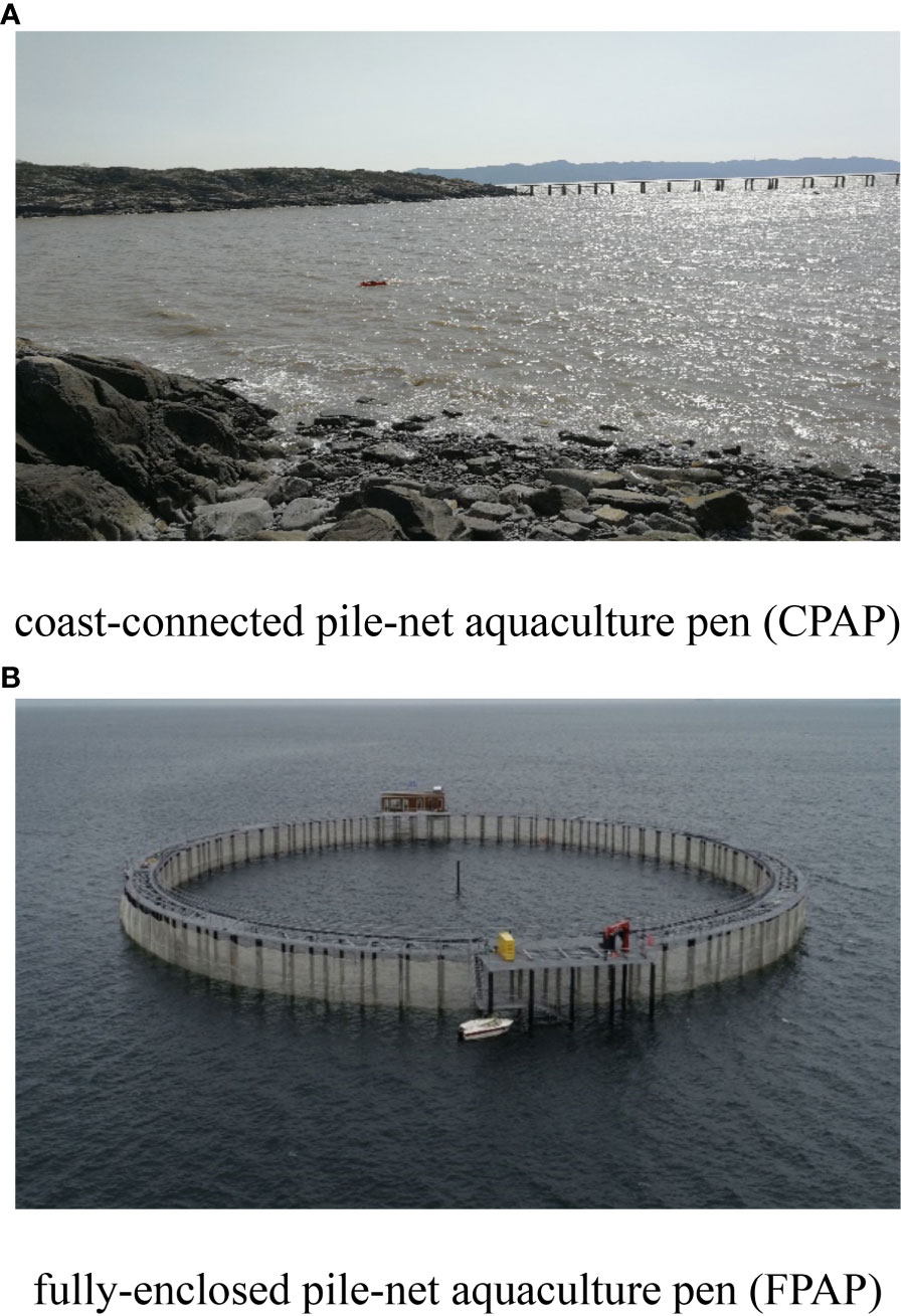
Figure 1 The categories of the large-scale aquaculture pens. (A) coast-connected pile-net aquaculture pen (CPAP). (B) fully-enclosed pile-net aquaculture pen (FPAP).
Without bottom nets and mooring systems, steel piles and side nets assembled in FPAPs have fully formed the cultural regions, indicating that side nets take an indispensable role in the whole aquaculture system. Nevertheless, flexible nets are the most fragile parts compared with piles in open oceans, hence numerous researches related to hydrodynamics of flexible nets have been conducted through model tests and numerical simulation in the past decades. Huang et al. (2018) established a numerical model to simulate the dynamic behavior of a floating net cage in waves and currents, based on the finite element method (FEM). Zhao et al. (2015) conducted a series of physical model experiments to investigate the hydrodynamic characteristics of a large fish farm containing one up to eight net pens with a scaling of 1:40. Cifuentes and Kim (2017) presented an analysis of a cage under combinations of current and wave loading, and the numerical results were validated with experimental data. Bi et al. (2013) conducted a series of laboratory experiments to investigate the reduction in flow velocity downstream from a fishing net in a current. Cui et al. (2014) presented a simulation model based on FEM to analyze the motion response and mooring line tension of a flatfish cage system in waves. Gharechae and Ketabdari (2020) developed a semi-analytical model to find the vertical motions and wave fields around elastic circular floaters of aquaculture fish cages in regular waves. Mohapatra et al. (2021) developed a mathematical model associated with wave interaction with a moored floating flexible cylindrical net cage based on linearized water wave theory. The analytical solution was obtained using the Fourier Bessel series solution and least squares approximation method along with matching the velocity and pressure at the fluid-structure interfaces. He et al. (2018) studied the influence of fish on the mooring loads of a floating net cage.
Initialized from pile-net coupled structures, Yang et al. (2020) investigated the hydrodynamic responses of a floating rope enclosure with different mooring systems in combined wave-current. Gui et al. (2020) and Chen et al. (2018) introduced a novel pile-column type net enclosure, which was mainly composed of piles and net panels. The mechanical properties of nets in waves and current were further investigated using FEM simulation, thereby the guidelines of design and construction have been provided. Zhao et al. (2022) reported a trestle-netting enclosure aquaculture facility combining an offshore steel trestle with a marine aquaculture facility in which the trestle acts as a supporting substructure. A full-scale finite element model of the system was established, then the structural responses subjected to wave were discussed innovatively.
To the authors’ best knowledge, the hydrodynamic characteristics of FPAPs in waves are seldom studied systematically at present. The investigated case of FPAPs adopted in this study is “Lan-zuan No. 1” located in Laizhou Bay of China, which is mainly made up of steel pipe piles, with a volume of 160,000 m3. It is justified in the field monitoring that the existence of deformations and vibrations in waves, threatening long-term safe operations. The hydrodynamic responses of the FPAP in waves are carried out through FEM and experimental validations. Thereby the crucial innovative significance of this study lies in filling the research gap, proposing the design or optimization recommendations from the perspectives of hydrodynamics.
2 Material and methods
2.1 Numerical methods
2.1.1 Finite element methods
The governing equations of dynamic responses of steel frames and nets in waves and currents are defined as follows (Tsukrov et al., 2003):
where M denotes the mass matrix, while K represents the stiffness matrix in the dynamic structural system. Resulting from the relative motion between structures and fluids, F(t) represents the resultant nodal forces including hydrodynamic forces, gravity and buoyancy forces. denotes the nodal displacement vectors, and are the vectors of nodal velocity and acceleration, respectively. The numerical solution to in Eq. (1) is the typical Newmark- time-advancement scheme. The governing equations as well as the detailed schemes have been implemented in the FEM parts of the commercial software ANSYS, of which modelling accuracies have been successfully validated in the flat-cage hydrodynamics investigations (Cui et al., 2013).
The pipe piles, net systems as well as beams are simulated using the PIPE element, with the capabilities of tension-compression, torsion, and bending. The applicability and accuracy of the PIPE element to simulate the hydrodynamics of nets and beams in waves and currents have been justified in Cui et al. (2013). The Morison model is further utilized to calculate the wave loads Fh on piles, nets and beams, which is given by
where denotes the normal drag coefficient while represents the tangential component. denotes the inertia coefficient which is the addition of 1 and the added mass coefficient. is the water density. d and l correspond to the diameters and lengths, respectively. are the velocity vectors of relative motions between water particles and elements, while represents the acceleration vectors. The operational platform made of moderately-thick shell structures is modelled by the SHELL element, with linear, large rotation, and/or large strain non-linear properties (ANSYS Inc, 2009). It is the four-node element capable of simulating six degrees of freedom at each node, thus being widely applied in mechanics studies of offshore structures (Xia et al., 2019). In addition, COMBIN non-linear spring element is adopted to model elastic-plastic soil axial and lateral friction behavior, then the reaction force of soil on the pipe pile can be derived.
2.1.2 Mesh-grouping strategy
The computational loads can be excessively considerable in case of modelling with the actual number of meshes, resulting in the decrease of computational efficiencies. Therefore, a novel mesh-grouping method is utilized for the simplification of all net meshes. Proposed by Wan et al. (2007), the mesh-grouping strategy is to combine several original actual meshes into one so-called virtual mesh. The computational accuracies and efficiencies with various mesh-grouping strategies are discussed, combined with several hypotheses practically. That is, the geometric scale, the weights as well as the hydrodynamics loads should be kept consistent amongst the virtual mesh and the pre-merged meshes during mesh-grouping. It has been widely verified for FEM modelling of net cages and fishing gears in waves and currents (Bi et al., 2014; Cui et al., 2014; Huang et al., 2019), along with the Morison force model. Depicted through continuous bolded lines in Figure 2, the example of a virtual mesh is surrounded by certain physical meshes transversely and longitudinally.
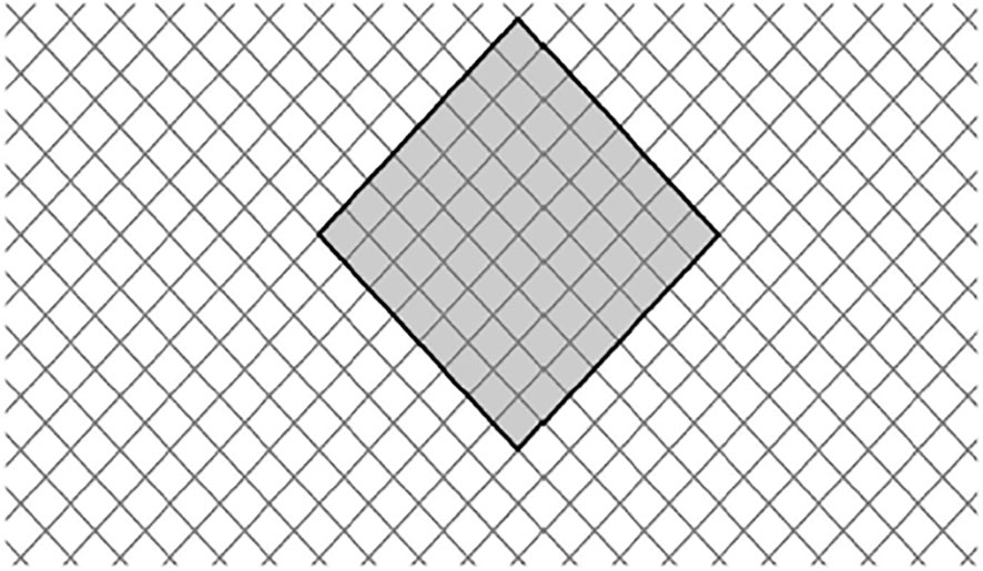
Figure 2 Overview of the grouped mesh.
Keeping the hydrodynamic loads on the virtual mesh and the pre-merged meshes consistent, the relevance of twine diameters can be derived with Morison force model as follows:
Keeping the physical weights of the virtual mesh and the pre-merged meshes consistent, the material densities of twines can be derived as follows:
where NN1 and NN2 are the numbers of longitudinal meshes during grouping, respectively; NT1, NT2 are the numbers of mesh in radial direction during grouping; n denotes the number of the grouping, that is, the number of the actual mesh bar contained in a grouped mesh bar; and are the twine diameter and density of physical meshes, respectively; and are the twine diameter and density of the grouped meshes, respectively.
2.1.3 Pipe-soil interaction model
The overall model restricts the freedom of Z direction (vertical direction) at the bottom node of the pile. In this model, the resistance of soil to pipe pile is simulated by setting p-y parameter of spring elements. Meanwhile, one end of the spring is connected to the pipe pile, and the other end is fully constrained. The constraint mode of the overall model of FPAP is shown in Figure 3.

Figure 3 Overall model constraints.
The formula for calculating the p-y curve of pipe pile located in sandy soil is as follows (Zhao et al., 2007):
where is the horizontal soil resistance acting on unit area of pile side at a certain depth ; is the horizontal displacement at a certain depth is the ultimate soil resistance per unit pile length; is the coefficients; is the initial modulus; is the pile diameter.
2.2 Geometries of “Lan-zuan No.1” FPAP
The large-scale FPAP “Lan-zuan No.1” is mainly composed of pipe piles, nets, an operational platform and beams (see Figure 1B). The perimeter of steel FPAP is 400 m, of which the cultural area is 12,661 m2, and the cultural volume is 160,000 m3. The pen comprises 172 pipe piles, including one central pile and 171 circular pipe piles. The pipe pile uses spiral steel tubes with the diameter of 508 mm and wall thickness of 10 mm. Each pipe pile has a length of 26 m and is welded by two steel tubes of 13 m. The length of the pipe pile inserted into the seabed is 8.5 m. At low tide, the pipe pile is 5.1 m above the water level, and at high tide, it is 4.0 m above the water level. The pen is a structure of double-layer pipe piles, with the diameter of outer piles 127 m and inner piles 117 m. The distance between the inner and outer pipe piles is 5 m. The spacing of external pipe piles is also about 5 m. And the top layer of pipe piles is connected by “N” type beams. The scale of the corridor width is 1250 mm.
2.3 Numerical model of FPAP and cases set-up
The XY plane of the coordinate system is consistent with the horizontal plane. The Z-axis is determined by the right-hand rule and is compatible with the axis of the pipe pile. And the origin of coordinates is located at the center of the FPAP as well as the numerical model are depicted in Figure 4. The input wave scenarios, based on the fifth-order Stokes waves theory, are set based on the actual sea-state data, as described in Table 1.

Figure 4 Overview of finite element models of the FPAP.
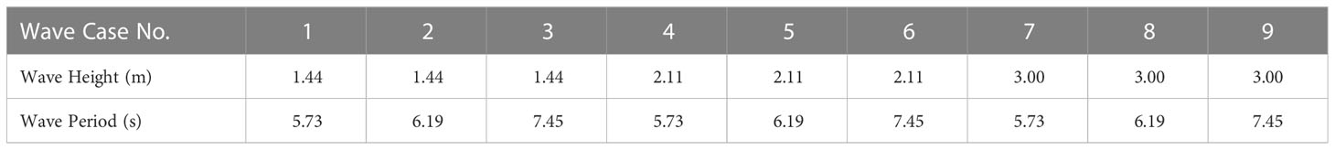
Table 1 Wave cases for the FPAP.
3 Experimental validations
The local model tests were performed in a wave–current flume at the State Key Laboratory of Coastal and Offshore Engineering, Dalian University of Technology, Dalian, China. In order to project the hydrodynamics of the local model into a full-scale one at the large extent, the prototype FPAP have been extracted locally and then scaled to meet the flume test conditions (the test flume is 60.0 m long, 2.0 m wide while the depth corresponds to 1.8 m) using Froude scaling criterion (1:20). In general, the heights and the diameters of pipe piles are 875 mm and 25 mm, respectively (see Figure 5).
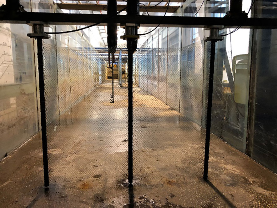
Figure 5 Local physical model test with scale of 1:20.
In order to study the effects of pile spacing on wave force of the pen, three models with pile spacing of 250mm, 500mm and 750mm are tested respectively. The local model and prototype parameters are shown in Table 2. The schematic diagram of three finite element models with different pile spacing is shown in Figure 6.
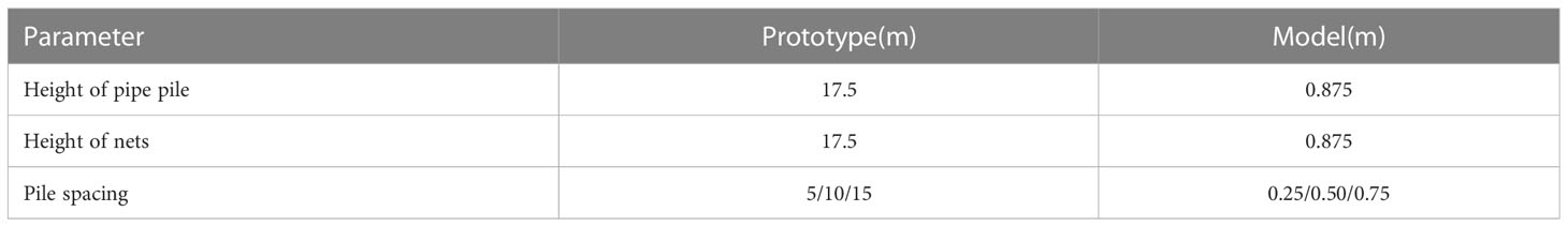
Table 2 Local model and prototype parameters.
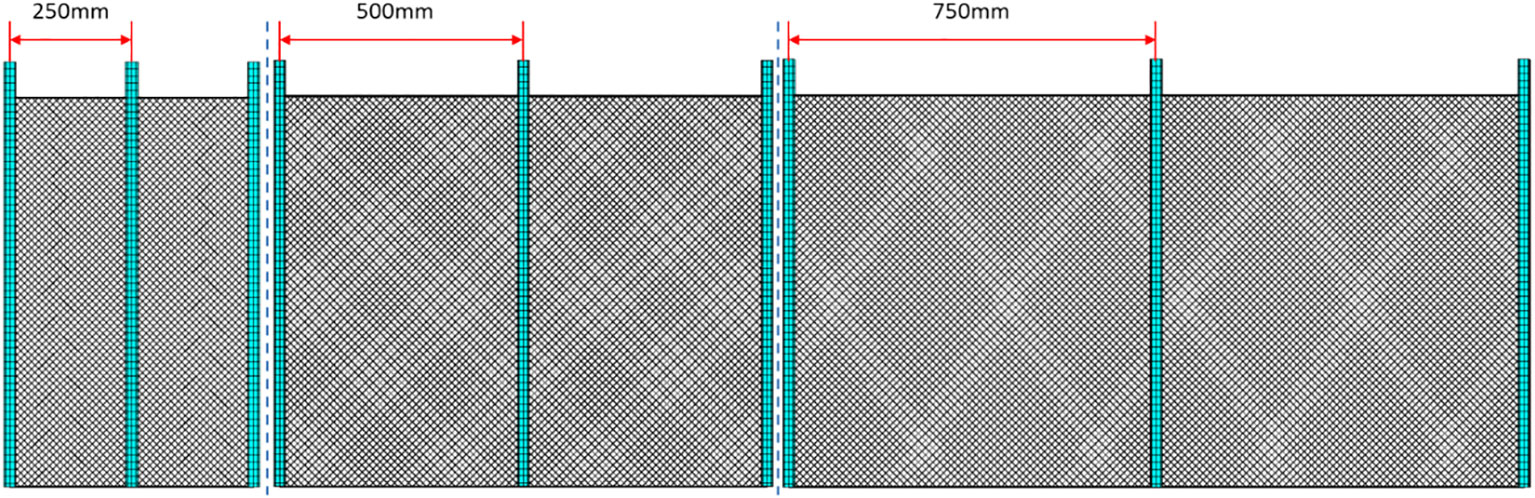
Figure 6 Three finite element models with different pile spacing.
The wave load shown in Table 3 is applied to the local model to calculate the wave forces on the local model under different wave heights and periods.
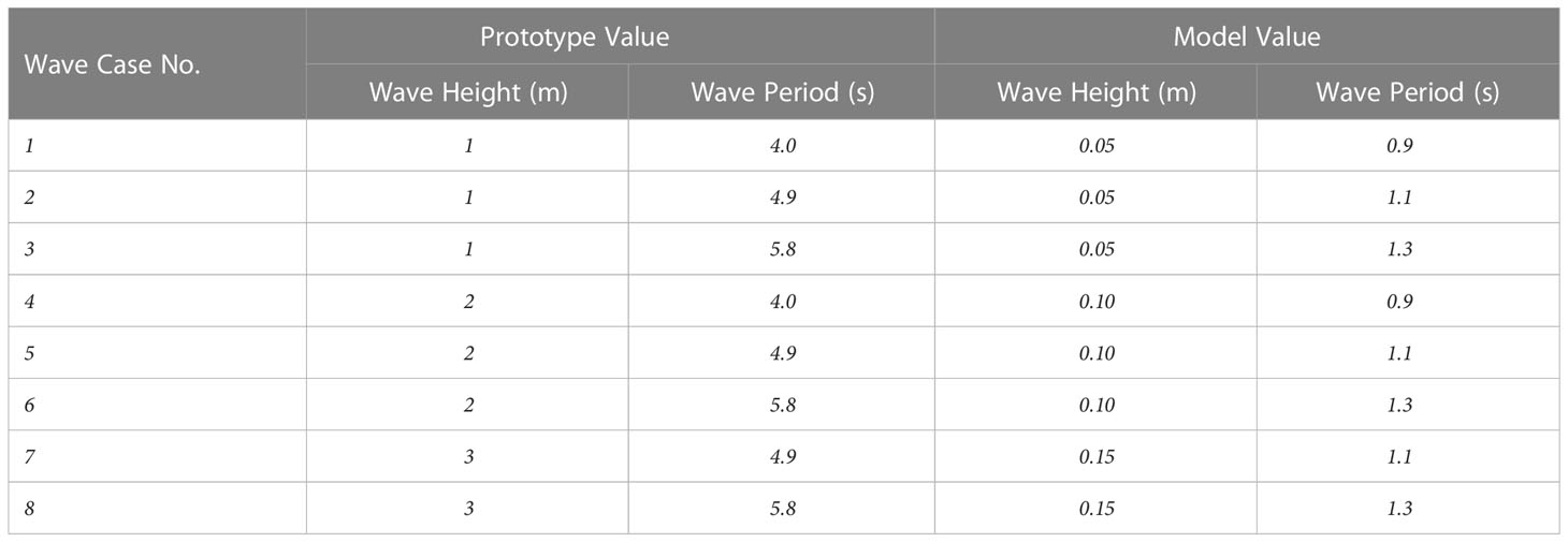
Table 3 Wave conditions for the numerical calculation and the local physical experiment.
According to the measurement method in the local model test, a full constraint is applied on the bottom of the local numerical model. The maximum force of the top point is extracted from the local model as the calculated wave force. The accuracy of the modeling method is verified by comparing the calculated wave force with the measured force of the pipe pile in the test as shown in Figure 7. From Figure 7, the average relative errors of the three spacing are 8.25%, 10.13% and 6.88% respectively. With the wave height of 50 mm, the local model receives less wave force, and the relative error between simulation and test is large, with the maximum relative error is 19%. The reason for the error between the experimental value and the simulated value may be that the mesh group method is adopted in the numerical simulation, and the influence of the grouped mesh on the waves is not considered. In addition, the details of the numerical model cannot be completely consistent with the model test, and there are small differences between the physical and numerical models (Liu et al., 2020). Therefore, the modelling accuracies and reasonability of the local model have been substantiated through the validations.
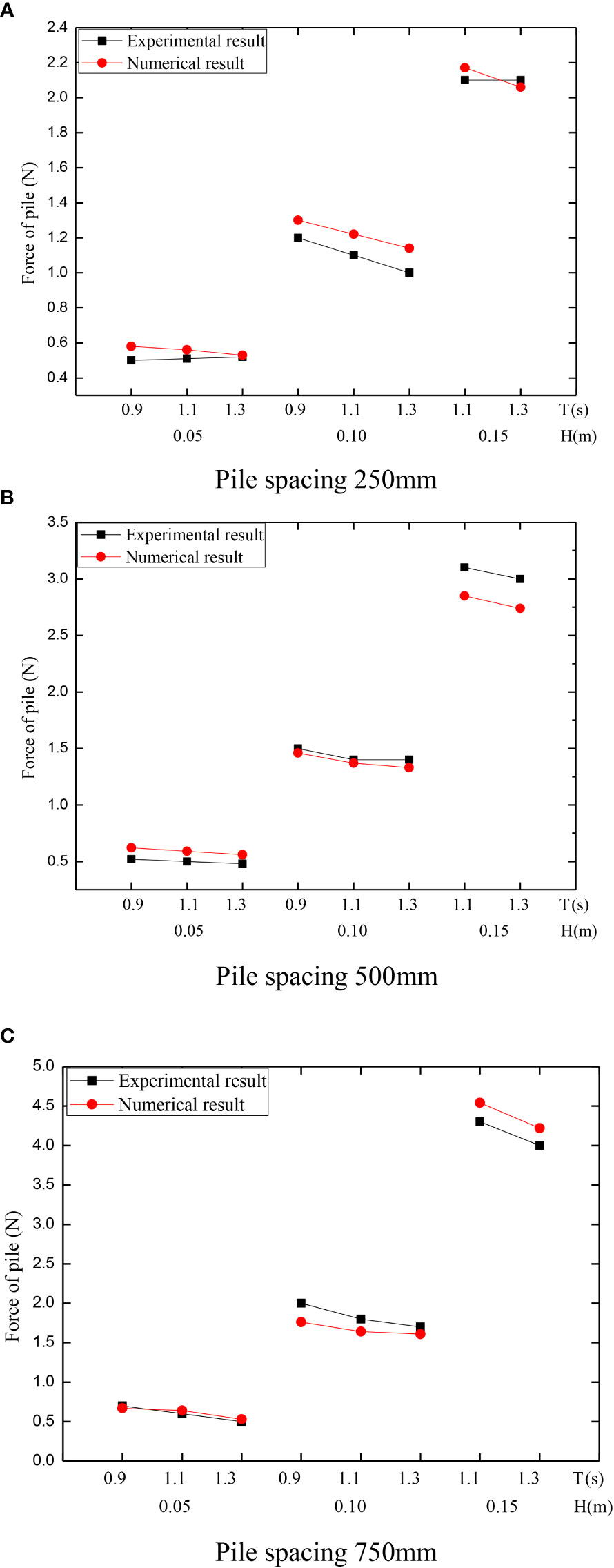
Figure 7 Comparison of the pile force between the calculated and experimental values. (A) Pile spacing 250mm. (B) Pile spacing 500mm. (C) Pile spacing 750mm.
4 Results
4.1 Wave forces and displacements of pipe piles
The wave induced forces and displacements of pipe piles in various wave cases are evaluated in this section, wherein the maximum forces of the pen perpendicular to flow are extracted in Figure 8 and Figure 9.
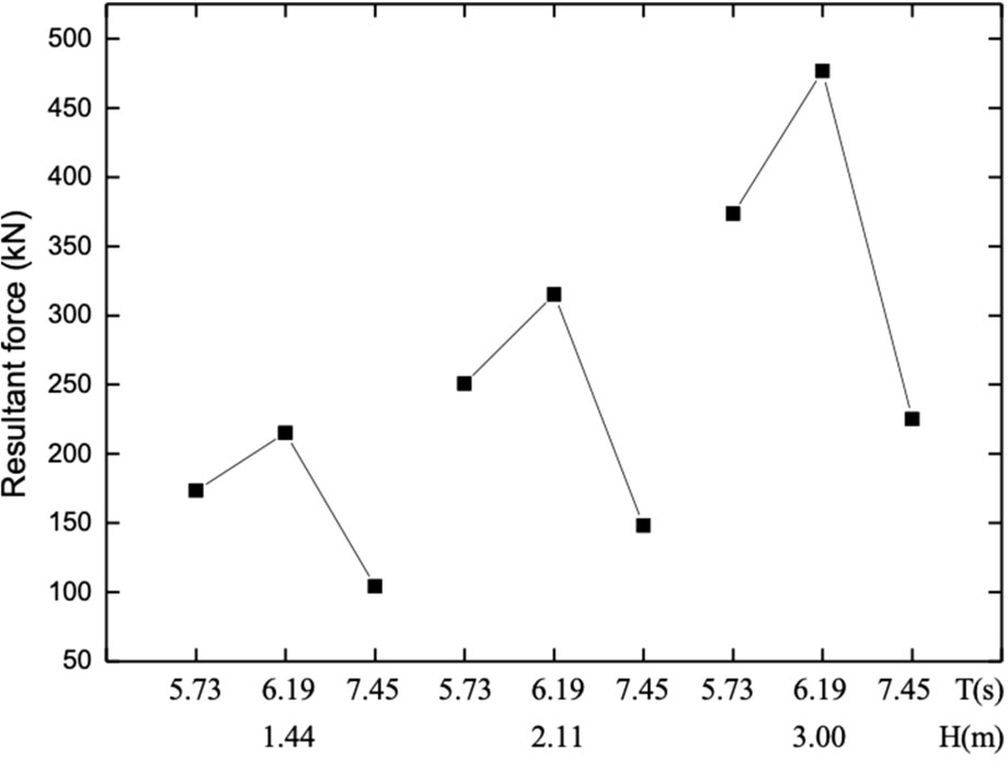
Figure 8 Maximum forces of pens.
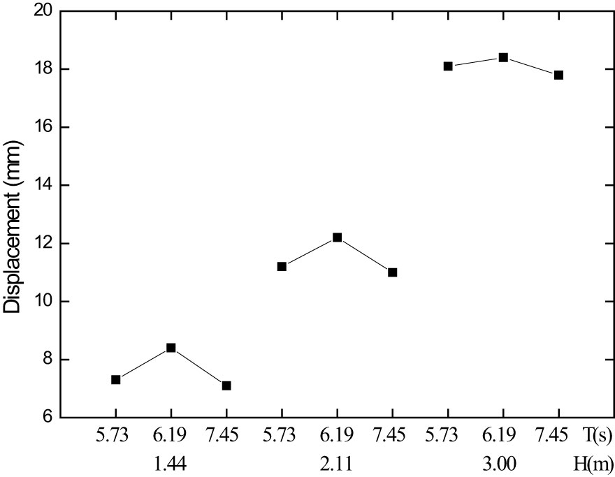
Figure 9 Displacements of pipe piles.
Since the hydrodynamic loads vary periodically with the evolvement of waves, the maxima of forces and displacements of piles within a period are analyzed in each case. Figure 8 presents the maximum force on piles with various wave periods and wave heights. It can be observed from Figure 8 that the maximum wave forces are closely proportional to wave heights. In addition, no obvious correlation exists amongst maximum forces and wave periods. The maximum force of the pen reaches 476.5 kN for the case with wave height 3.00 m and wave period 6.19 s. Figure 9 shows the maximum displacement of pipe piles with wave inputs. The variation of displacements with wave inputs has the similar tendency with that of maximum force. The maximum displacement of the pipe pile is about 18.4 mm for the case with wave height 3.00 m and wave period 6.19 s.
4.2 Bending moments of pipe piles and nets deformation
It is illustrated in Figure 10 that the variation patterns of bending moments of the pipe pile with elevations. For each case, the uniform trend can be observed that both positive and negative bending moments increase firstly and then decrease with the elevation. The maximum bending moment is within the range of 3 m below the seabed. Furthermore, the second largest bending moment is approximately located at the free surface. The above analysis results are in accordance with the numerical results of Gui et al. (2020). Meanwhile, the bending moment with the same elevation rises with the increasing of wave height. Given the consistent wave heights, there is no distinct correlation between bending moments and wave periods. For the case of which wave height is 3 m, the maximum bending moment of pile is 24609 N·m, which is still in the scope of the ultimate bending moment of pipe piles.

Figure 10 Variation of bending moments.
Figure 11 shows the variation of the deformations of nets in the streamwise direction with elevations. A general tendency can be detected that the displacement of nets increases first and then decreases with the elevation. The maximum displacement is within the range of 2 m beneath free surfaces. Moreover, the displacement of nets close to the free surface tends to zero. It is possibly attributed to the rope, of which the stiffness is considerably larger than the nets, assembled with the net panel at 500 mm above the sea. The maximum displacement is approximate 0.7 m corresponding to the case with wave height 1.44 m, while the maximum displacement reaches sharply to 1.6 m with wave height 3 m case, which is nevertheless doubled compared to the former one.
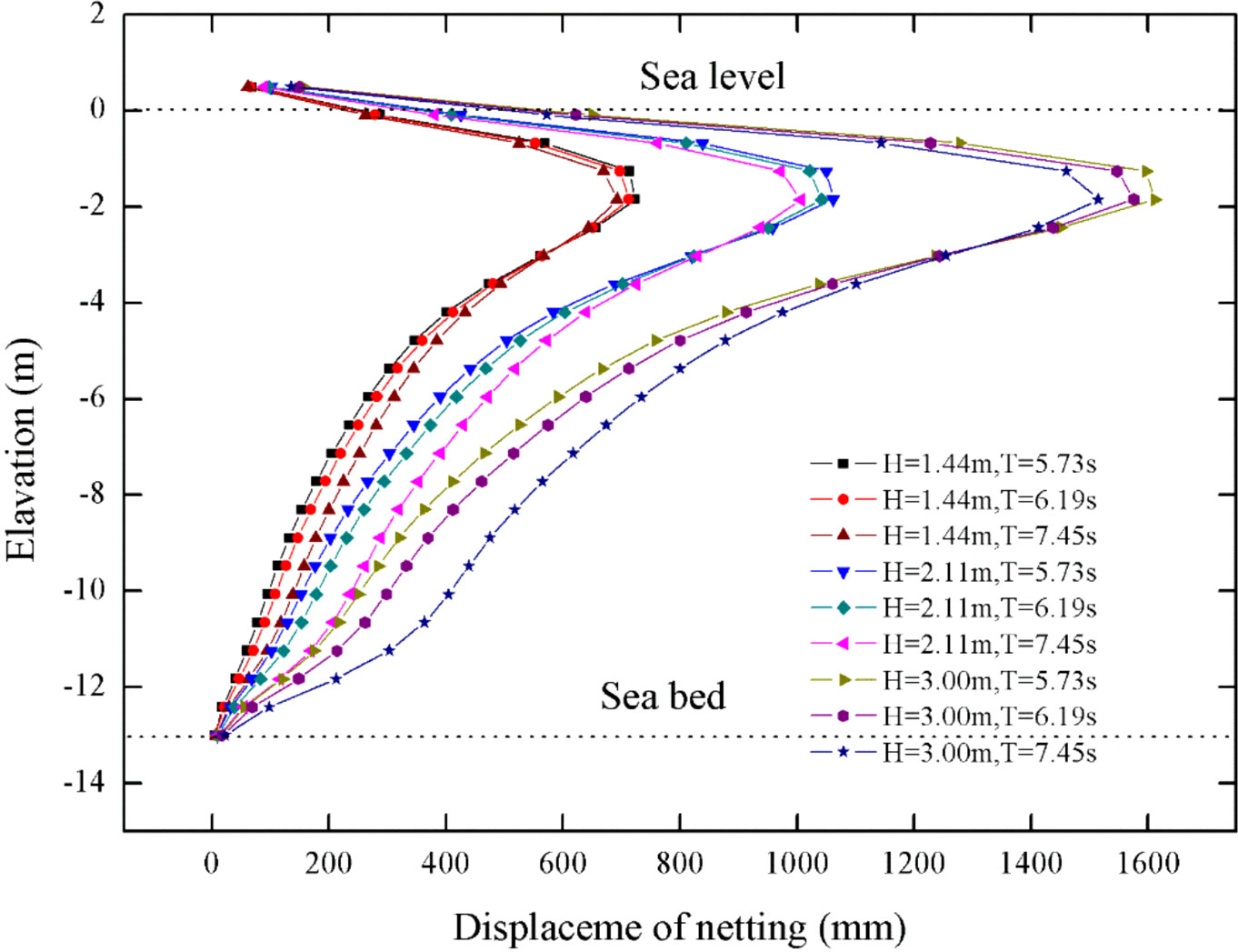
Figure 11 Variation of net deformations with varying waves inputs.
4.3 The first principal stresses of nets and beams
As the essential factor in the field of structural mechanics, the 1st principal stress has provided the maximum tensile stress induced in the part due to the hydrodynamic loadings, applied universally for the fragile materials. Thus, the rationalities of using this principle to evaluate stresses of nets and beams are justified. Figures 12 and 13 show the maximum stress of nets and beams in varying wave periods and heights, separately. It can be concluded from Figure 12 that the maximum stress of nets is significantly proportional to wave heights, while the maximum stresses are however presenting a downward trend with wave periods rising. Furthermore, it is noticeable in Figure 13 that the maximum stresses of beams exhibit the upward tendencies with the rise of wave heights, but is not dependent on the wave period. The maximum stress of nets reaches about 13.99 MPa with the case of wave height 3 m and wave period 5.73 s, while the maximum stress of beams is around 12.55 MPa with the case of the same wave height and wave period 6.19 s.

Figure 12 Maximum stress of nets.
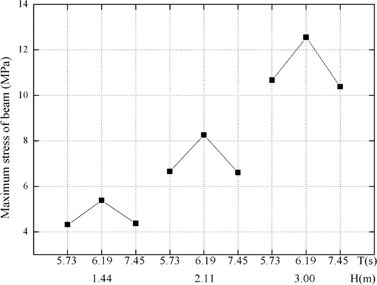
Figure 13 Maximum stress of beams.
5 Discussion
In comparison with typical net cages, the large-scale FPAP is an innovative type of offshore aquaculture facility. The evident advantages have been introduced at present such as the large cultural region, close-to-nature farming environment to prevent diseases and substantially adaptive for the sea areas with flat trend of China’s continental shelf. The relevance of designs and constructions of FPAP with hydrodynamic characteristics should be investigated further, thereby the effects of depths and spacings of pipe piles are discussed in this section.
5.1 Effect of embedded depth
The costs of finance and resources for FPAP in-situ constructions are much more significant contrast with the that of typical deep-water fish cages, especially for offshore pilings. The selections of embedded depth are of great significance to ensure the stability of the FPAP and reduce the construction cost. It can be observed from Figure 14 that as the embedded depth continues to increase, the maximum stress of nets declines throughout all wave scenarios. Additionally, when the embedded depth is 7.5 m, the maximum tension of the nets is about 1% higher than that of 9.0 m on average. It has the implication that the embedded depth shows few impacts on the stress of side nets. Meanwhile, it is apparent from Figure 15 that the maximum displacement of piles exhibits a downward trend with embedded depths rising. It can be calculated that the maximum reduction reaches 9.2% with the rise of embedded depths, for the case of which wave height is 2.11 m and wave period is 5.73 s. The simulated results are also consistent with Gui et al. (2020) qualitatively and quantificationally.
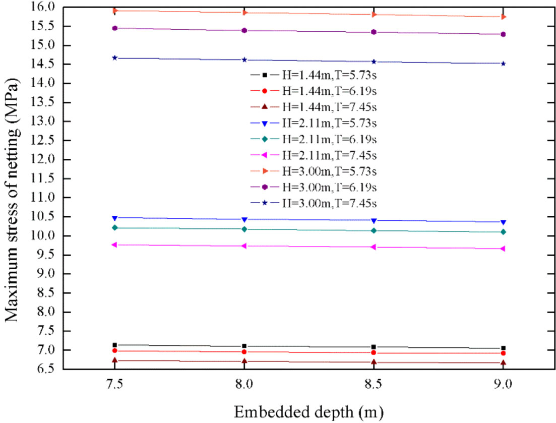
Figure 14 Maximum stress of nets.
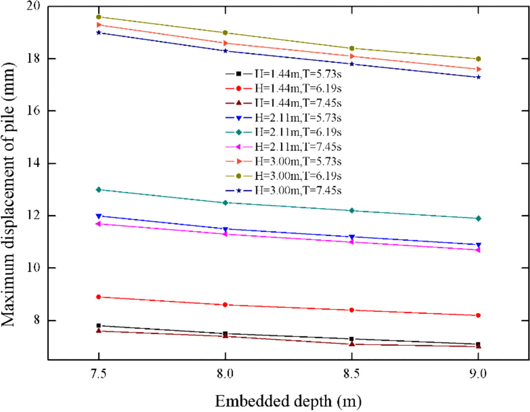
Figure 15 Maximum displacement of piles.
Figure 16 shows that the maximum stresses of beams marginally increase with the embedded depth. A possible explanation lies in the position of the beam, which is closer to the water surface with the increase of embedded depth. Provided the embedded depth ranges from 7.5 m ~ 9.0 m, the maximum stresses of the beam rise by 2.2% on average across all wave cases. In general, the depth of pile piling has little effect on pile displacements, stresses of net twines and beams. To ensure the stability of the pen structure, embedded depth should be decided according to the specific conditions of seabed geology, otherwise the costs and the challenges of piling operations would be considerable. For the consideration of providing a more general recommendations for FPAP in other regions, the effects of a wider range of embedded depths on hydrodynamics and structural mechanics deserve further investigations in the future study.

Figure 16 Maximum stress of beams.
5.2 Effect of pipe pile spacing
When the pile gap to diameter (L/D) is smaller than 4, the experimental results indicate wave transmission between piles can have a more significant influence, that is, the pile group effect (Xu, 2019). In addition to embedded depths, the selection of pipe pile spacing should also be considered on the basis of the safety of FPAPs and the cost of constructions. In order to study the influence of pipe pile spacing on the hydrodynamic properties of FPAPs, the distance between pipe piles is selected from 4.0 m to 6.2 m. The pile group effect is negligible to be ignored outside of this range. Figure 17 shows the maximum displacement of nets with elevations for three kinds of pile spacings. It can be noted that the deformations of nets tend to increase with the increase of pipe pile spacing, and the relative increment can reach 34%. Meanwhile, the maximum displacements of the nets across all cases can be simultaneously detected close to free surfaces, implying that the nets interacted with free surfaces should be reinforced to prevent the potential damages. Keeping the wave inputs and the embedded depth constant, it is pronounced from Figure 18 that the maximum displacements of piles get enhanced with enlarging the pile spacing. Given the shrinking of the number of pipe piles, the stiffness of the FPAP can be weakened and the induced distinct deformations of nets and beams would threaten the safety of the overall structure. The variation patterns of the stresses of nets and beams with pile-spacing are demonstrated in Figure 19 and Figure 20. It can be principally concluded that net stresses would decline while enlarging pile-spacing, and the varying trend of beam stresses is similar as that of the net stresses. The stresses of net twines and beams decrease by 2% and 4% on average while the pile spacings corresponding from 4.5 m to 5.5 m.
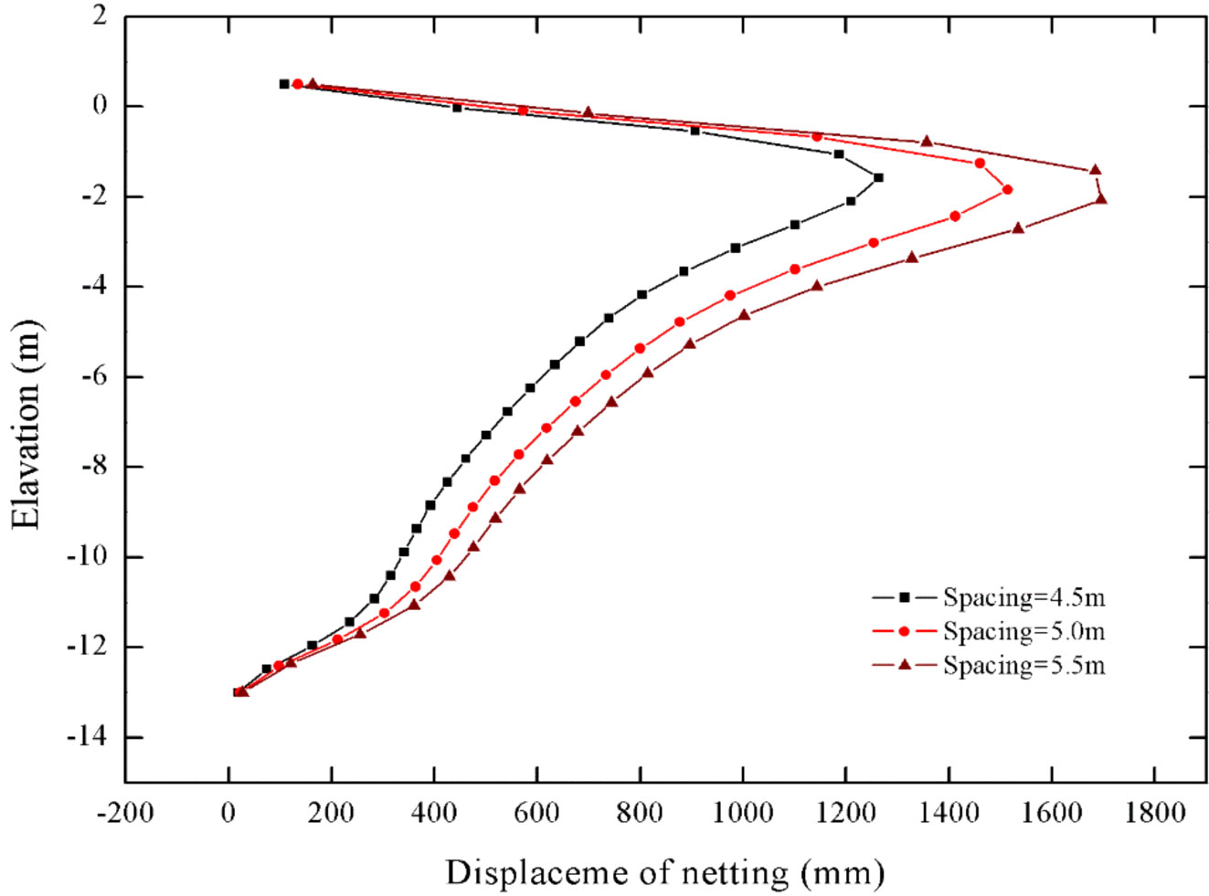
Figure 17 Displacement of nets with elevations.

Figure 18 Maximum displacement of pile with pile spacings.
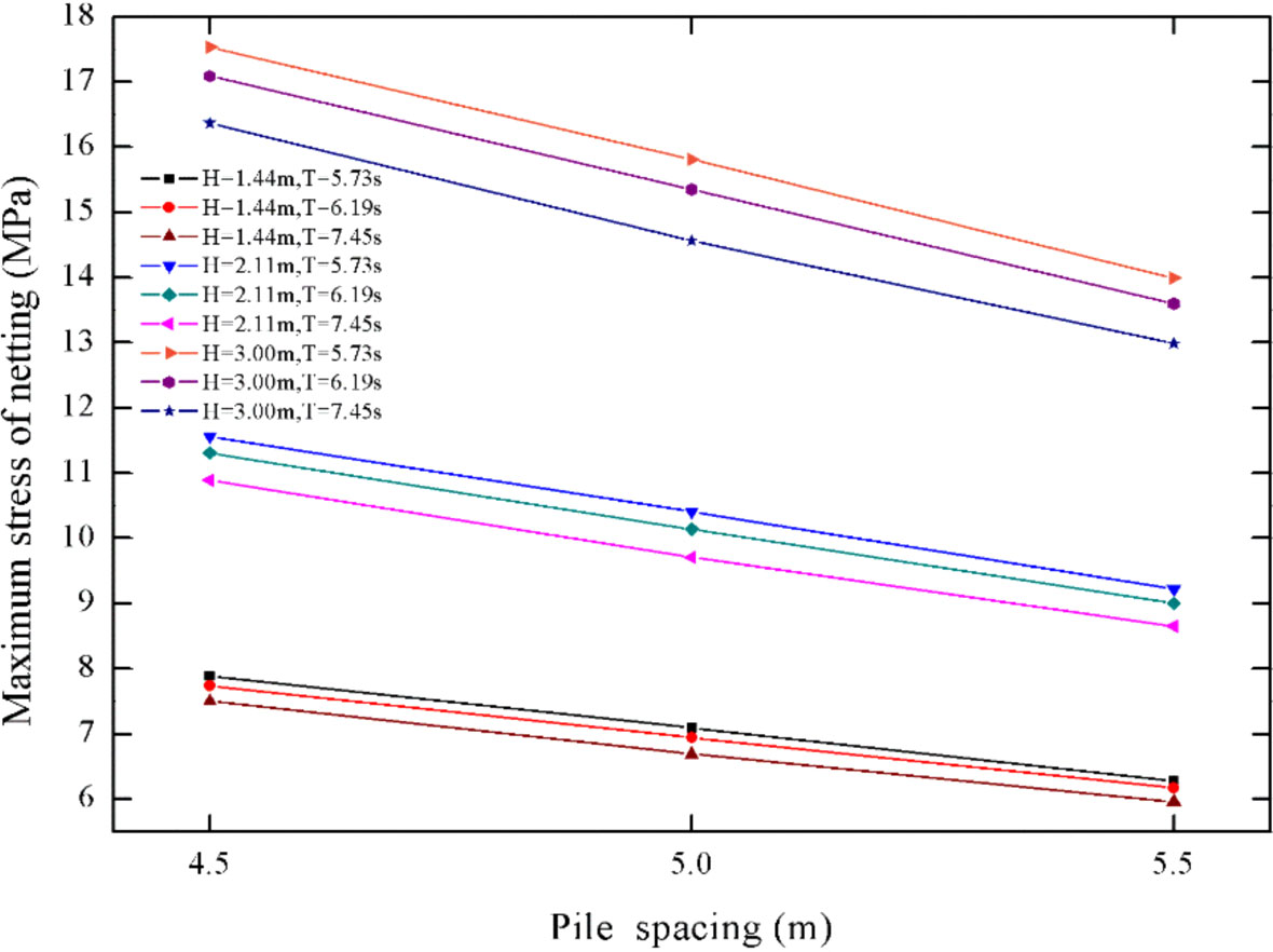
Figure 19 Maximum stress of nets with pile spacings.
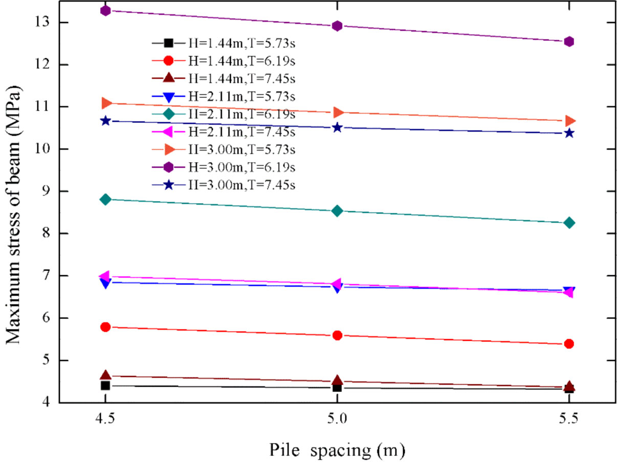
Figure 20 Maximum stress of beams with pile spacings.
5.3 Structural optimizations
In this part, the case with the dominated induced displacements (pipe pile spacing 6.25 m, embedded depth 7.50 m, wave height 3.00 m, wave period 6.19 s) are utilized, taking the most extreme scenario into consideration. The wave forces in three directions, joint forces of the I-beam at the top of the pen and the welding points of piles are provided for the strength check of the welding site. As the area outlined in Figure 21, the maximum force on the top beam is about 12.53 kN.
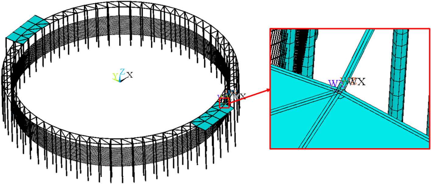
Figure 21 Position of maximum force point of pipe pile.
Diverse from the typical offshore structures with piles, the flexible side-net systems are equipped with FPAPs. As demonstrated in Figure 22, the wave loads on and deformation of the nets in the proximity of free surfaces are the largest. After the deployment, it should be noticed that the bio-fouling issues of nets are quite substantial for a long duration, resulting in the surging of hydrodynamic drags. As a result, the nets of the FPAP needs to be cleaned timely to prevent net-mesh blockage and the induced damages.
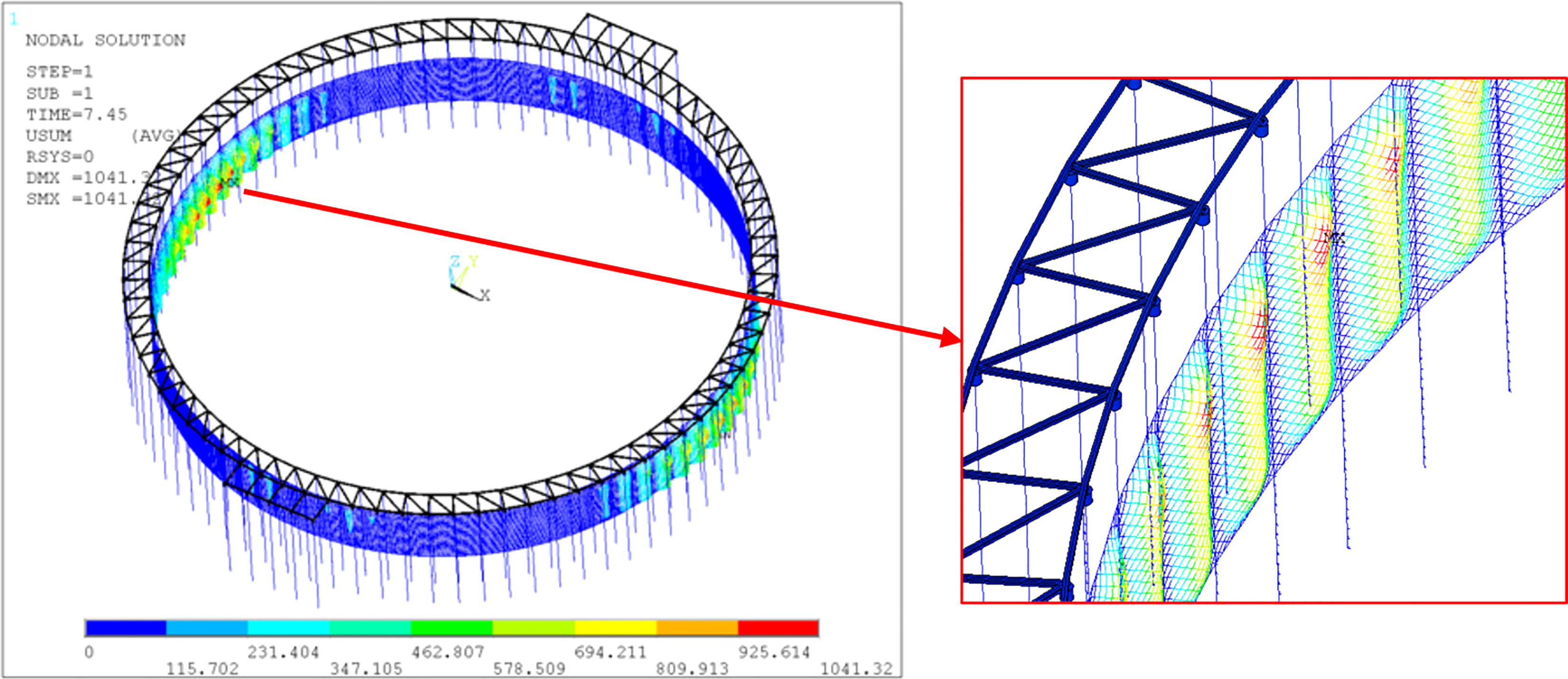
Figure 22 Position of maximum displacement of nets.
In the Figure 23, the stress is relatively concentrated at the welding position of the beam composed of the walking board. The maximum stress in regular waves is 79.33 MPa for the case of which wave height 3.00 m and wave period 5.74 s. Due to the concentration of stresses, there is the possibility that the cracking event at the welded region can occur, emphasizing the dominance of welding qualities during constructions. It is recommended that the reinforcement plate as shown in Figure 24 be added at the weld position where the weld is prone to be damaged. Following the optimizations in the Figure 25, after adding the reinforced plate, the stress decreases from 79.33 MPa to 44.45 MPa, which greatly reduces the stress level and the risk of cracking.

Figure 23 Stress results of beam of walking board.
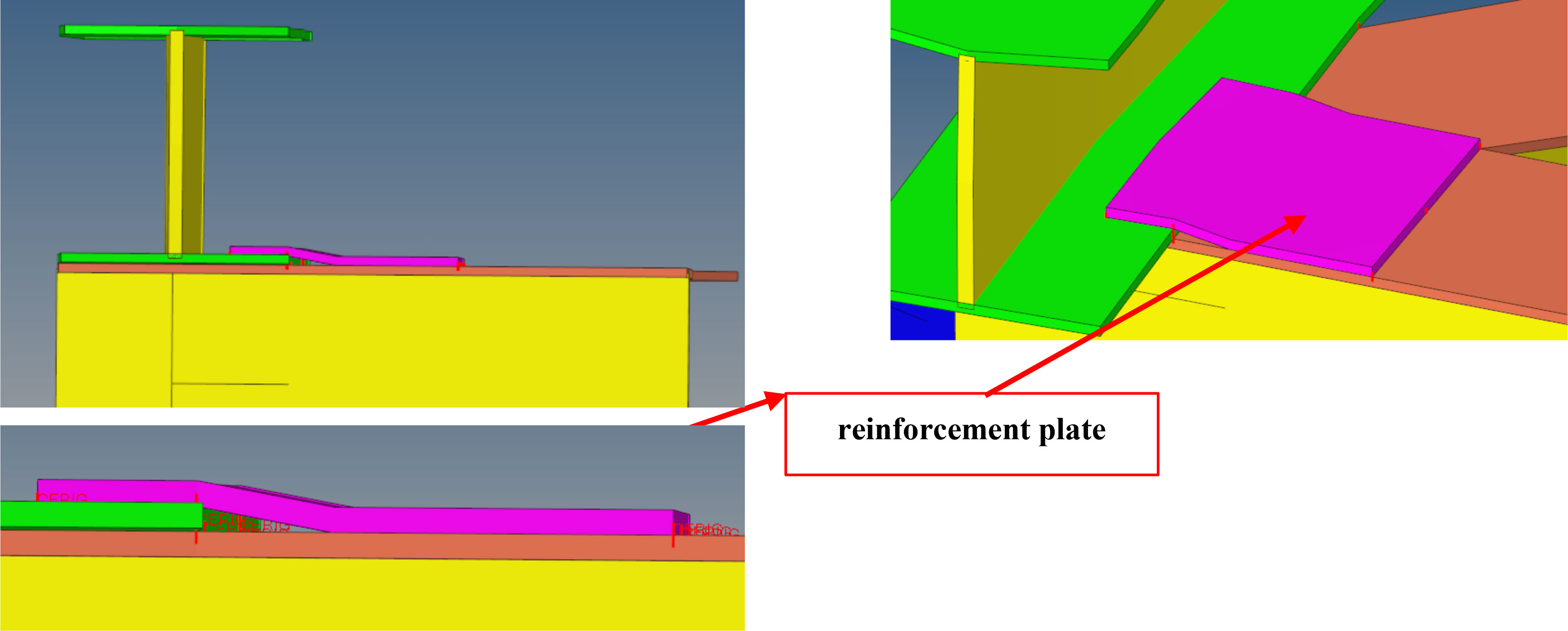
Figure 24 Suggestions on optimization of beam welding.

Figure 25 Stress before optimization and after optimization.
6 Conclusions
In this study, the hydrodynamic responses of a novel FPAP in regular waves are investigated using the finite element modelling. The accuracies of numerical methods have been verified against the physical measurements, with the relative error of wave loads is about 10%. Then hydrodynamic loads on and structural responses of the FPAP are analyzed and discussed. The structural optimizations regarding reducing the stresses to prevent cracking are conducted finally. The conclusions are summarized as follows:
(1) The maximum force of the pen and the maximum displacement of the pipe pile are closely proportional to the wave height. In addition, the change of wave period has little effect on the force and deformation. The maximum bending moment is within the range of 3 m below the seabed. When wave height is 3 m, the maximum bending moment of pile is 24609 N·m. The displacement of nets increases first and then decreases with the structure elevation, and the maximum displacement is within the range of 2 m below the sea level. The maximum stress of nets is about 13.99 MPa and the maximum stress of beam is about 12.55 MPa.
(2) As the embedded depth continues to increase, the maximum stress of nets decreases under nine wave conditions. Meanwhile, the maximum displacement of pile exhibits a downward trend with increasing embedded depth. The maximum stress of beam increases slowly with the increase of embedded depth. In general, the depth of pile driving has little effect on the deformation of pipe pile, the stress of nets and beam.
(3) The deformation of nets tends to increase with the increase of pipe pile spacing, and the maximum displacement of pile exhibits a rising trend with increasing pile spacing under the same wave condition and embedded depth. Meanwhile, nets stress and beam stress will exhibit a downward trend for the pen with increasing pile spacing.
(4) Some suggestions on the optimization of the pen structure are given. The nets of the FPAP needs to be cleaned on time to prevent damage. It is recommended to add a reinforcement plate at the weld position where the weld is prone to cracking, which will greatly reduce the stress level and the risk of cracking.
Data availability statement
The original contributions presented in the study are included in the article/supplementary material. Further inquiries can be directed to the corresponding author.
Author contributions
YC: Data curation, formal analysis, funding acquisition, writing the original draft, review. GW: investigation, methodology, review. C-TG: investigation, funding acquisition, supervision. All authors contributed to the article and approved the submitted version.
Funding
This work was financially supported by the National Key R&D Program of China (No. 2019YFD0900902); National Natural Science Foundation of China (No. 31772898); Maritime S&T Fund of Shandong Province for Pilot National Laboratory for Marine Science and Technology (Qingdao) (No. 2018SDKJ0303-4); China Agriculture Research System of MOF and MARA (No. CARS-47-22); Central Public-interest Scientific Institution Basal Research Fund, CAFS (No. 2020TD51).
Conflict of interest
The authors declare that the research was conducted in the absence of any commercial or financial relationships that could be construed as a potential conflict of interest.
Publisher’s note
All claims expressed in this article are solely those of the authors and do not necessarily represent those of their affiliated organizations, or those of the publisher, the editors and the reviewers. Any product that may be evaluated in this article, or claim that may be made by its manufacturer, is not guaranteed or endorsed by the publisher.
References
ANSYS Inc (2009). ANSYS user’s manual (Southpointe, 275 Technology Drive, Canonsburg, PA: ANSYS Inc.).
Bi C.-W., Zhao Y.-P., Dong G.-H., Xu T.-J., Gui F.-K. (2013). Experimental investigation of the reduction in flow velocity downstream from a fishing net. Aquacult. Eng. 57, 71–81. doi: 10.1016/j.aquaeng.2013.08.002
Bi C. W., Zhao Y. P., Dong G. H., Xu T. J., Gui F. K. (2014). Numerical simulation of the interaction between flow and flexible nets. J. Fluids Struct. 45, 180–201. doi: 10.1016/j.jfluidstructs.2013.11.015
Chen T.-H., Pan Y., Feng D.-J., Meng A., Gui F.-K. (2018). Effect on hydrodynamics of unit net of a column-type net enclosure aquaculture engineering in current by fixations. J. Fish. China. 42, 452–460.
Chu Y. I., Wang C. M., Park J. C., Lader P. F. (2020). Review of cage and containment tank designs for offshore fish farming. Aquaculture 519, 73492. doi: 10.1016/j.aquaculture.2020.734928
Cifuentes C., Kim M.-H. (2017). Hydrodynamic response of a cage system under waves and currents using a morison-force model. Ocean Eng. 141, 283–294. doi: 10.1016/j.oceaneng.2017.06.055
Cui Y., Guan C.-T., Wan R., Huang B., Li J. (2013). Numerical simulation of a flatfish cage system in waves and currents. Aquacult. Eng. 56, 26–33. doi: 10.1016/j.aquaeng.2013.04.001
Cui Y., Guan C.-T., Wan R., Huang B., Li J. (2014). Dynamic analysis of hydrodynamic behavior of a flatfish cage system under wave conditions. China Ocean Eng. 28, 215–226. doi: 10.1007/s13344-014-0017-4
Gharechae A., Ketabdari M. J. (2020). Semi-analytical study on regular sea wave interaction with circular elastic floaters of aquaculture fish cages. Aquacult. Eng. 91, 102125. doi: 10.1016/j.aquaeng.2020.102125
Gui F.-K., Zhang B.-B., Qu X.-Y., Wang P., Shao Z.-Y., Feng D.-J. (2020). Force analysis of piles in net enclosure aquaculture engineering subjected to waves and current. Trans. Chin. Soc Agric. Eng. 36, 31–38.
He Z., Faltinsen O. M., Fredheim A., Kristiansen T. (2018). The influence of fish on the mooring loads of a floating net cage. J. Fluids Struct. 76, 384–395. doi: 10.1016/j.jfluidstructs.2017.10.016
Huang X.-H., Guo G.-X., Tao Q.-Y., Hu Y., Liu H.-Y., Wang S.-M., et al. (2018). Dynamic deformation of the floating collar of a net cage under the combined effect of waves and current. Aquacult. Eng. 83, 47–56. doi: 10.1016/j.aquaeng.2018.08.002
Huang L., Li Y., Ni Y., Cheng H., Wang X., Wang G., et al. (2019). “Study on the influence of mesh grouping on numerical simulation results of fish cages,” in Proceedings of the ASME 2019 38th International Conference on Ocean, Offshore and Arctic Engineering. volume 9: Rodney Eatock Taylor Honoring Symposium on Marine and Offshore Hydrodynamics; Takeshi Kinoshita Honoring Symposium on Offshore Technology. Glasgow, UK. V009T13A040. doi: 10.1115/OMAE2019-95706
Liu H.-F., Bi C.-W., Zhao Y.-P. (2020). Experimental and numerical study of the hydrodynamic characteristics of a semisubmersible aquaculture facility in waves. Ocean Eng. 214, 107714. doi: 10.1016/j.oceaneng.2020.107714
Mohapatra S. C., Bernardo T. A., Soares G. (2021). Dynamic wave induced loads on a moored flexible cylindrical net cage with analytical and numerical model simulations. Appl. Ocean Res. 110, 102591. doi: 10.1016/j.apor.2021.102591
Tsukrov I., Eroshkin O., Fredriksson D., Swift M.R., Celikkol B. (2003). Finite element modeling of net panels using a consistent net element. Ocean Eng. 30, 251–270. doi: 10.1016/S0029-8018(02)00021-5
Wan R., He X., Wang X.-X., Liu L.-L. (2007). A method of mesh group for fish cage anti-current characteristics by means of finite element analysis. J. Ocean Univ. China. 37, 885–888.
Xia T., Yang P., Li C., Hu K. (2019). Numerical research on residual ultimate strength of ship hull plates under uniaxial cyclic loads. Ocean Eng. 172, 385–395. doi: 10.1016/j.oceaneng.2018.12.017
Xu P.-X. (2019). Dynamic response analysis and reliability study of deep-water jacket platform structure (Chengdu, China: Southwest Petroleum University).
Yang H., Bi C.-W., Zhao Y.-P., Cui Y. (2020). Numerical study on hydrodynamic responses of floating rope enclosure in waves and currents. J. Mar. Sci. Eng. 8, 82. doi: 10.3390/jmse8020082
Zhao Y.-P., Bi C.-W., Chen C.-P., Li Y.-C., Dong G.-H. (2015). Experimental study on flow velocity and mooring loads for multiple net cages in steady current. Aquacult. Eng. 67, 24–31. doi: 10.1016/j.aquaeng.2015.05.005
Zhao Y.-P., Chen Q.-P., Bi C.-W. (2022). Numerical investigation of nonlinear wave loads on a trestle-netting enclosure aquaculture facility. Ocean Eng. 257, 111610. doi: 10.1016/j.oceaneng.2022.111610
Keywords: fully-enclosed pile-net aquaculture pen (FPAP), offshore aquaculture, hydrodynamics, embedded depth, pile spacing
Citation: Cui Y, Wang G and Guan C-t (2023) Numerical and experimental investigations of hydrodynamics of a fully-enclosed pile-net aquaculture pen in regular waves. Front. Mar. Sci. 10:1175852. doi: 10.3389/fmars.2023.1175852
Received: 28 February 2023; Accepted: 14 April 2023;
Published: 15 May 2023.
Edited by:
Yang Jin, Johns Hopkins Medicine, United StatesReviewed by:
Hung-Jie Tang, National Cheng Kung University, TaiwanChunwei Bi, Ocean University of China, China
Copyright © 2023 Cui, Wang and Guan. This is an open-access article distributed under the terms of the Creative Commons Attribution License (CC BY). The use, distribution or reproduction in other forums is permitted, provided the original author(s) and the copyright owner(s) are credited and that the original publication in this journal is cited, in accordance with accepted academic practice. No use, distribution or reproduction is permitted which does not comply with these terms.
*Correspondence: Chang-tao Guan, guanct@ysfri.ac.cn