Underwater terrain positioning method based on Markov random field for unmanned underwater vehicles
 Pengyun Chen
 Ying Liu2*
  Teng Ma
- 1School of Aerospace Engineering, North University of China, Taiyuan, China
- 2College of Oriental Languages, Harbin Normal University, Harbin, China
- 3China Ship Development and Design Center, Wuhan, China
- 4Science and Technology on Underwater Vehicle Laboratory, Harbin Engineering University, Harbin, China
Underwater terrain-matching navigation technologies have become a popular topic for the high-precision positioning and navigation of autonomous underwater vehicles. This paper proposes an underwater terrain-matching positioning method based on a Markov random field model, which is based on real-time terrain data obtained using a multi-beam echo sounder. It focuses on the strong correlation between adjacent terrain data, which can improve terrain adaptability and matching accuracy. Playback simulation tests were conducted based on actual sea trial data, and the results showed that the proposed method has good positioning performance, which can correct the cumulative errors of inertial navigation systems. The results demonstrated the usability of the proposed method for positioning correction in underwater engineering applications.
1 Introduction
Underwater terrain matching navigation (UTMN) technology has become a popular research topic in developing an error correction method for inertial navigation systems (INSs) for the underwater sailing of unmanned underwater vehicles (UUVs) (Huang et al., 2019; Zhang et al., 2020a).
Several terrain-matching methods are available. Terrain contour matching (TERCOM) and Sandia inertial terrain-aided navigation (SITAN) have been successfully used for aircraft navigation (Feng, 2004). Unlike terrain matching methods applied in aircrafts, UTMN has long been impeded by high-precision underwater terrain data. With the wide use of underwater multi-beam terrain measurement technology, it has become possible to create underwater digital terrain maps (DTMs) with high accuracy, enabling an in-depth study of UTMN (Hagen et al., 2012; Li et al., 2018).
In contrast to single-beam (Zhang et al., 2020b) and multi-line (Salavasidis et al., 2019) measurement methods, hundreds or even thousands of sounding data can be obtained simultaneously using a multi-beam echo sounder (MBES), where the measured terrain is the surface terrain, which can provide abundant sounding data as a solid foundation for UTMN (Jalving et al., 2004). Generally, UTMN methods based on MBES can be divided into two categories: continuous terrain filtering methods (CTFMs) and underwater terrain positioning methods (UTPMs). CTFMs include the Kalman filter (Zhou and Zheng, 2012), particle filter (Zhao et al., 2015; Teixeira et al., 2017), and point-mass filter (Bergman and Ljung, 1997), which were developed using SITAN. Thus, CTFMs have been widely researched to achieve good matching performance and continuous navigation and positioning correction. However, continuous navigation and positioning correction are dependent on the continuous measurement of the terrain, and the measurement sensor must operate continuously, which consumes considerable amount of power. Owing to the poor energy reserves of UUVs, CTFMs based on MBES are not suitable for engineering applications unless the battery field has a major technological breakthrough (Ma et al., 2020). Thus, CTFMs typically use low-power sensors, such as the Doppler velocity log (DVL) and acoustic altimeter, for water depth measurements (Salavasidis et al., 2021; Jiang et al., 2022). Compared with CTFMs, UTPMs were developed using TERCOM, which only requires multiple terrain-measured profiles (ping), which is relatively more advantageous. Traditional UTPM algorithms are based on terrain correlation estimations such as least-squares (Chen et al., 2015a), maximum likelihood (Chen et al., 2012; Peng et al., 2016), and Bayesian estimation (Chen et al., 2019a). Theoretically, the terrain correlation estimations are affected by “error averaging,” which can reduce the positioning accuracy in terrain flat areas. Existing methods assume that depth data are independent of each other, and the correlation of adjacent terrain data is not considered. Thus, terrain features are not fully utilized in existing methods.
The Markov random field (MRF) is an effective mathematical model for describing the grayscale dependence between image pixels and has been successfully applied in image matching (Shekhovtsov et al., 2008). The gridded DTM has properties similar to those of a grayscale image (Ma, 2019), and neighboring terrain data also have dependency relationships. Thus, the MRF model can also be used to describe terrain features. Considering the strong correlation between terrain data, this paper proposes a UTPM based on the MRF model. Simulation results show that the proposed method has excellent positioning accuracy and real-time performance, which are suitable for UUV underwater navigation.
2 Terrain positioning model
The UTPM, which differs from the traditional terrain height matching model, is presented as a terrain feature matching model in this paper. Therefore, the relationship between terrain data is considered. After filtering and gridding (Chen et al., 2015b; Chen et al., 2021), a terrain data matrix is obtained based on real-time multi-beam data, which have the same gridding space as the priori DTM (Arashloo and Kittler, 2011). The structure of the MRF between the real-time terrain and the local priori DTM is shown in Figure 1.
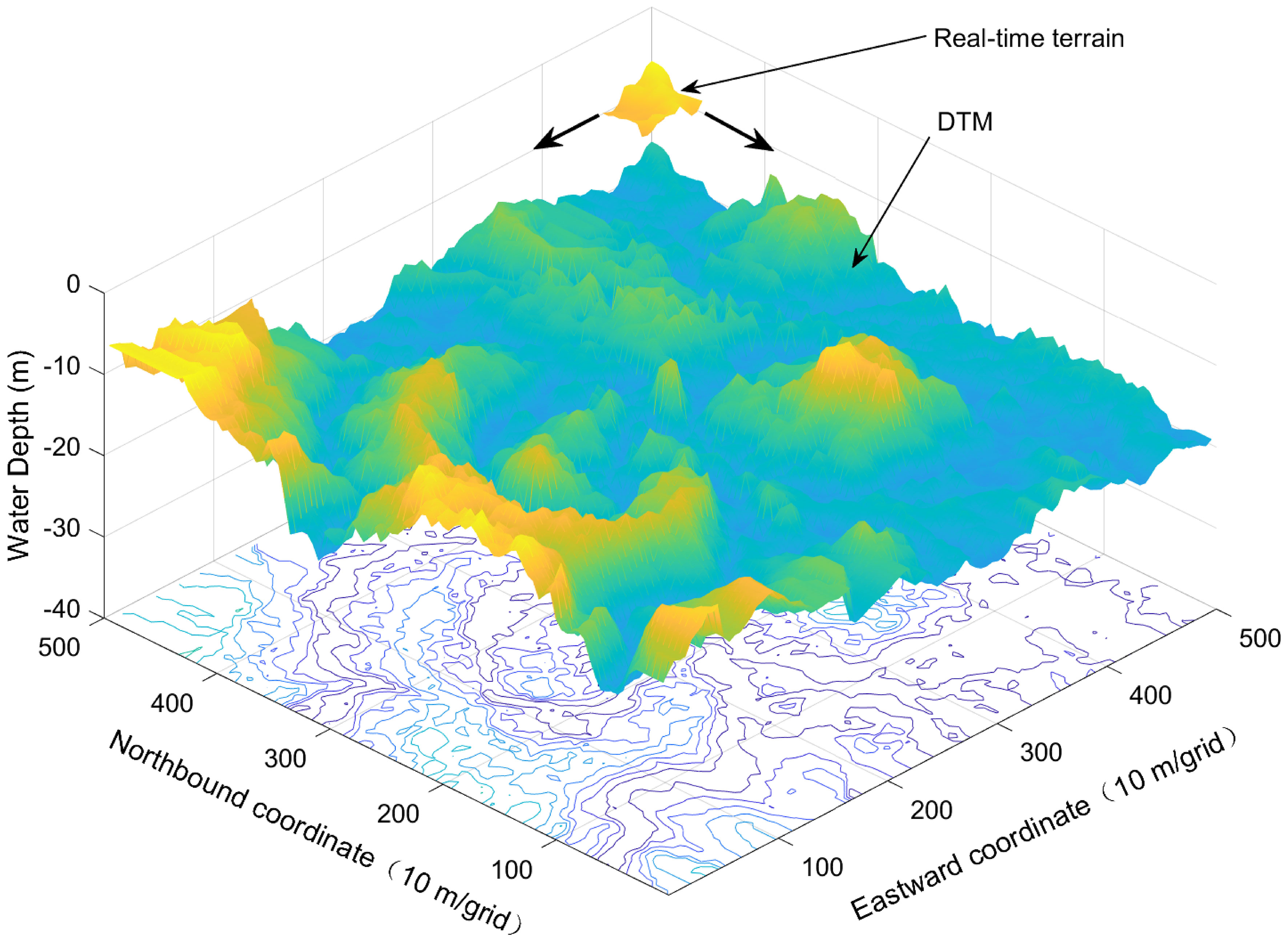
Figure 1 Schematic of UTMN.
In Figure 2, ID(x,y) and IR(x’,y’) are the depth data distributions of the local priori DTM and real-time terrain, respectively, and (x,y) and (x’,y’) are the coordinates of the terrain data in the local priori DTM and real-time terrain, respectively (Matthies and Okutomi, 1990; Xu and Chen, 2005),. From Figure 2, the underwater terrain-positioning model can be expressed using Eq. (1):

Figure 2 Structure of MRF.
where dx(x, y) and dy(x, y) are the position deviations of the real-time terrain, and e(x,y) is the measurement error. As shown in Eq. (1), the basic concept of MRF-based UTPM is to calculate the values of dx(x, y) and dy(x, y). To establish an MRF-based underwater terrain positioning model, the following assumptions are introduced in this study:
Assumption 1: The INS cumulative error obtained within a short time can be ignored, which is significantly more accurate than the multi-beam data error. Therefore, we assume that there is no relative position error in the terrain measurement during UTPM.
Assumption 2: Because of the continuity of the underwater terrain, there are strong correlations between adjacent terrain data. Thus, the terrain data have a probability dependency, which can be expressed by the MRF model.
Assumption 3: After grid processing, the locations of the terrain data are fixed in the real-time data and local priori DTM]; dx and dy are independent constants.
Assumption 4: The measurement error of MBES is not Gaussian, however, the noise mean is much smaller than the water depth, Thus, the measurement error can be can be approximately considered as Gaussian white noise.
3 MRF-based UTPM algorithm
3.1 Gibbs distribution of terrain data
Based on the above assumptions and the maximum a posteriori estimation principle, when the distributions of the local priori DTM and real-time terrain are known, the MRF-based UTPM problem can be described as determining the deviation (dx and dy) of the real-time terrain data from the local priori DTM, which maximizes the posterior probability distribution P(IR|ID) according to the Bayesian function:
As shown in Eq. (2), P(IR|ID) adheres to the MRF distribution, and the estimated values of dx and dy are related to the probability distributions of the measurement error P(e) and the real-time terrain P(IR). Thus, the aim of MRF-based UTPM is to determine P(e) and P(IR). According to the Harmmersley–Clifford theorem (Chen et al., 2019b) and Assumption 2, P(IR) can be expressed by the Gibbs function:
where Z is a normalized constant, and T is a temperature constant. U(IR) is an energy function related to IR. Based on the Gibbs distribution model proposed by Geman (Geman and Geman, 1984), U(IR) can be defined using Eq. (4).
where W is a matching window, and m and n are used to describe the four neighborhoods of the Gibbs distribution.
3.2 Position deviation estimation
Let WRand WD be matching windows of the same size, selected in the real-time terrain and local a priori DTM. From Eq. (1) and Assumption 3,
Using the Taylor expansion IR[x+dx,y+dy] at (x+dx,y+dy), Eq. (5) can be expressed as
Assuming dy=0, and considering the positional deviation in the x direction, let be based on Assumption 4 and Eq. (6) can be written as a function of dx.
and
Let , ; based on Eqs. (2), (3), (4) and (8), the following equation is obtained:
In Eq. (9), Kx is independent of dx. Therefore, the aim of the MRF-based UTPM is to determine a dx value that minimizes E(dx)+U(IR). The estimated value of dx is given by Eq. (10).
Where
Based on the same analysis, the value of dy is given by Eq. (12).
Therefore, the matching position results (x’,y’) are obtained as expressed in Eq. (14).
3.3 Matching process
The matching process is conducted as follows:
1. Inputting the real-time sounding data and the local priori DTM;
2. Filtering and gridding the real-time sounding data; let the real-time terrain have the same grid spacing as the local priori DTM;
3. Calculating the Gibbs distribution using Eq. (4);
4. Using Eq. (7), calculating ex(x,y) and ey(x,y);
5. Using Eqs. (10) and (12), calculating and ;
6. Using Eq. (14), calculating the matching position (x’,y’);
7. Outputting the calculation results to navigation.
The flowchart of the proposed method is shown in Figure 3.
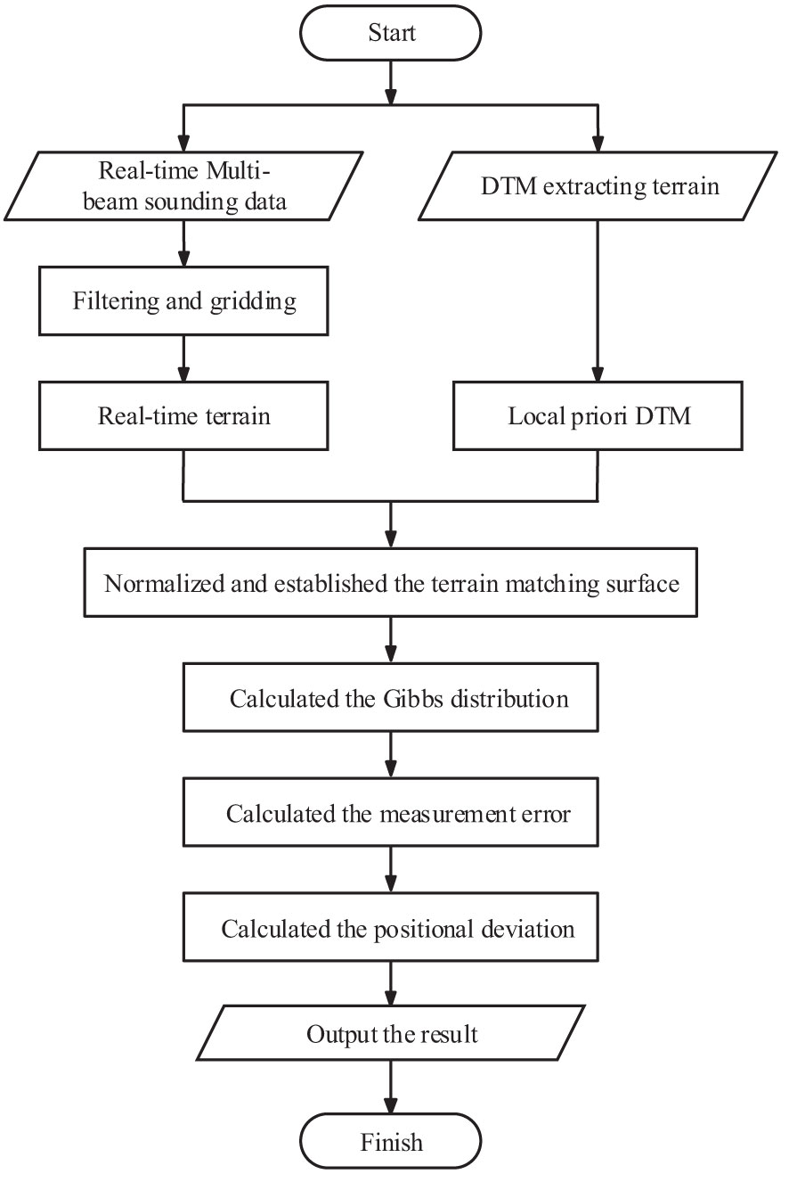
Figure 3 Algorithm flowchart.
In the proposed UTPM algorithm, terrain-matching positioning considers only the navigation deviation of the INS in the east and north directions, and the angle and sky deviations can be ignored. However, depth offset cannot be ignored. The reasons are as follows (Nygren, 2005; Chen et al., 2019b; Salavasidis et al., 2019):
1. The UTPM is an MBES, and the matching results are minimally affected by other sensor errors. The impact of systematic errors in attitude (including heading, pitch, and roll) on measurement data is virtually negligible in most terrain-aided navigation methods if adequate motion sensors are available.
2. Although the INS error is a combined effect of multiple error sources in the velocity and heading measurements, the drift in attitude is much smaller than the drift in the position estimates.
3. In addition, both the pressure sensor and altimeter provide accurate measurements to estimate the depth with an error of less than 0.01% of the operation depth.
4. Because of unknown tides and random waves, the depth offset cannot be disregarded. Therefore, it is necessary to eliminate the reference depth deviation while normalizing and establishing a terrain-matching surface.
4 Simulation and analysis
4.1 Simulation system
Simulation tests were conducted using an underwater semi-physical simulation system. The system center was a PC104 embedded computer. The structure of the simulation system is shown in Figure 4.
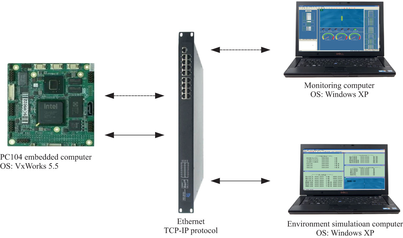
Figure 4 Structure of the semi-physical simulation system.
The simulation system comprised three parts: a monitoring computer, environment simulation computer, and PC104 embedded computer.
The monitoring computer was an actual AUV monitoring computer responsible for issuing task-level parameters and start-up instructions. Additionally, the “AUV” status information could be displayed. The environment simulation computer simulated the AUV movement in the marine environment and the sensors carried by the AUV. The PC104 embedded computer ran the AUV control system and had the same parameters as the master computer of the AUV. The difference was that the sensor information was the data packet sent by the environment simulation computer, and the actuator information was also sent to the environment simulation computer via Ethernet. The primary parameters of the PC104 computer are listed in Table 1.
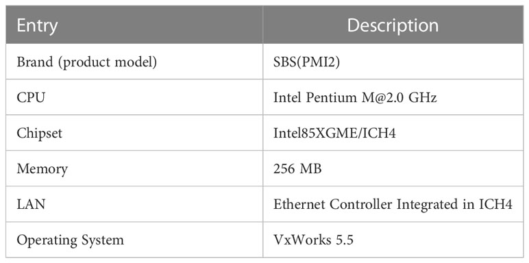
Table 1 Specifications of the PC104 computer.
Based on the simulation system, the simulation test was divided into two parts:
Test 1: Algorithm validation based on different terrain feature conditions to verify feasibility of the proposed algorithm.
Test 2: Playback simulation test using complete MBES survey line data to verify the applicability of the proposed algorithm in a real marine environment.
4.2 Simulation data source
During the simulations, the DTM data source was measured using a GeoSwath Plus (GS+) during a sea trial (Figure 5). GS+ is a typical MBES based on the principle of phase interference (GeoAcoustics Limited, 2007), produced by Kongsberg GeoAcoustics Ltd., Great Yarmouth, UK. The hardware composition of GS+ is shown in Figure 5, and its main parameters are listed in Table 2.
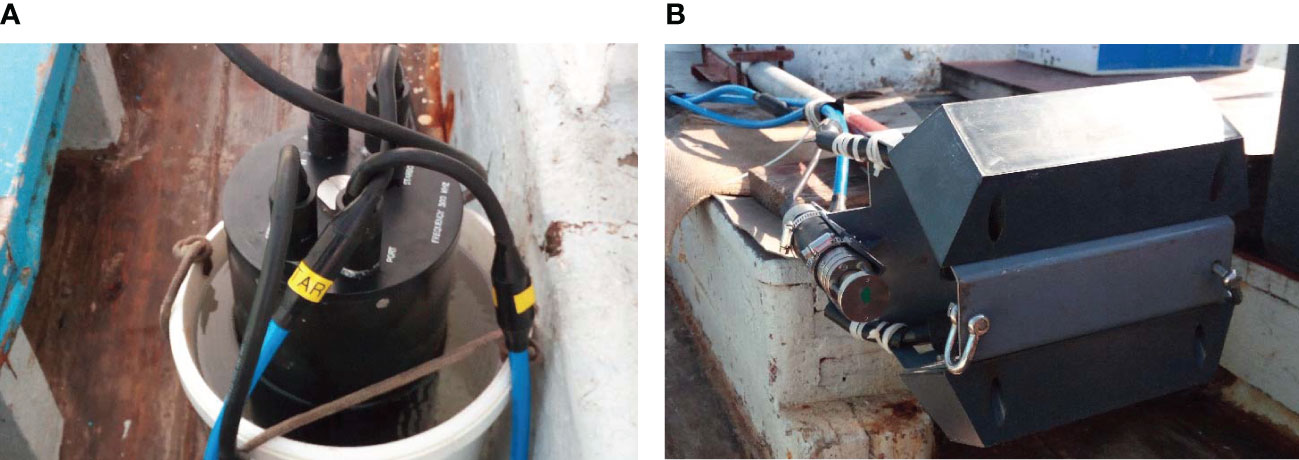
Figure 5 Hardware composition of GS+ (A. Data processing cabin; B. Transducers).
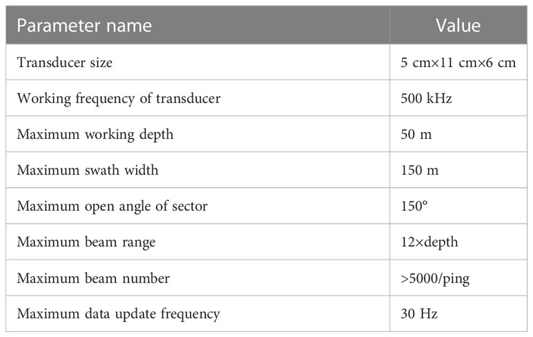
Table 2 Main parameters of GS+.
The sea trial area (1000 m × 900 m), with a depth of 5–40 m, was located close to Qingdao (Figure 6). After the filtering and gridding processes, a DTM with 1 m × 1m grid spacing was created, as shown in Figure 7.
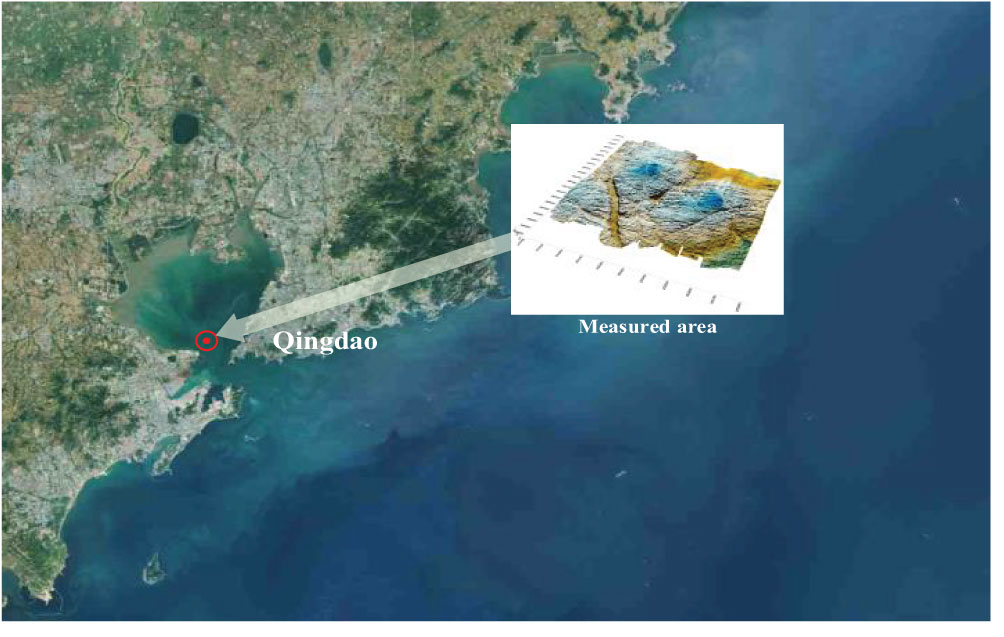
Figure 6 Measured area.
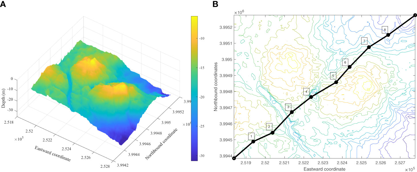
Figure 7 DTM (A: 3D digital terrain B: Contour map).
The path indicated by the black line in Figure 7B is an independent survey line drawn using GS+, which can be used to simulate the MBES data. After the calculation of the terrain characteristics of the survey line that runs through the measured region, eight positioning areas were selected; the size of each area was 100 m × 100 m, and the center of the matching areas is shown in Figure 7B. To compare the richness of the terrain characteristics, the terrain entropies (Wang et al., 2007) of the selected positioning areas were calculated as shown in Table 3.
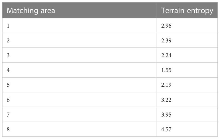
Table 3 Terrain entropy in matching area.
The raw file of the GS+ contains the navigation data of the measured terrain. The navigation data in the raw file are real-time kinematic (RTK) data, and the theoretical positioning accuracy that can be achieved is at the centimeter level. Therefore, real values of terrain positioning can be used through RTK (Yao et al., 2016). Based on the simulation system, the simulation test was divided into algorithm validation and playback simulation tests. An algorithm verification test was used to analyze the main factors affecting the positioning effect by comparing it with typical terrain positioning methods. A playback simulation test was conducted using sea trial data to verify the applicability of the proposed algorithm in an actual marine environment.
4.3 Algorithm validation
For algorithm validation, the real-time terrain was directly intercepted from an independent survey line. For comparison, other simulation tests were performed under same simulation conditions using the UTPM method based on maximum likelihood estimate (MLE), which was proposed in reference (Chen et al., 2012). In this method, the maximum likelihood algorithm is used for correlation analysis of terrain features; for the influence from false peaks of likelihood function at flat bottom area, the Fisher criterion is introduced, and the false peaks are eliminated effectively, which can enhance the discrimination of terrain flat area. The following simulation tests were executed to verify the advantages of the proposed method and analyze the main factors affecting it. The following simulation tests were executed, and the simulation results were obtained based on the mean of the results of 200 simulation tests.
Simulation 1. After the filtering and gridding processes, the size of the real-time terrain was 40×30. By selecting different initial positioning errors (IPEs), the simulation results are shown in Figures 8, 9. The positioning accuracy of the MRF-based method is independent of the terrain entropy, indicating that the MRF-based method has good terrain adaptability. However, the MRF-based method is sensitive to IPEs, and the positioning error increases sharply with increasing IPE. When the IPE reached 30 m, the positioning results were divergent; thus, there were no positioning results. Based on the sequential search principle, the positioning accuracy of the MLE-based method does not worsen with an increase in the IPE; however, it is affected by the richness of the terrain characteristics.
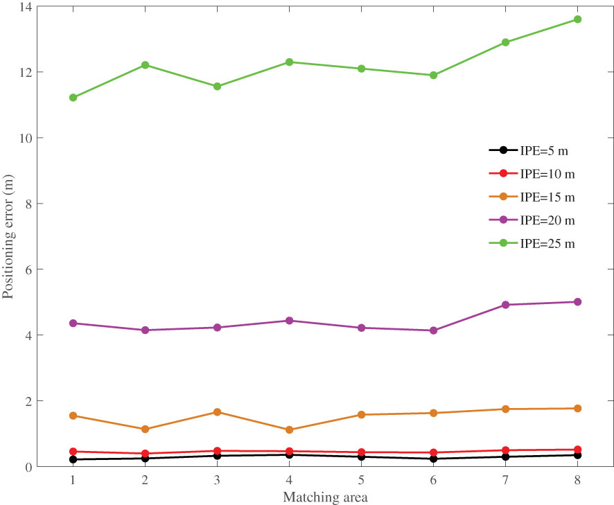
Figure 8 MRF-based results with different IPEs.
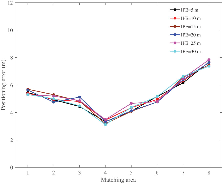
Figure 9 MLE-based results with different IPEs.
Simulation 2. For an IPE of 15 m, different sizes of the real-time terrain were selected; the simulation results are shown in Figures 10, 11. As the amount of real-time terrain data increased, the positioning error of the MRF-based method decreased. This is because an increase in the amount of data increases the range of the real-time terrain, as well as the overlap ratio between the real-time terrain and the local priori DTM, which can result in a more similar neighborhood distribution. In comparison, when the amount of real-time terrain data was relatively small, the positioning error of the MLE-based method decreased as the amount of data increased. Because of the “error averaging” effect, the positioning error cannot always be reduced as the amount of data increases continuously.
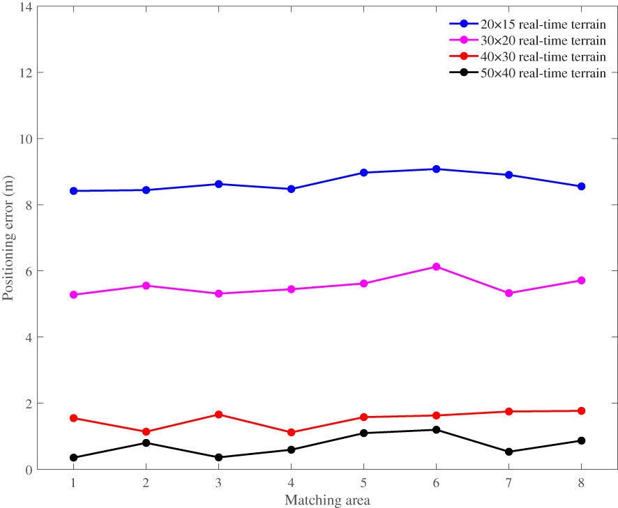
Figure 10 MRF-based results with different real-time terrain.
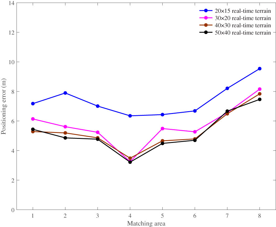
Figure 11 MLE-based results with different real-time terrain.
The above simulation and analysis show that the proposed method is affected by the amount of real-time terrain and IPEs. When the IPEs are small, the positioning accuracy of the proposed method is high. However, as the IPEs increase, the positioning accuracy decreases sharply. Therefore, to obtain higher positioning accuracy, smaller IPEs and larger amounts of real-time terrain data are required. In an actual scenario, owing to the cumulative error of the INS, small IPEs are essentially non-existent. Thus, rough matching positioning is required before the implementation of the proposed algorithm. As a classic terrain correlation method, the mean square difference (MSD) method (Feng, 2004) has the advantages of easy implementation and good real-time performance, and can be used for rough matching positioning.
Simulation 3. For an IPE of 30 m, the size of the real-time terrain was 50×40; the simulation results are shown in Figure 12.
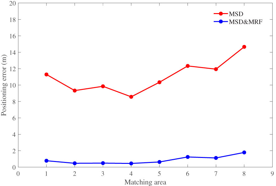
Figure 12 Simulation results with MSD and MRF.
As shown in Figure 12, the positioning accuracy of the MSD-based method is affected by the richness of the terrain characteristics; the positioning errors ranged between 8 and16 m. After the precise positioning based on the MRF method, the positioning errors were less than 2 m. Simulation 2 showed that the positioning results diverged when the IPE reached 30 m. Thus, rough matching positioning is effective. As the covariance calculation in the MLE-based method was not performed in the MSD-based method, the MSD-based method exhibited good real-time performance. In simulation 3, the average positioning time of MSD-based method was less than 0.1 s, and the MLE-based method required about 0.4 s in the same simulation conditions. Thus, the MSD-based method can be used for approximately matching positioning.
4.4 Playback simulation test
The playback simulation implied that the sensor and environmental data were obtained from the sea trials. Based on the acquisition state in the sea trials, the data were read in real-time during the simulation. Because the data were obtained from sea trials, the playback simulation could simulate an actual marine environment; thus, the applicability of the proposed method was verified. The reference navigation data were independent dead-reckoning data with a low-precision DVL that were not corrected using RTK. The playback simulation results are shown in Figure 13.
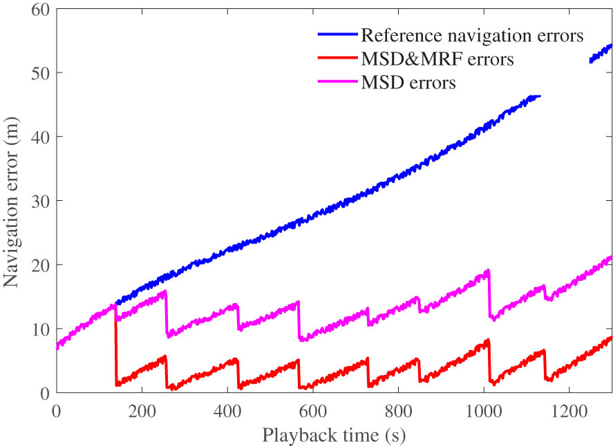
Figure 13 Playback simulation results.
In the simulation, the UUV navigation information was provided by a reference navigation system. When the UUV navigated through the matching area, the terrain-matching navigation system was activated, and the positioning results were used to correct the cumulative errors of the reference navigation system. As shown in Figure 12, after rough matching positioning based on the MSD method, the positioning error was maintained within 15 m, which effectively reduced the initial positioning error for the MRF calculation. After the precise positioning based on the MRF method, the positioning error was less than 2 m in each matching area. Thus, the proposed method can effectively correct the cumulative error of a reference navigation system that can be used for underwater navigation.
5 Conclusions
In this study, an MRF-based UTPM model that achieves high positioning accuracy with small IPEs was developed. The following conclusions were drawn.
1. The proposed method focuses on the strong correlation between terrain data, which can be used to obtain good terrain adaptability.
2. The positioning error of the MRF-based method decreases with an increase in the amount of real-time terrain data. Thus, as much real-time terrain data as possible are required without affecting the real-time performance.
3. The main disadvantage of the MRF-based method is that the initial positioning deviation cannot be extremely large; otherwise, the matching accuracy decreases significantly. Thus, rough matching positioning is required before the implementation of the proposed algorithm.
Data availability statement
The original contributions presented in the study are included in the article/supplementary material. Further inquiries can be directed to the corresponding authors.
Author contributions
PC, TM and LZ contributed to conception and design of this research. XC carried out the database and figures processing. PC and XC performed the MATLAB/Simulink results analysis. PC, YL and TM wrote the first draft of the manuscript. YL revised the finial manuscript. All authors contributed to the article and approved the submitted version.
Funding
This research was funded by the Key Research and Development Program of Shanxi Province (202202020101001), the National Natural Science Foundation of China (51909245, 62003314, 51279221), the Fundamental Research Program of Shanxi Province (202103021224187, 20210302124010, 20210302123050), and the Postgraduate Science and Technology Project of NUC (20221876).
Conflict of interest
The authors declare that the research was conducted in the absence of any commercial or financial relationships that could be construed as a potential conflict of interest.
Publisher’s note
All claims expressed in this article are solely those of the authors and do not necessarily represent those of their affiliated organizations, or those of the publisher, the editors and the reviewers. Any product that may be evaluated in this article, or claim that may be made by its manufacturer, is not guaranteed or endorsed by the publisher.
References
Arashloo S. R., Kittler J. (2011). Energy normalization for pose-invariant face recognition based on MRF model image matching. IEEE Trans. Pattern Anal. Mach. Intell. 33 (6), 1274–1280. doi: 10.1109/TPAMI.2010.209
Bergman N., Ljung L. (1997). Point-mass filter and Cramer-rao bound for terrain-aided navigation (San Diego, California USA, in Proceedings of the 36th IEEE Conference on Decision and Control). 565–570. doi: 10.1109/CDC.1997.650690
Chen P. Y., Chen X. L., Shen J., Ma T. (2021). Single ping filtering of multi-beam sounding data based on alpha shapes. Mar. Technol. Soc. J. 55 (1), 106–114. doi: 10.4031/MTSJ.55.1.9
Chen P. Y., Li Y., Su Y. M., Chen X. L., Jiang Y. Q. (2015a). Underwater terrain positioning method based on least squares estimation for AUV. China Ocean Eng. 29 (6), 859–874. doi: 10.1007/s13344-015-0060-9
Chen P. Y., Li Y., Shen P., Wang R. P., Jiang Y. Q. (2015b). “Comparison and analysis of gridding methods of multi-beam echo sounder,” in Proceedings of the 27th Chinese Control and Decision Conference. 2594–2597.
Chen X. L., Pang Y. J., Li Y., Chen P. Y. (2012). Underwater terrain matching positioning method based on MLE for AUV. Robot 34 (5), 559–565. doi: 10.3724/SP.J.1218.2012.00559
Chen P. Y., Zhang P. F., Ma T., Shen P., Li L., Wang P. R., et al. (2019a). Underwater terrain positioning method using maximum a posteriori estimation and PCNN model. J. Navig. 72 (5), 1233–1253. doi: 10.1017/S0373463319000067
Chen P. Y., Zhang P. F., Chang J. L., Shen P. (2019b). Fast extraction of local underwater terrain features for underwater terrain-aided navigation. J. Mar. Sci. Appl. 18 (3), 334–342. doi: 10.1007/s11804-019-00086-6
Feng Q. T. (2004). The research on new terrain elevation matching approaches and their applicability (Changsha: National University of Defense Technology).
Geman S., Geman D. (1984). Stochastic relaxation, Gibbs distributions, and the Bayesian restoration of images. IEEE Transactions on Pattern Analysis and Machine Intelligence. PAMI-6 (6), 721–741. doi: 10.1109/TPAMI.1984.4767596
Hagen O. K., Anonsen K. B., Saevo T. O. (2012). Low-altitude terrain navigation for underwater vehicles integration of an interferometric side scan sonar improves terrain navigation in low-altitude scenarios. Sea Technol. 53 (6), 10–13.
Huang Y. L., Zhang Y. G., Zhao Y. X. (2019). Review of autonomous undersea vehicle navigation methods. J. Unmanned Veh. Syst. 27 (3), 232–253. doi: 10.11993/j.issn.2096-3920.2019.03.002
Jalving B., Mandt M., Hagen O. K., Phnern F. (2004). Terrain referenced navigation of AUVs and submarines using multibeam echo sounders (Nice, France: Proceedings of UDT European), 1–10.
Jiang Y. Q., Ma D., Li Z. H., Li Y., Ma T., Su X. F., et al. (2022). Cooperative terrain matching navigation of double autonomous underwater vehicles under the Arctic ice. J. Harbin Eng. Univ. 43 (8), 1091–1095. doi: 10.11990/jheu.202106022
Li P. J., Shen G. L., Zhang X. F., Wu J. Q., Xu B. C. (2018). Underwater terrain-aided navigation system based on combination matching algorithm. ISA Trans. 78, 80–87. doi: 10.1016/j.isatra.2017.12.018
Ma T. (2019). AUV bathymetric simultaneous localization and mapping, [Ph.D thesis] (Harbin: Harbin Engineering University).
Ma T., Li Y., Zhao Y. X., Jiang Y. Q., Cong Z., Zhang Q., et al. (2020). An AUV localization and path planning algorithm for terrain-aided navigation. ISA Trans. 103, 215–227. doi: 10.1016/j.isatra.2020.04.007
Matthies L., Okutomi M. (1990). A Bayesian foundation for active stereo vision. (1989, Philadelphia, PA, United States, in Proceedings of 1989 Symposium on Visual Communications, Image Processing, and Intelligent Robotics Systems) 1198, 62–74. doi: 10.1117/12.969965
Nygren I. (2005). Terrain navigation for underwater vehicles (Stockholm: Royal Institute of Technology).
Peng D. D., Zhou T., Li H. S., Zhang W. Y. (2016). Terrain aided navigation for underwater vehicles using maximum likelihood method. (Harbin, China, in Proceedings of 2016 IEEE/OES China Ocean Acoustics Symposium). 1–6. doi: 10.1109/COA.2016.7535750
Salavasidis G., Munafò A., Harris C. A., Prampart T., Templeyon R., Smart M., et al. (2019). Terrain-aided navigation for long-endurance and deep-rated autonomous underwater vehicles. J. Field Robot. 36 (2), 447–474. doi: 10.1002/rob.21832
Salavasidis G., Munafò A., McPhail S. D., Harris C. A., Fenucci D., Pebody M., et al. (2021). Terrain-aided navigation with coarse maps–toward an arctic crossing with an AUV. IEEE J. Ocean. Eng. 46 (4), 1192–1212. doi: 10.1109/JOE.2021.3085941
Shekhovtsov A., Kovtun I., Hlavac V. (2008). Efficient MRF deformation model for no-rigid image matching. Comput. Vis. Image Underst. 112, 91–99. doi: 10.1016/j.cviu.2008.06.006
Teixeira F. C., Quintas J., Maurya P., Pascoal A. (2017). Robust particle filter formulations with application to terrain-aided navigation. Int. J. Adapt. Control Signal Process. 31 (4), 608–651. doi: 10.1002/acs.2692
Wang H., Yan L., Qian X., Zhu M. (2007). Integration terrain match algorithm based on terrain entropy and terrain variance entropy, comput. Technol. Dev. 17 (9), 25–27. doi: 10.3969/j.issn.1673-629X.2007.09.008
Xu B. C., Chen Z. (2005). Novel scene matching algorithm based on Markov random field. Opt. Tech. 31 (60), 849–853. doi: 10.1081/CEH-200044273
Yao Y. B., Hu M. X., Xu C. L. (2016). Positioning accuracy analysis of GPS/BDS/GLONASS network RTK based on DREAMNET. Acta Geod. Cartogr. Sin. 45 (9), 1009–1018. doi: 10.11947/j.AGCS.2016.20160133
Zhang T. W., Han G. J., Lin C., Guizani M., Li H. B., Shu L. (2020a). Integration of communication, positioning, navigation and timing for deep-sea vehicles. IEEE Netw. 34 (2), 121–127. doi: 10.1109/MNET.001.1900294
Zhang T. W., Han G. J., Guizani M., Yan L., Shu L. (2020b). Peak extraction passive source localization using a single hydrophone in shallow water. IEEE Trans. Veh. Technol. 69 (3), 3412–3423. doi: 10.1109/TVT.2020.2968500
Zhao L., Gao N., Huang B. Q., Wang Q. Y., Zhou J. H. (2015). A novel terrain-aided navigation algorithm combined with the TERCOM algorithm and particle filter. IEEE Sens. J. 15 (2), 1124–1131. doi: 10.1109/JSEN.2014.2360916
Keywords: unmanned underwater vehicles, Markov random field (MRF), multi-beam sounding data, terrain-aided navigation, semi-physical simulation
Citation: Chen P, Liu Y, Chen X, Ma T and Zhang L (2023) Underwater terrain positioning method based on Markov random field for unmanned underwater vehicles. Front. Mar. Sci. 10:1201716. doi: 10.3389/fmars.2023.1201716
Received: 07 April 2023; Accepted: 08 May 2023;
Published: 19 May 2023.
Edited by:
Liang Xiao, Dalian Maritime University, ChinaReviewed by:
Jiu Haifeng, Harbin University of Commerce, ChinaPengfei Xu, Hohai University, China
Zaopeng Dong, Wuhan University of Technology, China
Copyright © 2023 Chen, Liu, Chen, Ma and Zhang. This is an open-access article distributed under the terms of the Creative Commons Attribution License (CC BY). The use, distribution or reproduction in other forums is permitted, provided the original author(s) and the copyright owner(s) are credited and that the original publication in this journal is cited, in accordance with accepted academic practice. No use, distribution or reproduction is permitted which does not comply with these terms.
*Correspondence: Pengyun Chen, chenpengyun@nuc.edu.cn; Ying Liu, liuying@hsddyxy.com; Lei Zhang, zhanglei103@hrbeu.edu.cn