On the Geometrically Nonlinear Elastic Response of Class θ = 1 Tensegrity Prisms
 Ida Mascolo
 Ada Amendola
 Giulio Zuccaro
 Luciano Feo1
  Fernando Fraternali
- 1Department of Civil Engineering, University of Salerno, Fisciano, Italy
- 2Department of Structures for Engineering and Architecture, University of Naples Federico II, Napoli, Italy
The present work studies the geometrically nonlinear response of class θ = 1 tensegrity prisms modeled as a collection of elastic springs reacting in tension (strings or cables) or compression (bars), under uniform uniaxial loading. The incremental equilibrium equations of the structure are numerically solved through a path-following procedure, with the aim of modeling the mechanical behavior of the structure in the large displacement regime. Several numerical results are presented with reference to a variety of physical models, which use two different materials for the cables and the bars, and show different aspect ratios associated with either “standard” or “expanded” configurations. An experimental validation of the predicted constitutive response is conducted with reference to a “thick” and a “slender” model, observing rather good theory vs. experiment matching. The given numerical and experimental results highlight that the elastic response of the examined structures may switch from stiffening to softening, depending on the geometry of the system, the magnitude of the external load, and the applied prestress. The outcomes of the current study confirm previous literature results on the elastic response of minimal tensegrity prisms, and pave the way to the use of tensegrity systems as nonlinear spring units forming tunable mechanical metamaterials.
1. Introduction
The research area of mechanical metamaterials has recently paid considerable attention to structures alternating lumped masses and tensegrity units, which feature unconventional behaviors mainly derived from the geometry and the nonlinear response of the units in the large displacement regime (Skelton and de Oliveira, 2010; Fraternali et al., 2012, 2014, 2015a; Micheletti, 2012; Amendola et al., 2014; Davini et al., 2016; Carpentieri and Skelton, 2017; Cimmino et al., 2017; De Tommasi et al., 2017; Fraddosio et al., 2017; Magliozzi et al., 2017; Rimoli and Pal, 2017; Rimoli, 2018). The elastic response of several tensegrity units can be indeed strongly nonlinear, like, e.g., in the case of bistable systems (Micheletti, 2012), tensegrity prisms (Amendola et al., 2014; Fraternali et al., 2015a), and three-dimensional lattices endowed with truncated octahedron cells (Rimoli and Pal, 2017; Rimoli, 2018), just to name a few examples. It has been shown, in particular, that the elastic response of tensegrity prisms may progressively switch from stiffening to softening, through the tuning of mechanical, geometrical, and prestress variables (Amendola et al., 2014; Fraternali et al., 2014, 2015a). For what concerns the wave dynamics of tensegrity metamaterials, recent studies have revealed that systems with stiffening response support compressive strain waves localized in very narrow regions of space (Fraternali et al., 2012; Davini et al., 2016), while softening systems support the propagation of rarefaction waves under impact loading (Herbold and Nesterenko, 2013; Fraternali et al., 2014). The stiffening-type response may be usefully employed to design novel mechanical devices like, e.g., acoustic lenses (Spadoni and Daraio, 2010; Theocharis et al., 2013; Donahue et al., 2014), and/or next-generation sensors for non-destructive structural health monitoring (Rizzo et al., 2014). On the other hand, the softening-type response is very useful for the design of innovative impact mitigation devices that do not rely, or only partially rely, on energy dissipation (Herbold and Nesterenko, 2013; Fraternali et al., 2015a). The study of band gaps in tensegrity-based metamaterials, and their tuning for the design and test of novel waveguides, sound proof layers, and/or vibration protection devices deserves special attention (Theocharis et al., 2013). Other innovative uses of lattice metamaterials can be found in Amendola et al. (2017), Colombi et al. (2017), Feo et al. (2017), Genoese et al. (2017), Jiang et al. (2017), La Salandra et al. (2017), Naddeo et al. (2017a,b), Tallarico et al. (2017), Yin et al. (2017), Miniaci et al. (2018), and references therein.
A new type of tensegrity unit, named class θ = 1 tensegrity prism, has been recently designed and studied in Bieniek (2017a,b). Such a unit is formed by the superimposition of two sets of three bars, which may be thought as the compressive members of two minimal tensegrity prisms placed one over the other. Those bars are connected each other through six internal strings. The structure is completed by two terminal bases formed by triangular sets of external strings (or cables). The symbol θ is used to mimic the shape of the structure, formed by both external and internal cables (Modano et al., 2018). Structures of class θ = 1 are formed by one single set of internal strings/cables.
The numerical and analytical results presented in Modano et al. (2018) deal with the search for free-standing configurations of tensegrity θ = 1 prisms, in correspondence with different geometries of the following three sets of members: external strings with equal length ℓ; internal strings with equal length c and cross cables with equal length v. The length of the bars b is a function of such design variables (Bieniek, 2017a,b). The study presented in Modano et al. (2018) also includes the analysis of the kinematic problem of tensegrity θ prisms, with the aim of finding the infinitesimal mechanisms of these structures from the freestanding configuration. It has been proven that the number of infinitesimal mechanisms of class θ = 1 tensegrity prisms (Modano et al., 2018) is much larger than that exhibited by minimal (or standard) tensegrity prisms (Fraternali et al., 2015a).
The present work studies the elastic response of tensegrity θ = 1 prisms in the large displacement regime induced by a uniform compression loading, which follows from the application of equal vertical forces to the nodes of the top base, while keeping the bottom base at rest. We start by analyzing physical models of the examined structures, which are formed by threaded steel bars and Spectra® cables, and determining the corresponding freestanding configurations on the basis of the approach presented in Modano et al. (2018) (Section 2). A path-following approach is next formulated, in order to study the elastic response of class θ = 1 tensegrity prisms in the large displacement regime under arbitrary loading conditions (Section 3). Section 4 applies such a procedure to a numerical study on the elastic response of different tensegrity θ units under compression loading. An experimental validation of standard thick and slender models under quasi-static axial compression has been carried out in Section 4 with reference to “thick” and “slender” models under quasi-static axial compression, observing a good agreement between theory and experiment (Section 5). The results presented in Sections 4 and 5 highlight that tensegrity θ = 1 prisms can exhibit an elastic response that can switch from softening to stiffening, in analogy with the response theoretically and experimentally observed in minimal tensegrity prisms (Amendola et al., 2014; Fraternali et al., 2015a). Such a multifaceted elastic response can be usefully exploited for the design and construction of novel tensegrity metamaterials, as it is emphasized in the concluding remarks drawn in Section 6.
2. Physical Models of Class θ = 1 Prisms
2.1. Freestanding Configurations
We examine in the present study a collection of physical models of tensegrity θ = 1 prisms, with either thick (v ≈ λ) or slender (v≥2λ) aspect ratios. On adopting the labeling and nomenclature introduced in Figure 1 and Modano et al. (2018), for each of such a shape we examine both “standard” and “expanded” configurations, which correspond to the values of the design variables λ, v, and c shown in Figure 2. In the standard prisms, the internal strings 7-10, 10-9, 9-12, 12-8, 8-11, and 11-7 lie in the interior of the region delimited by the vertical strings 1-4, 2-5, and 3-6, while in the expanded systems the internal strings run externally with respect to the vertical strings. Figure 2 illustrates the freestanding configurations of the units analyzed in this work (labeled S1, S2, S3, and S4) that were obtained through the approach formulated in Modano et al. (2018), which searches for the values of two design variables α and β that ensure existence of a self-equilibrated state of stress of the structure under zero external forces. The variable α measures the twisting angle between the top and bottom bases of the prism, while β measures the inclination of the inner cables with respect to the horizontal plane (Figure 1).
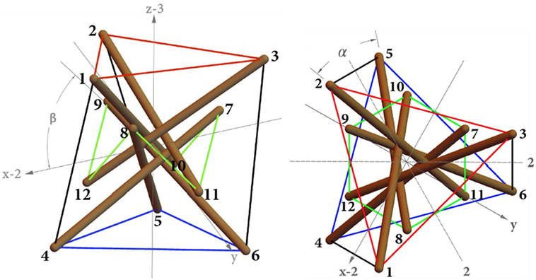
Figure 1. Reference configuration of a standard tensegrity θ = 1 prism.
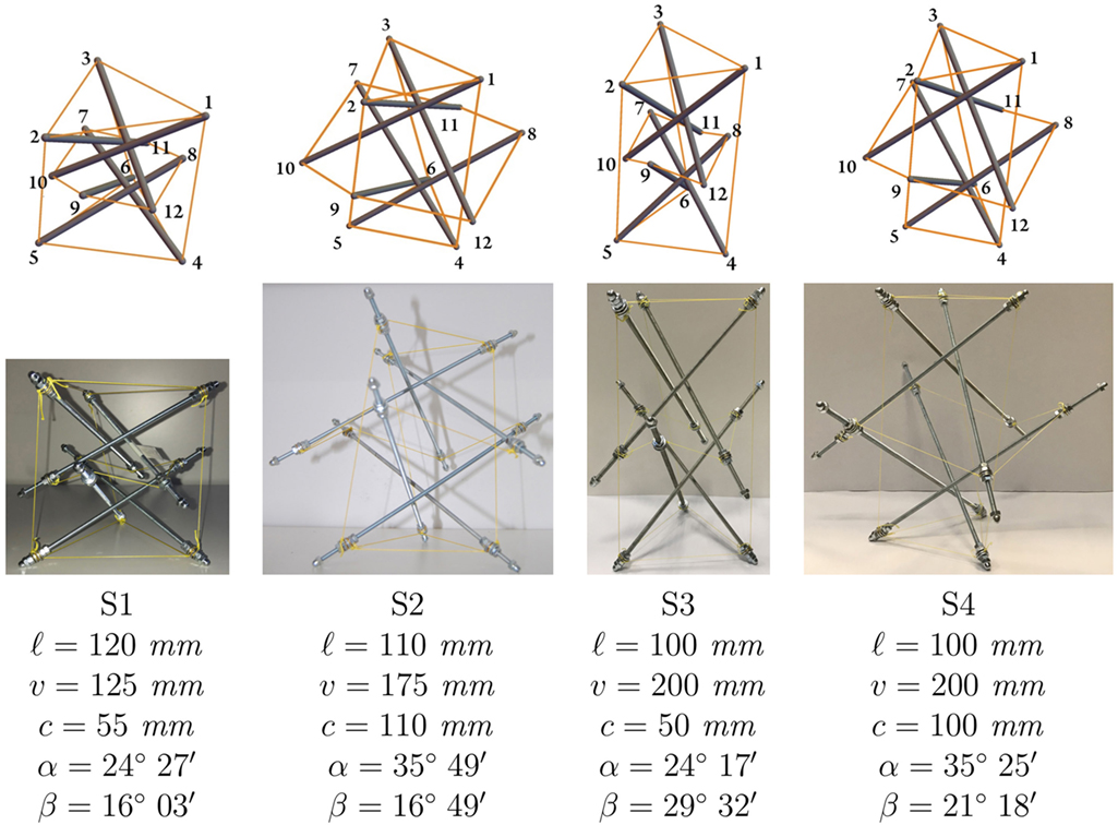
Figure 2. Graphical (top) and physical (bottom) models of the systems analyzed in the present study: standard thick unit (S1); expanded thick unit (S2); standard slender unit; (S3) expanded thick unit (S4).
Figure 2 provides the “self-equilibrium values” of such variables, while Table 1 gives the corresponding self-stress states, as a function of the force density in the top and bottom strings xt (here assumed as the independent prestress variable, cf. Modano et al. (2018)). The latter can be computed as: xt = kt p0/(1 + p0), where kt denotes the axial stiffness of top and bottom strings (see Section 3), and p0 denotes the prestrain of such elements in the freestanding configuration (Fraternali et al., 2015a).
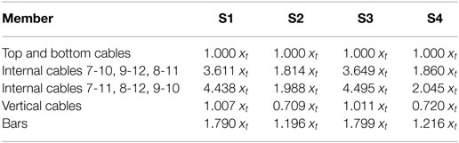
Table 1. Force densities (per unit length) characterizing the self-stress acting in the systems of Figure 2 (forces positive when tensile in cables, and when compressive in bars).
2.2. Assembling Methods
The physical models examined in the present work make use of M4 threaded bars, made out of white zinc-plated grade 8.8 steel (BS ISO 68-1:1998, 1998), and cables consisting of braided Spectra® fibers commercially produced by PowerPro (2018). Such elements were assembled through the following procedure, which generalizes that given in Amendola et al. (2014) for minimal tensegrity prisms (cf. Figures 3–6):
• Insertion and securing of Spectra® cables into eyelets and washers to be passed through the threaded bars (Figures 3A–C);
• assembling of three distinct networks of Spectra® cables: two equilateral triangles with side length ℓ connecting the external nodes (Figure 3D), and a regular hexagon with side length c connecting the internal nodes;
• cutting of three vertical cables with equal length v equipped with eyelets and washers to be passed through the threaded bars (Figure 3E);
• insertion of the eyelets and washers attached to the top, bottom, and internal cables into the threaded bars, and their securing with two additional steel nuts and a washer (Figure 4A);
• insertion of the eyelets and washers attached to the vertical cables into the threaded bars, and their securing with an acorn steel nut, a washer and a steel nut (Figure 4B);
• tightening of the cables and application of the desired prestress through suitable fastening of the steel nuts (Figures 4C and 5).
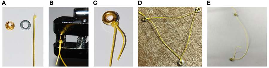
Figure 3. Photographs illustrating the connection and securing of Spectra® cables to eyelets and washers to be passed through the threaded bars (A–C); a triangular network of cables (D); and a vertical cable (E).
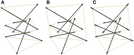
Figure 4. Assembling steps: mounting of top, bottom, and inner cables on the bars (A); insertion of vertical cables (B); tightening of the cables (C).
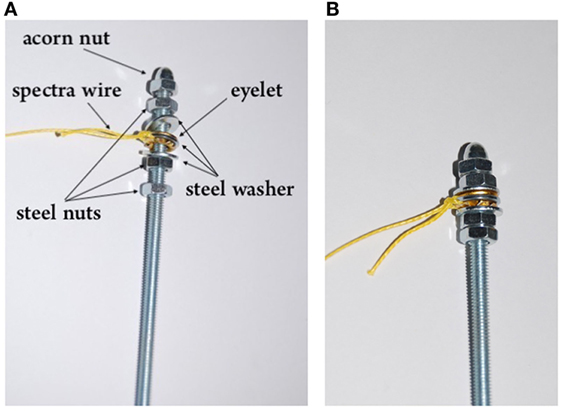
Figure 5. Bar equipment: photographs of a bar before (A) and after (B) the fastening of the steel nuts.
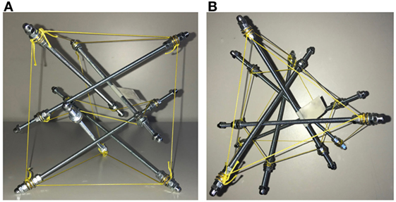
Figure 6. Standard thick prism: (A) axonometric view and (B) top view.
Figure 6 shows an assembled thick prism (system S1). The state of prestress acting in the physical models S1 and S3 was determined via identification of the experimental response illustrated in Section 5.
3. Elastic Response Under Large Displacements
The present section generalizes the procedure formulated in Fraternali et al. (2015a) with the aim of studying the elastic response in the large displacement regime of a generic lattice structure formed by an arbitrary number m of members. Assuming that such a structure responds in pure stretching mode, we model the generic member, say the ith one, as a linear elastic spring governed by the following constitutive law
where ti denotes the axial force carried by the member, li denotes its length in the current configuration, denotes the rest length in the stress-free (or natural) configuration, and ki denotes the elastic stiffness constant. By setting in the reference configuration, one induces an initial axial deformation of the member, which is expected to significantly affect the incremental response of the structure from such a configuration (cf. Section 4). Upon neglecting the change of the cross section area during the lattice deformation, we define the stiffness constant ki as follows
where Ei is the Young’s modulus of the material, and Ai is the cross section area. In the case of cable elements, we set ki = 0 when the cable gets slack, i.e., when it results . All the systems examined in the present study employ only two materials and cross-sections: one for the bars and one for the cables. As anticipated, we use M4 threaded bars made out of white zinc plated grade 4.8 steel (DIN 976-1) with a nominal cross section area 8.78 mm2, and 203.53 GPa Young’s modulus. Such bars are connected each other through Spectra® cables with 0.76 mm diameter in systems S1 and S2; 0.36 mm diameter in systems S3 and S4; and 30.00 GPa Young’s modulus. The mechanical properties of the Spectra® fibers were determined through tensile tests carried out at the Structural Engineering Testing Hall (Strength) of the University of Salerno. The yield stress of the cables was measured approximatively equal to 2 GPa, with the aim of verifying that such members actually respond in the elastic regime in correspondence with the numeric simulations presented in Section 4.
The equilibrium equations of the structure under examination can be written in the following scalar form
where the index i runs from one to the total number of members m, while the index j runs from one to the total number of degrees of freedom ndof = 3 × n, n denoting the number of nodes. In equation (3), is a scalar multiplier of the vector w with entries wj (j = 1, …, ndof), which describes the distribution of the external load; denotes the generic entry of the nodal displacement vector from the current configuration; and the quantities give the cosine directors of the members’ axes (it clearly results if the kinematics of the ith member is not affected by the jth degree of freedom).
3.1. Path-Following Procedure
Let us study the elastic response of a class θ = 1 tensegrity prisms under an arbitrary loading condition, which is characterized by the control parameter and the state variable . The solution of such a problem in the large displacement regime can be achieved through a continuation method in which a predictor step is followed by a suitable number of iteration steps.
We analyze the incremental response of the structure under examination from an initial configuration , when the control variable is suitably varied, so as to match a given constraint equation , which defines the adopted loading strategy (Fraternali et al., 2015a).
The Newton-Raphson linearization of equation (3) leads us to the following approximation of the increment of the residual drifting errors of the equilibrium problem
where (j,k = 1, …, ndof) is the generic entry of tangent stiffness matrix given by Guest (2006), Schenk et al. (2007), Fraternali et al. (2015b), and Modano et al. (2018)
By setting to zero the residuals ri at , , we are led to the system of incremental equations
It is convenient to make use of the following decomposition of the increments of the state variables: , and being the partial solutions of the following linear systems
The linearization of the constraint equation gives
from which we obtain
In the case of displacement control, we write , where is a prescribed value of a given displacement component. Such a position leads us to reduce equation (9) to the following form
We embed the above solution strategy into a step-by-step, incremental procedure that produces a sequence of updates , of the state and control variables along a given loading path. The algorithm presented in Table 2 describes the procedure ruling the sth step of such a strategy, where tol denotes a given zero tolerance of the residual vector.
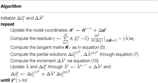
Table 2. Path-following algorithm.
4. Numerical Results
The present section presents an application of the algorithm presented in Section 3.1 to the uniform compression loading of the systems illustrated in Figure 2. The examined loading condition consists of three equal vertical forces applied to the top nodes, with resultant F (positive if directed downward), while the bottom base is at rest. It is easily verified that the symmetry of such a loading condition and the geometric symmetry of the systems in Figure 2 induces a uniform compression of the structure, which is characterized by equal vertical displacements w of the nodes of the top base (also assumed positive if directed downward).
Figures 7–10 illustrate the force F vs. w responses of systems S1–S4, which were numerically predicted through the path-following procedure illustrated in Section 3.1. We employ a hollow circle mark “°” to denote the first point of the F–w response where the vertical strings get slack, and a black circle mark “•” to denote the first point at which the bars fail due to buckling (“local buckling” occurring when the axial force carried by the generic bar equals the Euler buckling load). Obviously, the portions of the F–w curves in Figures 7–10 that are placed beyond the points marked with the “•” symbol are just theoretical, since the path-following algorithm presented in Section 1 actually accounts for the strings getting slack, but does not model the postyielding and postbuckling responses of bars and strings. We didn’t observe string yielding in the simulations presented hereafter.
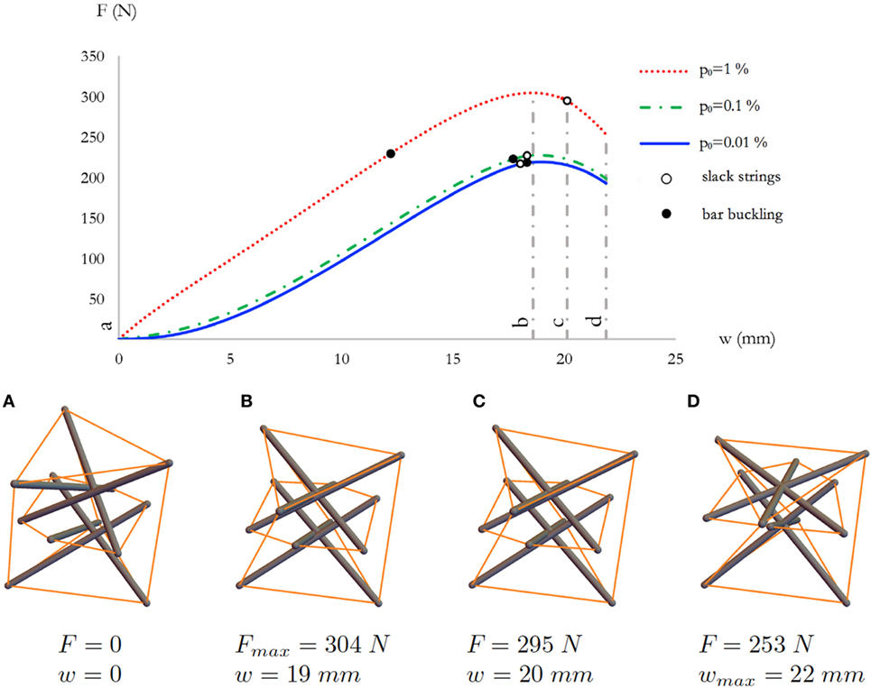
Figure 7. Top: force-displacement curves of system S1 for different value of the prestrain p0. Bottom: sequence of deformed configurations (A–D) for p0 = 1%.
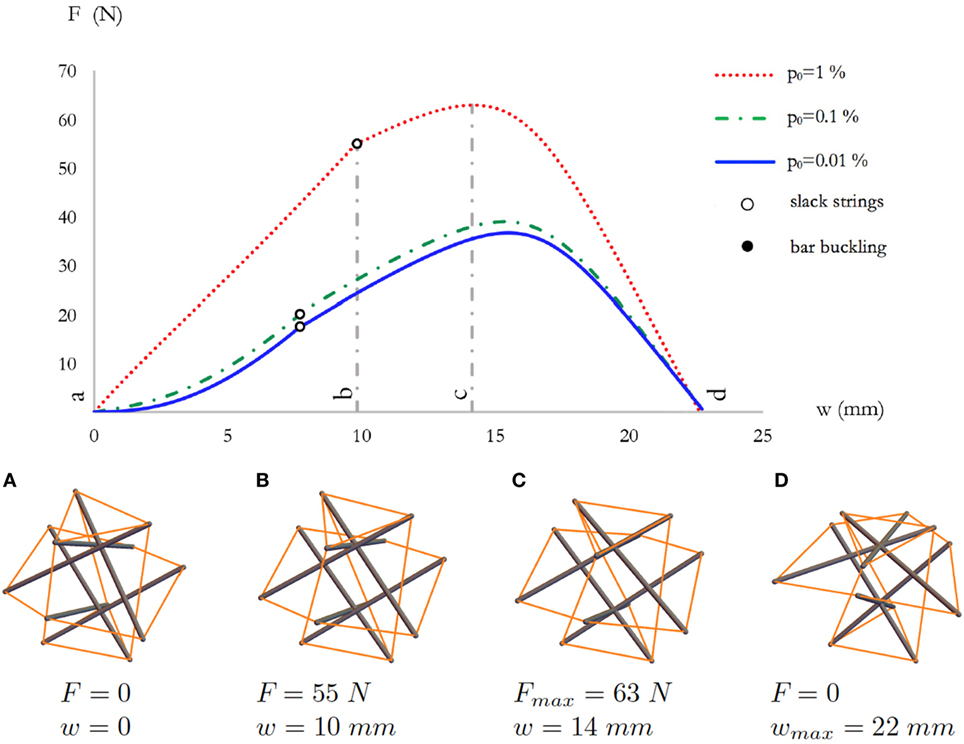
Figure 8. Top: force-displacement curves of system S2 for different value of the prestrain p0. Bottom: sequence of deformed configurations (A–D) for p0 = 1%.
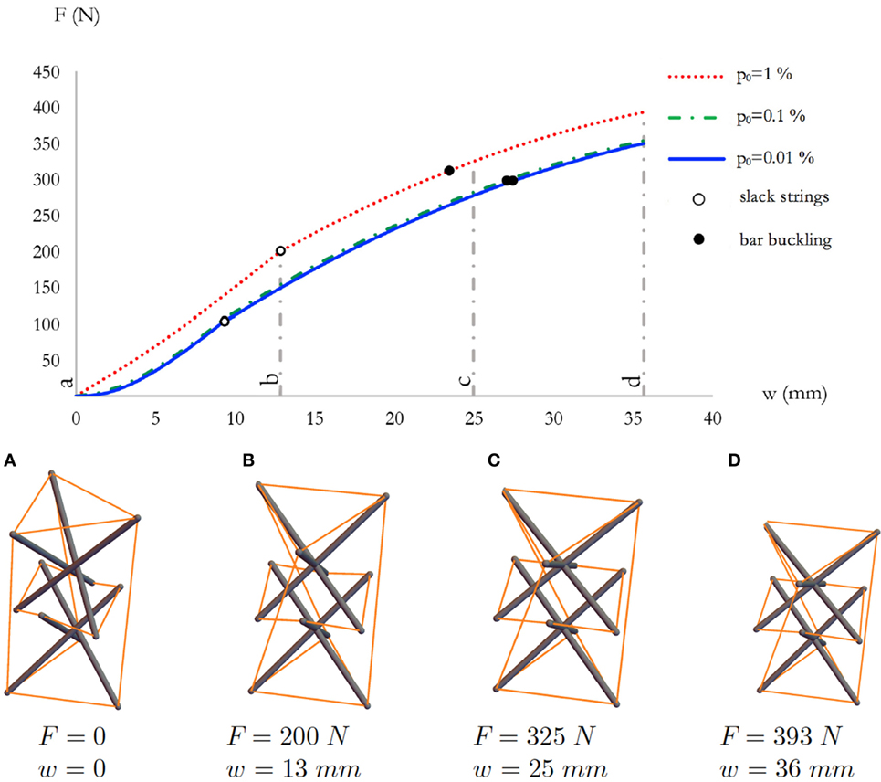
Figure 9. Top: force-displacement curves of system S3 for different value of the prestrain p0. Bottom: sequence of deformed configurations (A–D) for p0 = 1%.
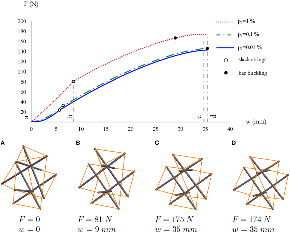
Figure 10. Top: force-displacement curves of system S4 for different value of the prestrain p0. Bottom: sequence of deformed configurations (A–D) for p0 = 1%.
When the prestrain p0 that characterizes the freestanding configuration is equal to 0.01 or 0.1%, the response of the standard thick system S1 shown in Figure 7 highlights a stiffening behavior near the origin (small displacements from the freestanding configuration), which corresponds to an increasing slope to the F–w curve (giving the effective axial stiffness Kw of the structure) for increasing w displacements. The above small-displacement response is first followed by a “stiffness-softening” branch (Kw decreasing with increasing w), and next by a “force-softening” branch (F decreasing with increasing w, or, equivalently, kw < 0). Slightly different is the response of the S1 system under the action of a prestrain p0 = 1%, since, in such a case, the F–w curve does not show an initial stiffening branch, but instead exhibits a stiffness-softening branch followed by a force-softening branch (Figure 7). The force-softening branch leads the structure to a snap-buckling collapse phenomenon (hereafter referred to as “global buckling”), which initiates when it results Kw = 0 (see Figure 7D). For p0 ≤ 0.01%, the local buckling failure occurs slightly before global buckling, while for p0 = 1% local buckling noticeably anticipates global buckling.
The F–w response of the expanded thick system S2 shown in Figure 8 reveals that such a system features compressive behavior qualitatively similar to that exhibited by the standard thick system S1, even if the S2 system carries significantly lower forces than system S1. It is worth noting that the vertical strings of the S2 system get slack much earlier than those of the S1 system (i.e., for lower values of the vertical displacement w), giving rise to bending points of the F–w curve (Figure 8). In the S2 system, global buckling anticipates local buckling, differently from what happens in the case of system S1 (compare Figures 7 and 8).
The slender system S3 exhibits the force–displacement response that is illustrated in Figure 9. Such a response is again characterized by the occurrence of local buckling before global buckling, like in the case of the thick system S1. In the S3 system, the F–w curves corresponding to different values of p0 are more close to each other, at least up to p0 = 1%, and the structure is able to accommodate larger axial displacements, as compared to the thick systems S1 and S2. We interrupted the F–w curves in Figure 9 when the bars were close to touch each other (cf. Figure. 9D). The force–displacement response of the expanded slender system S4 in Figure 10 looks qualitatively similar to that of the S3 system, with the difference that the expanded system S4 carries markedly lower axial forces F than the S3 system. In the case of system S4, local buckling does not occur up to the configuration when the bars touch each other. Moreover, in such a system, the strings gets slack for lower values of w, as compared to system S3 (cf. Figures 9 and 10).
5. Experimental Validation
We conducted an experimental validation of the numerical results presented in the previous section with reference to the standard thick system S1 (cf. Figure 11), and the standard slender system S3. Quasistatic compression tests on such systems were performed at the Strength’s partner laboratory Geo Consult s.r.l. (Avellino, Italy) on a Matest® electromechanical testing system equipped with 50 kN load cell, employing displacement control with loading rate of 4 mm/min. The tested structures were placed on a rotating lubricated base that allowed for relative twisting of the top and bottom bases. A 140 g drywall plate was placed on the top base of the tested sample to ensure a uniform distribution of the load applied by the testing machine, as shown in Figure 11. Friction effects were minimized by accurately lubricating the contacts between bars and cables, as well as the junctions between the bottom and top nodes and the plates that are in contact with the terminal bases. Time, force and displacement data were acquired with 4 mm/min sampling rate.
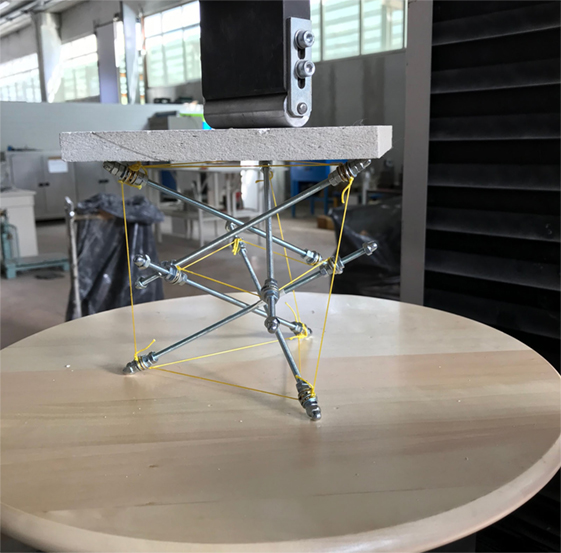
Figure 11. System S1 under testing.
Figure 12 shows a comparison between the predicted F vs. w curves of the thick system S1, for different values of p0, and the observed experimental response. The experimental response is rather close to the theoretical curves corresponding to p0 = 0.01% and p0 = 0.1%, and shows an initial stiffening branch followed by a stiffness-softening branch. A theory vs. experiment comparison for the response of the slender model S3 is shown in Figure 13. Also in the case of the S3 system, as well as in system S1, a stiffening branch turns into a softening branch of the experimental response, and such a response well matches the numerical F vs. w curves for p0 = 0.01% and p0 = 0.1% (Figure 13). We are therefore led to conclude that the prestress applied to the S1 and S3 specimens is characterized by a prestrain p0 of the strings in the range 0.01/0.1%. In all the tested specimens, the bars touched each other before global buckling could occur. Such an anticipated “locking” of the real structures, as compared to the theoretical models, follows from the actual, nonzero thickness of the bars in the real prisms.
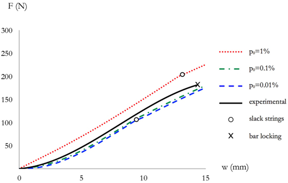
Figure 12. Experimental vs. numerical force–displacement responses of the thick system S1.
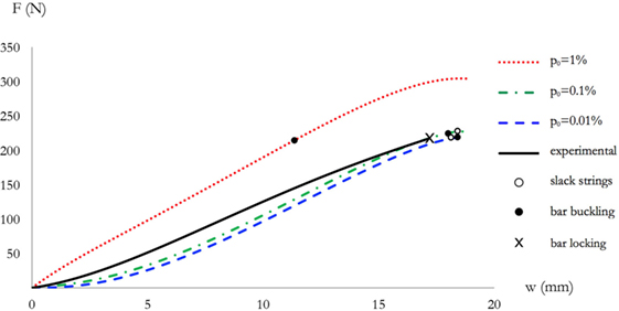
Figure 13. Experimental vs. numerical force–displacement responses of the slender system S3.
6. Concluding Remarks
We have formulated a path-following approach to the elastic problem of tensegrity prisms of class θ = 1 in the large displacement regime. The proposed numerical procedure (Section 3) has been applied to predict the response of the several physical models of the examined structures under uniform compressive loading (Section 4). Such a study has revealed that tensegrity θ = 1 prisms exhibit compressive response characterized by alternating stiffening and softening branches, with a stiffness-softening response leading the structure to vertical collapse, due to a global snap-buckling phenomenon. The initial stiffening branch may be absent under the action of large or moderately large values of the applied prestress. In the examined standard systems (internal strings running in the interior of the region delimited by the vertical strings), local bar buckling occurs before global buckling, while the opposite happens in the thick expanded system (internal strings running externally to the vertical strings). In the expanded systems, the vertical strings get slack for lower values of the vertical displacement, as compared to standard systems. The response of slender prisms is sensitive to a locking phenomenon occurring with the bars touching each other, which anticipates global buckling. An experimental validation of the theoretical models has been conducted with reference to standard thick and slender systems, observing rather good theory vs. experiment matching. Anticipated locking occurred in the experimentally tested samples, as compared to the theoretical models, due to the non-negligible size of the bars.
The results of the present study confirm previous theoretical and experimental results relative to minimal tensegrity prisms (Amendola et al., 2014; Fraternali et al., 2015a), highlighting that tensegrity prisms of class θ may be employed as nonlinear springs connecting lumped masses in tensegrity metamaterials (Fraternali et al., 2014; Modano et al., 2018). It is worth noting that the high number of infinitesimal mechanisms characterizing the response of tensegrity θ prisms suggests that such structures may be able to exhibit geometrically nonlinear response under a wide range of loading conditions (Modano et al., 2018).
Additional mechanical uses of the units analyzed in the present article, which will be studied in future work, aim to reveal band gaps in tensegrity-based metamaterials and to exploit the possibility of their tuning for the design and test of novel waveguides, sound proof layers and vibration protection devices (Modano et al., 2018). Such systems will be tunable by varying the unit’s parameters for both the initial static precompression of the constituent units (internal selfstress) and the whole structure (external prestress). Additional future work will include the modeling of postyielding and postbuckling phenomena in bars and strings, as well as the description of the unit response after the structure’s locking occurs.
Author Contributions
IM led the phases related to the construction of the experiments and collaborated to the mechanical and numerical modeling. AA led the mechanical and numerical modeling and collaborated to the execution of the experiments. GZ supervised the mechanical modeling phases. LF supervised the experimental phases. FF supervised and directed all the phases of the project.
Conflict of Interest Statement
The authors declare that the research was conducted in the absence of any commercial or financial relationships that could be construed as a potential conflict of interest.
Acknowledgments
IM gratefully acknowledges financial support from the PhD School in Civil Engineering at the University of Salerno. The authors wish to thank Erminio Pagliuca from the Geoconsult Laboratory of Manocalzati (Avellino, Italy) for technical help and assistance with the tests presented in Section 5.
References
Amendola, A., Benzoni, G., and Fraternali, F. (2017). Non-linear elastic response of layered structures, alternating pentamode lattices and confinement plates. Compos. Part B Eng. 115, 117–123. doi: 10.1016/j.compositesb.2016.10.027
Amendola, A., Fraternali, F., Carpentieri, G., de Oliveira, M. C., and Skelton, R. E. (2014). Experimental investigation of the softening-stiffening response of tensegrity prisms under compressive loading. Compos. Struct. 117, 234–243. doi:10.1016/j.compstruct.2014.06.022
Bieniek, Z. W. (2017a). “The self-equilibrium configurations for the class-theta triangular tensegrity prism,” in Proceedings of the XXIII Conference of the Italian Association of Theoretical and Applied Mechanics (XXIII AIMETA), GECHI EDIZIONI by Centro Servizi dâĂŹAteneo S.r.l., Vol. 3 (Salerno), 1103–1109.
Bieniek, Z. W. (2017b). The self-equilibrium problem of the class-theta tetrahedral tensegrity module. Compos. Part B Eng. 115, 21–29. doi:10.1016/j.compositesb.2016.10.054
Carpentieri, G., and Skelton, R. E. (2017). On the minimal mass design of composite membranes. Compos. Part B Eng. 115, 244–256. doi:10.1016/j.compositesb.2016.09.091
Cimmino, M. C., Miranda, R., Sicignano, E., Ferreira, A. J. M., Skelton, R. E., and Fraternali, F. (2017). Composite solar façades and wind generators with tensegrity architecture. Compos. Part B Eng. 115, 275–281. doi:10.1016/j.compositesb.2016.09.077
Colombi, A., Craster, R. V., Colquitt, D., Achaoui, Y., Guenneau, S., Roux, P., et al. (2017). Elastic wave control beyond band-gaps: shaping the flow of waves in plates and half-spaces with subwavelength resonant rods. Front. Mater. 3, 1–10. doi:10.3389/fmech.2017.00010
Davini, C., Micheletti, A., and Podio-Guidugli, P. (2016). On the impulsive dynamics of T3 tensegrity chains. Meccanica 51, 2763–2776. doi:10.1007/s11012-016-0495-y
De Tommasi, D., Marano, G. C., Puglisi, G., and Trentadue, F. (2017). Morphological optimization of tensegrity-type metamaterials. Compos. Part B Eng. 115, 182–187. doi:10.1016/j.compositesb.2016.10.017
Donahue, C., Anzel, P. W. J., Bonanomi, L., Keller, T. A., and Daraio, C. (2014). Experimental realization of a nonlinear acoustic lens with a tunable focus. Appl. Phys. Lett. 104, 014103. doi:10.1063/1.4857635
Feo, L., Fraternali, F., and Skelton, R. E. (2017). Special issue on composite lattices and multiscale innovative materials and structures. Compos. Part B Eng. 115, 1–2. doi:10.1016/j.compositesb.2016.10.066
Fraddosio, A., Marzano, S., Pavone, G., and Piccioni, M. D. (2017). Morphology and self-stress design of V-expander tensegrity cells. Compos. Part B Eng. 115, 102–116. doi:10.1016/j.compositesb.2016.10.028
Fraternali, F., Carpentieri, G., and Amendola, A. (2015a). On the mechanical modeling of the extreme softening/stiffening response of axially loaded tensegrity prisms. J. Mech. Phys. Solids 74, 136–157. doi:10.1016/j.jmps.2014.10.010
Fraternali, F., De Chiara, E., and Skelton, R. E. (2015b). On the use of tensegrity structures for kinetic solar facades of smart buildings. Smart. Mater. Struct. 24, 1–10. doi:10.1088/0964-1726/24/107105032
Fraternali, F., Carpentieri, G., Amendola, A., Skelton, R. E., and Nesterenko, V. F. (2014). Multiscale tunability of solitary wave dynamics in tensegrity metamaterials. Appl. Phys. Lett. 105, 201903. doi:10.1063/1.4902071
Fraternali, F., Senatore, L., and Daraio, C. (2012). Solitary waves on tensegrity lattices. J. Mech. Phys. Solids 60, 1137–1144. doi:10.1016/j.jmps.2012.02.007
Genoese, A., Genoese, A., Rizzi, N. L., and Salerno, G. (2017). On the derivation of the elastic properties of lattice nanostructures: the case of graphene sheets. Compos. Part B Eng. 115, 316–329. doi:10.1016/j.compositesb.2016.09.064
Guest, S. D. (2006). The stiffness of prestressed frameworks: a unifying approach. Int. J. Solids Struct. 43, 842–854. doi:10.1016/j.ijsolstr.2005.03.008
Herbold, E. B., and Nesterenko, V. F. (2013). Propagation of rarefaction pulses in discrete materials with strain-softening behavior. Phys. Rev. Lett. 110, 144101. doi:10.1103/PhysRevLett.110.144101
Jiang, S., Sun, F., Zhang, X., and Fan, H. (2017). Interlocking orthogrid: an efficient way to construct lightweight lattice-core sandwich composite structure. Compos. Struct. 176, 55–71. doi:10.1016/j.compstruct.2017.05.029
La Salandra, V., Wenzel, M., Bursi, O. S., Carta, G., and Movchan, A. B. (2017). Conception of a 3D metamaterial-based foundation for static and seismic protection of fuel storage tanks. Front. Mater. 4, 1–13. doi:10.3389/fmats.2017.00030
Magliozzi, L., Micheletti, A., Pizzigoni, A., and Ruscica, G. (2017). On the design of origami structures with a continuum of equilibrium shapes. Compos. Part B Eng. 115, 144–150. doi:10.1016/j.compositesb.2016.10.023
Micheletti, A. (2012). Bistable regimes in an elastic tensegrity system. P. Roy. Soc. 469, 201300520. doi:10.1098/rspa.2013.0052
Miniaci, M., Mazzotti, M., Radzienski, M., Kherraz, N., Kudela, P., Ostachowicz, W., et al. (2018). Experimental observation of a large low-frequency band gap in a polymer waveguide. Front. Mater. 5, 1–9. doi:10.3389/fmats.2018.00008
Modano, M., Mascolo, I., Fraternali, F., and Bieniek, Z. (2018). Numerical and analytical approaches to the self-equilibrium problem of class θ = 1 tensegrity metamaterials. Front. Mater. 5, 1–8. doi:10.3389/fmats.2018.00005
Naddeo, F., Naddeo, A., and Cappetti, N. (2017a). Novel ‘load adaptive algorithm based’ procedure for 3D printing of lattice-based components showing parametric curved micro-beams. Compos. Part B Eng. 115, 51–59. doi:10.1016/j.compositesb.2016.10.037
Naddeo, F., Naddeo, A., and Cappetti, N. (2017b). Novel ‘load adaptive algorithm based’ procedure for 3D printing of cancellous bone-inspired structures. Compos. Part B Eng. 115, 60–69. doi:10.1016/j.compositesb.2016.10.033
PowerPro. (2018). Ultra-strong braided Spectra® Fiber. [Online]. Available at: http://www.powerpro.com/content/powerpro-north-america/en/home/products/powerpro.html. (accessed February 10, 2018).
Rimoli, J. J. (2018). A reduced-order model for the dynamic and post-buckling behavior of tensegrity structures. Mech. Mater. 116, 146–147. doi:10.1016/j.mechmat.2017.01.009
Rimoli, J. J., and Pal, R. K. (2017). Mechanical response of 3-dimensional tensegrity lattices. Compos. Part B Eng. 115, 30–42. doi:10.1016/j.compositesb.2016.10.046
Rizzo, P., Ni, X., Nassiri, S., and Vandenbossche, J. (2014). A solitary wave-based sensor to monitor the setting of fresh concrete. Sensors (Basel) 14, 12568–12584. doi:10.3390/s140712568
Schenk, M., Guest, S. D., and Hender, J. L. (2007). Zero stiffness tensegrity structure. Int. J. Solids Struct. 44, 6569–6583. doi:10.1016/j.ijsolstr.2007.02.041
Spadoni, A., and Daraio, C. (2010). Generation and control of sound bullets with a nonlinear acoustic lens. Proc. Natl. Acad. Sci. U.S.A. 107, 7230–7234. doi:10.1073/pnas.1001514107
Tallarico, D., Trevisan, A., Movchan, N. V., and Movchan, A. B. (2017). Edge waves and localization in lattices containing tilted resonators. Front. Mater. 4, 1–13. doi:10.3389/fmats.2017.00016
Theocharis, G., Boechler, N., and Daraio, C. (2013). “Nonlinear phononic structures and metamaterials,” in Acoustic Matematerials and Phononic Crystals, Vol. 173, ed. P. A. Deymier (Berlin: Springer Series in Solid State Sciences), 217–251.
Keywords: class θ tensegrity prisms, large displacements, path-following, elastic softening, elastic stiffening, mechanical metamaterials
Citation: Mascolo I, Amendola A, Zuccaro G, Feo L and Fraternali F (2018) On the Geometrically Nonlinear Elastic Response of Class θ = 1 Tensegrity Prisms. Front. Mater. 5:16. doi: 10.3389/fmats.2018.00016
Received: 13 February 2018; Accepted: 08 March 2018;
Published: 26 March 2018
Edited by:
Davide Bigoni, University of Trento, ItalyReviewed by:
Stefano Mariani, Politecnico di Milano, ItalyMassimiliano Gei, Cardiff University, United Kingdom
Copyright: © 2018 Mascolo, Amendola, Zuccaro, Feo and Fraternali. This is an open-access article distributed under the terms of the Creative Commons Attribution License (CC BY). The use, distribution or reproduction in other forums is permitted, provided the original author(s) and the copyright owner are credited and that the original publication in this journal is cited, in accordance with accepted academic practice. No use, distribution or reproduction is permitted which does not comply with these terms.
*Correspondence: Fernando Fraternali, f.fraternali@unisa.it