The Role of Volume Fraction and Additives on the Rheology of Suspensions of Micron Sized Iron Particles
 Georges Bossis
 Olga Volkova1
 - 1Laboratory Inphyni, Institute of Physics of Nice, CNRS, University of Nice Sophia-Antipolis, Nice, France
- 2SKEMA Business School, Université Côte d'Azur, Sophia Antipolis, France
The increase of the yield stress vs. the magnetic field is the most important quantity characterizing the efficiency of a magnetorheological suspension. The theory based on the formation of columnar aggregates predicts a linear variation with the volume fraction of magnetic particles. In this paper we review previous models used to calculate forces and yield stress and will introduce a new model based on rupture at zero strain. Predictions of these models are compared with the experimental data obtained for carbonyl iron particles, by different authors. Whereas, previous analytical prediction strongly overestimates experimental yield stress, those calculated using the Finite Element Method (FEM), together with affine trajectories, reproduce the experiments well and show a linear dependence with the volume fraction and a H3/2 behavior between 50 and 200 kA/m. Nevertheless, at very high-volume fractions (>55%), where the suspension can only flow in the presence of specific additives, the dependence of the yield stress vs. the volume fraction and the magnetic field is dramatically changed. We observed a jamming transition, which is triggered by the application of a low magnetic field and which depends strongly on the volume of the fraction. Here, we will discuss new perspectives arising from the use of these very high-volume fractions.
Introduction
Magnetorheological (MR) suspensions are smart fluids made of magnetizable particles, with a typical size varying between 100 nm and a few microns dispersed in a carrier liquid, which can be mineral oil, silicone oil, ethylene glycol, etc. The interest of these fluids is their rapid and reversible transformation in a solid when they are submitted to a magnetic field. This transformation occurs due to the attractive interaction of a dipolar nature, generated by the magnetization of the particles. The solid phase is characterized by its resistance to a shear strain, namely the yield stress, over which the solid begins to creep. Most applications look for fluids that present the highest possible yield. Of course, the higher the magnetic field, the higher the yield stress, with the limit of the full magnetization of the particles as well as the inconvenience of weight and place that are necessary for the coils to produce a high magnetic field. Besides the importance of a high yield stress, other requisites are also important for industrial uses such as easy resuspension after sedimentation and a low off state viscosity. In order to obtain a high yield stress and a reversible magnetization, very few materials are available, and in practice industrial MR fluids are based on carbonyl iron particles as they present a high saturation magnetization and are synthesized in large quantities to produce sintered magnetic circuits. Iron particles have the inconvenience of high density and therefore of rapid sedimentation; furthermore, due to the pressure generated by their weight and the attractive Van der Waals forces, they easily aggregate irreversibly. In order to prevent this irreversible aggregation, coating of the particles by some molecules (surfactant, polymer, even ions) is necessary. Many papers and patents describe these formulations and their effects in reducing sedimentation and aggregation [for a recent review see reference (Ashtiani et al., 2015)]. This coating, which prevents the particles to come into close contact can also present the inconvenience of lowering the magnetic force, which strongly depends on the distance between the particles. Ultimately however, despite decades of research, the maximum yield stress of commercial fluids remains in the 40–60 kPa range for a 0.3–0.5 Tesla magnetic field induction. We first take a look at the yield stresses predicted by the available models and compare these predictions with the experimental data, then, in light of recent experimental results involving frictional stresses, we will focus on the performance of these fluids and how they can be improved.
Prediction of the Yield Stress
The cohesion of the solid phase, and therefore its yield stress, depends first on the strength of the magnetic forces developed between the particles, and second on the structure and its evolution under combined magnetic and hydrodynamic forces. We briefly review the main models and then compare their prediction, both for the forces between the particles and for the yield stress. To do this analysis we take a look at the magnetic properties of the carbonyl iron particles, those currently used in practical applications. The magnetization curve is described by the Frolish Kennelly equation: M = Ms χi H/(Ms + χi H) Where Ms is the saturation magnetization and χi the initial permeability. For the saturation magnetization we have taken the pure iron: Ms = 1,680 kA/m and the initial permeability χi = 70 (De Vicente et al., 2002).
Magnetic Forces Between Two Particles
Contrary to well-known dipolar approximation, a multipolar approach for two particles, first presented by Klingenberg (Klingenberg and Zukoski, 1990) and then for several particles described in subsequent works (Clercx and Bossis, 1993), gives an exact prediction of the force for a linear magnetization. The result for two particles reads:
In Equation (1) a is the radius of the particles, μp their relative permeability given by μp = 1+M/H and f//, f⊥, fΓ are functions of the initial permeability: μi = χi +1 and of the normalized separation between the surfaces of the two particles ε = r/a-2 (cf Figure S1). A Table S2 of these functions for different separations and different values of χi is provided in the Supplementary Material.
A popular model derived in Ginder et al. (1996) uses, on the contrary, the approximation that the pole of the particles is completely saturated (cf Figure S1) in a zone defined by ρ = δ where ρ is the polar coordinate. The interparticle force coming from the integral of the magnetic stress tensor is then given by:
The value of δ is obtained from the equality between the two expressions for ρ = δ which gives:
In these expressions the distances are normalized by the radius of the sphere and W is of order unity. In the limit where ε/2 < H/Ms < < 1, the upper bound of the integral is negligible and we obtain:
It is possible to check the validity of this approximation, using a finite element method (FEM) for the calculation of the magnetic field. We have used the FEMM software to calculate the force between two spheres placed in a constant magnetic field H:
In our case the carrier liquid was non-magnetic and so μf = 1. The fields Hr and Hθ are the field normal and tangential to the internal surface of the particle, respectively. In Figure S2, we have compared the dependence of these three models on the amplitude of the magnetic field for a separation distance of 0.01a and a radius of 1 mm. As shown in this figure, the multipolar force (Equation 1) and the FEM calculation (Equation 4) gave the same result at low field as expected but above H = 25 kA/m, the multipolar model overestimates the force. The analytical model (Equation 3) largely overestimates the force. This force calculation is necessary to predict the yield stress, but we also need to know the structure and its deformation under strain.
Models for the Yield Stress
Affine Trajectories
In the standard model the particles are supposed to follow trajectories which are affine with the imposed shear flow. The magnetic field is perpendicular to the imposed flow (cf Figure S1). The equilibrium position of the particles is obtained by balancing the shear stress on the top particle with the magnetic restoring force. When the two representative particles are aligned with the magnetic field (θ = 0 on Figure S1) the gap between the surfaces is given by the thickness of the coating layer, typically of the order of a few nanometers. When particle 2 moves along the stream line, the gap increases with the strain: γ = tg(θ) as: . On the other hand, the magnetic force along the x axis is Fr sinθ cos2θ where Fr is the radial force calculated in the preceding section for particles aligned in the direction of the field. In a model where all particles form chains spanning the gap with a surface density nc/S = 2a N/V = (3/2)Φ/(πa2), with Φ the volume fraction, the shear stress is given by:
For the analytical expression of the force Equation (3), we get, (always for ε/2 <H/Ms<<1):
Equation (6) differs slightly from that given in Ginder et al. (1996) where the prefactor is . It is worth noting that when the magnetization of the particles is saturated, the force between the particles is obtained from interactions between rigid dipoles m = Ms.v, where v is the volume of the particle. The results for the yield stress is readily derived, for non-interacting particle chains (Ginder et al., 1996) as: τymax = 0.086 Φ.μ0..
For the multipolar force we need to interpolate the tables f//, f⊥, fΓ as a function of the separation and, in the non-linear case derived by FEM, it is also needed to do this interpolation for each value of the field; the data used are given in Table S3. The results are presented in Figure 1A but, before discussing them, it is worth introducing another model, which to our knowledge, has never been used for MR (or ER) fluids.
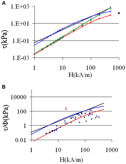
Figure 1. (A) Theoretical yield stress vs. the field acting on the particles. Red squares: calculated from FEMM; green triangles calculated from multipolar forces; black solid line: Equation (6); blue crosses: Equation (7) with Fr calculated with FEM. The red dot corresponds to the saturation of the magnetization. (B) Comparison theory-experiment for τy/Φ. Blue diamonds: experimental points taken from Table S1. Red line, FEM result; black line, Equation (6); Blue line, Equation (7); Purple star, jamming transition.
Rupture at Zero Strain
Here we suppose that the particles are packed in some disordered way, and that the solid phase will yield suddenly when the shear stress is high enough to separate the particles on a given “cutting” plane which, in a simple shear, is perpendicular to the velocity gradient. This kind of model is used to predict the yield stress of suspensions of particles aggregated in the presence of Van der Waals forces (Scales et al., 1998). The only difference in our case is that the interparticle force is proportional to (Hcosθ)2 instead of being independent of θ. Otherwise the interparticle distances are supposed to be distributed isotropically, which is mainly true at a high-volume fraction. Following the same steps as in Scales et al. (1998) we obtain:
The factor 3/20 comes from the cos2θ instead of 1/4 for an isotropic force. The function K(Φ) is the coordination number taken from Suzuki et al. (1981) and ε0 is the minimum gap between two particles.
Comparison of the Different Models
The predictions of the different models are reported in Figure 1A. Firstly if we compare, in the affine model, the predictions related to the 3 different approximations of forces: Equations (1, 3, 4),we recover the fact that the multipolar model gives a rather good prediction for low fields but, due to the linear magnetization hypothesis, highly overestimates the yield stress at high fields. The analytic expression overestimates the yield stress given by FEM, by about one order of a magnitude. Lastly, the model of rupture at zero strain (Equation 7), is calculated with the force Fr obtained by FEM for ε = 0.002, which is a reasonable value considering a coating layer of 2 nm and a radius of 1 μm. The corresponding prediction is well-above the FEM prediction and is, by chance, quite close to that of the analytical model. It should also be noted that the fit of the yield stress by a power law:τy = K.Hn provides a good fit with n = 1.94 (R2 = 0.9997) only for H ≤ 50 kA/m (Figure S3) which is three times smaller than the field used for the transition from H2 to H3/2 (Hc = 151 kA/m) in Fang et al. (2009). It is also worth noting that the radial force, at contact between two particles, increases steadily in the range of ε = 0–0.01(cf Table S2), which may explain, at least in the rupture model, the decrease of the yield stress in the presence of a coating layer (Cvek et al., 2018). This comparison of the models was done for two spheres in a given field, which we consider as the average field, in order to compare with the experiments in the next section. Some numerical results for the yield stress of a set of particles can be obtained with a good precision in a multipolar approach, even for high permeability, but for particles distributed on a periodic network (Clercx and Bossis, 1993) with an affine deformation. In this case all the particles are separated by the same gap, which is an unphysical and unstable structure. It is also possible to use a double chain structure so that it can deform and still keep contacts and stability, but it underestimates the yield stress (López-López et al., 2012) and also can't be used in numerical simulations. In fact, almost all numerical simulations of MR suspensions use the dipolar approximation, which largely underestimates the magnetic force (Clercx and Bossis, 1993). We have found one paper (Lacis and Gosko, 2009) using an expression similar to Equation (1), with some tables derived from FEM simulations for two particles and another based on FEM simulations between several particles in a single chain (Kang et al., 2012). A simulation method, called smooth particle dynamics (Hashemi et al., 2016, 2018), can also be used to solve the magnetostatics equation between several particles, but is restricted to a few particles with a rather small (<10) susceptibility. As discussed in the next section, the use of a magnetic force derived from FEM, calculated with a very fine mesh for two particles, is quite realistic and certainly much more efficient in terms of computing time.
Comparison With Experiments
Comparing these predictions with experimental data is not so simple as, very often, the knowledge of the experimental conditions is incomplete. We have selected data concerning carbonyl iron particles (CI) whose magnetization curve of the powder is rather well-established with a saturation magnetization of 200 emu/g. Usually the experiments are made in plate-plate geometry, with the field perpendicular to the plate. In order to compare with the theory, we must first consider that the field inside the suspension is H = H0/μ(H), where H0 is the external field measured in the absence of suspension and μ(H) the permeability of the suspension. We have deduced the magnetization curve of CI particles from a measurement of M(H) at a volume fraction: Φ = 64%. This magnetization curve of CI particles is well-fitted in the range 0–400 kA/m by a Langevin curve:M1(H) = (coth(c.H)-1/c.H)Msr with c = 0.014 and Msr = 1750 kA/m. This last value is slightly higher than the saturation magnetization of CI (Ms ≈ 1600 kA/m) due to a shift of the fit for H>400 kA/m. The magnetization at any volume fraction of the suspension is obtained by replacing Msr by Msr.Φ and we have checked that it works well-even at low Φ, for instance for Φ = 0.2 and Φ = 0.32 BASF. The permeability for any given volume fraction is then: μ(H) = 1+M1(H).Φ/H The second point we need to take into account is that, in the plate-plate configuration, the yield stress provided by the software is overestimated by a factor of 4/3 (Bossis et al., 2002; Laun et al., 2010). The data collected in different publications (Kordonski and Golini, 1999; Chin et al., 2001; Lim et al., 2004; Jang et al., 2005; Cheng et al., 2009; Ierardi and Bombard, 2009; Laun et al., 2010; Kim et al., 2012; Bombard et al., 2015; Esmaeilnezhad et al., 2017; Dong et al., 2018; Plachy et al., 2018) are reported in Table S1 and plotted in Figure 1B (blue diamonds). There is a considerable scatter of the data, but it appears clearly that the affine model with the calculation of forces through FEM (red curve), provides the best prediction compared to both Equation (6) and Equation (7). Now, we draw the attention on the single point (purple cross) above all the curves in Figure 1B which is the result of a jamming transition.
Jamming Transition at High Volume Fraction
Jamming transition, also known as discontinuous shear thickening (DST), was observed in highly concentrated suspensions of solid non-Brownian particles like ceramics (Bergström, 1998), cornstarch (Fall et al., 2008, 2015) and also in model suspensions made of PMMA (Pan et al., 2015) or silica particles (Lootens et al., 2003) and calcium carbonate (Bossis et al., 2017). In the two last systems, superplasticizer molecules, common in the cement industry, were used as surfactants. We have recently found that by using, for instance, a polyoxyethylene polyphosphonate (Bossis et al., 2017), we can reach volume fractions of CI particles in water larger than 60%, still keeping a low yield stress and a viscosity of 1-2Pa.s. Now the rheogram at the zero field presents a singularity at a critical stress, where the shear rate abruptly decreases during a ramp of stress (Figure 2A). This DST phenomenon is due to the transition of a lubricated regime to a frictional one (Mari et al., 2014; Wyart and Cates, 2014). Above this point the shear rate fluctuates around some low values. We also see on this graph that, by increasing the volume fraction, the critical stress increases and the critical shear rate decreases. These critical values are obtained at zero magnetic field, but when the field is increased for a given volume fraction, the critical shear rate will continuously decrease to zero in a field range typically of 0–20 kA/m (Bossis et al., 2016). If instead of applying a ramp of stress we apply a ramp of shear rate, at the critical point we then obtain a jump of stress to very high values which overcomes the range of conventional rheometers. This is the purple point in Figure 1B. which was obtained in the presence of a field of 19.2 kA/m. The corresponding evolution of stress is plotted in Figure 2B vs. the strain. It was obtained in a cylindrical Couette flow with a vane tool and a homemade rheometer to be able to measure high torques (Bossis et al., 2016). The shear rate was increased from 0 to 1.6 s−1 in 2 s then kept constant for 25 s. The stress does not grow until the strain reaches a value around one and then increases up to 150 kPa where it remains constant afterwards. The interesting point is that this transition from a normal regime to this frictional regime can be controlled by the application of a low magnetic field (a few kA/m), thus opening the door for new applications of MR fluids. It is worth noting that a very high value of yield stress in a MR fluid was previously attained in another way, which also mobilizes the friction between particles, but with the help of a lateral pressure obtained by the compression of the suspension of the initial volume fraction Φ = 45% by sliding wedges (Tao, 2001). As reported in numerous previous works, [for instance (Ashtiani et al., 2015; Cvek et al., 2018)] the additives are used to stabilize the particles against corrosion and sedimentation; they can either increase the yield stress through a better compaction of the local structure [term K[Φ] in Equation (7)], or decrease it if the coating layer is too thick [term Fr(ε0) in Equation (7)]. In our case it plays a key role due its expulsion from the surface, which provokes the jamming transition.

Figure 2. (A) Rheogram of carbonyl iron suspensions with 0.2% of superplasticizer at high-volume fraction (blue:60%, orange 61%, black 62%,green 63%). (B) Stress vs. strain in cylindrical Couette geometry with vane tool, Φ = 0.61;H0 = 19.2 kA/m, The vertical red line corresponds to a time of 2 s where the shear rate has reached its final value of 1.6 s−1.
Conclusion
In this paper we have briefly reviewed the models of yield stress under the hypothesis of affine displacement of the particles and have also proposed a new approach based on a rupture model. It appears that the affine motion, with a calculation of the forces through FEM simulation, provides the best agreement with the experimental data of τy/Φ, collected for carbonyl iron suspensions. The commonly used Equation (6) strongly overestimates the experimental results but its prediction of a regime τy∝ H3/2 is verified between ~50 and 200 kPa. No model is able to predict the high value of stress at low field obtained in suspensions of very high-volume fractions: Φ >0.6. In this case, it is the abrupt transition toward a frictional regime after expulsion of a superplasticizer layer, which leads to very high values of stress. This transition is obtained either above a critical magnetic field or above a critical shear rate, which opens up new perspectives for applications that require a strong response with a small field.
Author Contributions
GB, OV, YG, and AC contributed conception and design of the study. GB wrote the first draft of the paper. OV found and organized the references and the figures. YG filled the database of the previous works on the subject and AC contributed to the theoretical part. All authors contributed to manuscript revision, read and approved the submitted version.
Funding
Center National d'Etudes Spatiales (CNES, the French Space Agency).
Conflict of Interest Statement
The authors declare that the research was conducted in the absence of any commercial or financial relationships that could be construed as a potential conflict of interest.
Acknowledgments
This work was supported by the Center National d'Etudes Spatiales CNES. We also thank the mechanical workshop of our institute for fabricating part of our home made rheometer.
Supplementary Material
The Supplementary Material for this article can be found online at: https://www.frontiersin.org/articles/10.3389/fmats.2019.00004/full#supplementary-material
Figure S1. Schematic of the notations for two particles in a magnetic field.
Figure S2. Force vs. magnetic field for a separation ε = 0.01; black line: analytic expression: Equation (3); green triangles: multipolar approach: Equation (1); red triangles: FEM, Equation (4).
Figure S3. Power law fit of the FEM result for the normalized yield stress τy/Φ. Red solid line:power law with n = 1.94; blue solid line: power law with n = 3/2;red crosses: FEM result; black solid line: Equation (6).
Table S1. Corrected experimental yield stress normalized by the volume fraction (column E) in kPa vs. the Maxwell field in the suspension (column H) in kA/m.
Table S2. Coefficients of the force in Equation (1) for differents values of α = μp/μf vs. the gap ε.
Table S3. Values of the force obtained with the free software FEMM for different fields and separations between two spheres. The parameters for the fit vs. the normalized separation, ξ, (<0.2) are given for each field.
References
Ashtiani, M., Hashemabadi, S. H., and Ghaffari, A. (2015). A review on the magnetorheological fluid preparation and stabilization. J. Magn. Magn. Mater. 374, 716–730. doi: 10.1016/j.jmmm.2014.09.020
Bergström, L. (1998). Shear thinning and shear thickening of concentrated ceramic suspensions. Colloids Surf. A 133, 151–155. doi: 10.1016/S0927-7757(97)00133-7
Bombard, A. J., Gonçalves, F. R., and de Vicente, J. (2015). Magnetorheology of carbonyl iron dispersions in 1-Alkyl-3-methylimidazolium ionic liquids. Ind. Eng. Chem. Res. 54, 9956–9963. doi: 10.1021/acs.iecr.5b02824
Bossis, G., Boustingorry, P., Grasselli, Y., Meunier, A., Morini, R., Zubarev, A., et al. (2017). Discontinuous shear thickening in the presence of polymers adsorbed on the surface of calcium carbonate particles. Rheol. Acta 56, 415–430. doi: 10.1007/s00397-017-1005-4
Bossis, G., Grasselli, Y., Meunier, A., and Volkova, O. (2016). Outstanding magnetorheological effect based on discontinuous shear thickening in the presence of a superplastifier molecule. Appl. Phys. Lett. 109:111902. doi: 10.1063/1.4962467
Bossis, G., Volkova, O., Lacis, S., and Meunier, A. (2002). “Magnetorheology: fluids, structures and rheology,” in Ferrofluids, Part of Lecture Notes in Physics, Vol. 594 (Springer), 202–230.
Cheng, H. B., Wang, J. M., Zhang, Q. J., and Wereley, N. M. (2009). Preparation of composite magnetic particles and aqueous magnetorheological fluids. Smart Mater Struct. 18:085009. doi: 10.1088/0964-1726/18/8/085009
Chin, B. D., Park, J. H., Kwon, M. H., and Park, O. O. (2001). Rheological properties and dispersion stability of magnetorheological (MR) suspensions. Rheologica Acta 40, 211–219. doi: 10.1007/s003970000150
Clercx, H. J. H., and Bossis, G. (1993). Electrostatic interactions in slabs of polarizable particles. J. Chem. Phys. 98, 8284–8293. doi: 10.1063/1.464534
Cvek, M., Mrlík, M., Moucka, R., and Sedlacik, M. (2018). A systematical study of the overall influence of carbon allotrope additives on performance, stability and redispersibility of magnetorheological fluids. Colloids Surf. A 543, 83–92. doi: 10.1016/j.colsurfa.2018.01.046
De Vicente, J., Bossis, G., Lacis, S., and Guyot, M. (2002). Permeability measurements in cobalt ferrite and carbonyl iron powders and suspensions. J. Magn. Magn. Mater. 251, 100–108. doi: 10.1016/S0304-8853(02)00484-5
Dong, Y. Z., Piao, S. H., Zhang, K., and Choi, H. J. (2018). Effect of CoFe2O4 nanoparticles on a carbonyl iron based magnetorheological suspension. Colloids Surf. A 537, 102–108. doi: 10.1016/j.colsurfa.2017.10.017
Esmaeilnezhad, E., Jin Choi, H., Schaffie, M., Gholizadeh, M., Ranjbar, M., and Hyuk Kwon, S. (2017). Rheological analysis of magnetite added carbonyl iron based magnetorheological fluid. J. Magnetism Magnetic Mater. 444, 161–167. doi: 10.1016/j.jmmm.2017.08.023
Fall, A., Bertrand, F., Hautemayou, D., Mézière, C., Moucheront, P., Lemaitre, A., et al. (2015). Macroscopic discontinuous shear thickening versus local shear jamming in cornstarch. Phys. Rev. Lett. 114:098301. doi: 10.1103/PhysRevLett.114.098301
Fall, A., Huang, N., Bertrand, F., Ovarlez, G., and Bonn, D. (2008). Shear thickening of cornstarch suspensions as a reentrant jamming transition. Phys. Rev. Lett. 100:018301. doi: 10.1103/PhysRevLett.100.018301
Fang, F. F., Choi, H. J., and Jhon, M. S. (2009). Magnetorheology of soft magnetic carbonyl iron suspension with single-walled carbon nanotube additive and its yield stress scaling function. Colloids Surf. A 351, 46–51. doi: 10.1016/j.colsurfa.2009.09.032
Ginder, J. M., Davis, L. C., and Elie, L. D. (1996). Rheology of magnetorheological fluids: models and measurements. Int. J. Mod. Phys. B 10, 3293–3303. doi: 10.1142/S0217979296001744
Hashemi, M. R., Manzari, M. T., and Fatehi, R. (2016). A SPH solver for simulating paramagnetic solid fluid interaction in the presence of an external magnetic field. Appl. Math. Model. 40, 4341–4369. doi: 10.1016/j.apm.2015.11.020
Hashemi, M. R., Manzari, M. T., and Fatehi, R. (2018). Direct numerical simulation of magnetic particles suspended in a Newtonian fluid exhibiting finite inertia under SAOS. J. Non-Newtonian Fluid Mech. 256, 8–22. doi: 10.1016/j.jnnfm.2018.03.004
Ierardi, R. F., and Bombard, A. J. (2009). Off-state viscosity and yield stress optimization of magneto-rheological fluids: a mixture design of experiments approach. J. Phys. Conf. Series 149:012037. doi: 10.1088/1742-6596/149/1/012037
Jang, I. B., Kim, H. B., Lee, J. Y., You, J. L., Choi, H. J., and Jhon, M. S. (2005). Role of organic coating on carbonyl iron suspended particles in magnetorheological fluids. J. Appl. Phys. 97:10Q912. doi: 10.1063/1.1853835
Kang, T. G., Hulsen, M. A., and den Toonder, J. M. (2012). Dynamics of magnetic chains in a shear flow under the influence of a uniform magnetic field. Phys. Fluids 24:042001. doi: 10.1063/1.4704822
Kim, M. S., Liu, Y. D., Park, B. J., You, C.-Y., and Choi, H. J. (2012). Carbonyl iron particles dispersed in a polymer solution and their rheological characteristics under applied magnetic field. J. Indus. Eng. Chem. 18, 664–667. doi: 10.1016/j.jiec.2011.11.062
Klingenberg, D. J., and Zukoski, C. F. (1990). Studies on the steady-shear behavior of electrorheological suspensions. Langmuir 6, 15–24. doi: 10.1021/la00091a003
Kordonski, W. I., and Golini, D. (1999). Fundamentals of Magnetorheological fluid utilization in high precision finishing. J. Intell. Mater. Syst. Struct. 10, 683–689. doi: 10.1106/011M-CJ25-64QC-F3A6
Lacis, S., and Gosko, D. (2009). Direct numerical simulation of MR suspension: the role of viscous and magnetic interactions between particles. J. Phys. 149:012066. doi: 10.1088/1742-6596/149/1/012066
Laun, H. M., Gabriel, C., and Kieburg, C. (2010). Twin gap magnetorheometer using ferromagnetic steel plates—performance and validation. J. Rheol. 54, 327–354. doi: 10.1122/1.3302804
Lim, S. T., Cho, M. S., Jang, I. B., and Choi, H. J. (2004). Magnetorheological characterization of carbonyl iron based suspension stabilized by fumed silica. J. Magnetism Magnetic Mater. 282, 170–173. doi: 10.1016/j.jmmm.2004.04.040
Lootens, D., Van Damme, H., and Hébraud, P. (2003). Giant stress fluctuations at the jamming transition. Phys. Rev. Lett. 90:178301. doi: 10.1103/PhysRevLett.90.178301
López-López, M. T., Kuzhir, P., Caballero-Hernandez, J., Rodríguez-Arco, L., Durán, J. D., and Bossis, G. (2012). Yield stress in magnetorheological suspensions near the limit of maximum-packing fraction. J. Rheol. 56:1209. doi: 10.1122/1.4731659
Mari, R., Seto, R., Morris, J. F., and Denn, M. M. (2014). Shear thickening, frictionless and frictional rheologies in non-Brownian suspensions. J. Rheol. 58, 1693–1724. doi: 10.1122/1.4890747
Pan, Z., de Cagny, H., Weber, B., and Bonn, D. (2015). S-shaped flow curves of shear thickening suspensions: Direct observation of frictional rheology. Phys. Rev. E 92:032202. doi: 10.1103/PhysRevE.92.032202
Plachy, T., Kutalkova, E., Sedlacik, M., Vesel, A., Masar, M., and Kuritka, I. (2018). Impact of corrosion process of carbonyl iron particles on magnetorheological behavior of their suspensions. J. Indus. Eng. Chem. 66, 362–369. doi: 10.1016/j.jiec.2018.06.002
Scales, P. J., Johnson, S. B., Healy, T. W., and Kapur, P. C. (1998). Shear yield stress of partially flocculated colloidal suspensions. AIChE J. 44, 538–544. doi: 10.1002/aic.690440305
Suzuki, M., Makino, K., Yamada, M., and Linoya, K. (1981). A study on the coordination number in a system of randomly packed uniform sized spheres. Int. Chem. Eng. 21, 482–488.
Tao, R. (2001). Super-strong magnetorheological fluids. J. Phys. 13, R979–R99. doi: 10.1088/0953-8984/13/50/202
Keywords: carbonyl iron, yield stress, discontinuous shear thickening, jamming, magnetorheology
Citation: Bossis G, Volkova O, Grasselli Y and Ciffreo A (2019) The Role of Volume Fraction and Additives on the Rheology of Suspensions of Micron Sized Iron Particles. Front. Mater. 6:4. doi: 10.3389/fmats.2019.00004
Received: 29 October 2018; Accepted: 10 January 2019;
Published: 08 February 2019.
Edited by:
Seung-Bok Choi, Inha University, South KoreaReviewed by:
Xufeng Dong, Dalian University of Technology (DUT), ChinaEvguenia Korobko, A.V. Luikov Heat and Mass Transfer Institute (NASB), Belarus
Copyright © 2019 Bossis, Volkova, Grasselli and Ciffreo. This is an open-access article distributed under the terms of the Creative Commons Attribution License (CC BY). The use, distribution or reproduction in other forums is permitted, provided the original author(s) and the copyright owner(s) are credited and that the original publication in this journal is cited, in accordance with accepted academic practice. No use, distribution or reproduction is permitted which does not comply with these terms.
*Correspondence: Georges Bossis, bossis@unice.fr