Between Science and Art: Thin Sound Absorbers Inspired by Slavic Ornaments
 Anastasiia O. Krushynska
- Faculty of Science and Engineering, ENTEG-Engineering and Technology Institute Groningen, University of Groningen, Groningen, Netherlands
Acoustic metamaterials have opened fascinating opportunities for manipulation of low-frequency sound and development of compact structures with broadband acoustic performance for noise mitigation applications, room and architectural acoustics. So far, several mechanisms have been studied to achieve perfect sound absorption at subwavelength frequencies, when structural dimensions are much smaller than the wavelength of incident waves. Here, we analyze two alternative approaches based on the use of interacting and coupled resonators in absorbing panels with the aim to reduce the panel thickness. We numerically demonstrate that proper designs of interacting resonators allow extending a single-peak absorption to broadband frequencies, while the use of coupled resonators enables broadband absorption at several frequency ranges. The proposed configurations are inspired by ancient Slavic folk patterns with delicate ligature, multi-layered structure, and concealed meaning. Our results open new possibilities for creating acoustic metamaterials with added art effects, which individualize occupied space and make absorbing panels more appealing for various applications.
1. Introduction
Manipulation of low-frequency sound is a challenge due to the limited acoustic performance of conventional materials (Allard and Atalla, 2009). Recently developed acoustic metamaterials (Liu et al., 2000; Deymier, 2013; Brunet et al., 2015) and metasurfaces (Holloway et al., 2012; Liang and Li, 2012) have enabled advanced control of sound waves due to unusual functionalities, including negative refraction (Fang et al., 2006; Kaina et al., 2015; Krushynska et al., 2017), sound focusing (Guenneau et al., 2007; Li et al., 2009), acoustic cloaking (Li and Pendry, 2008; Kan et al., 2016), and one-way propagation (Liang et al., 2010; Fleury et al., 2014) (see also the excellent reviews of Craster and Guenneau, 2012; Cummer et al., 2016; Liang et al., 2018; Wu et al., 2018 for additional references). These fascinating properties have opened the way to the development of compact sound absorbing materials. For example, membrane-type (Yang et al., 2008, 2015; Park et al., 2011; Mei et al., 2012; Lu et al., 2016; Gao et al., 2017) or scape-coiling (Liang and Li, 2012; Li et al., 2012, 2013, 2014, 2015; Xie et al., 2013, 2014; Molerón et al., 2016; Krushynska et al., 2018) metamaterials are capable of totally absorbing sound at frequencies, when the corresponding wavelength is up to two orders of magnitude larger than their thickness. Rigidly-backed structures with Helmholtz resonators (HRs) (Jiménez et al., 2016, 2017a) also act as perfect absorbers, if the critical coupling conditions are satisfied (Theocharis et al., 2014; Merkel et al., 2015; Groby et al., 2016). However, the resonant nature of the dispersion manipulation mechanisms results in narrowband performance that substantially limits application possibilities of meta-structures.
A common approach to broaden the bandwidth is the use of multiple detuned resonating units with absorption peaks at different frequencies. These can be optimally designed panels with graded sets of quarter-wavelength resonators (Jiang et al., 2014; Groby et al., 2016), series of detuned HRs (Groby et al., 2015; Jiménez et al., 2016, 2017b), space-coiled channels (Zhang and Hu, 2016; Tang et al., 2017; Jia et al., 2018) or poroelastic plates in rigidly-backed waveguides (Romero-García et al., 2016). Other solutions include membranes (Mei et al., 2012) or plate-type (Ma et al., 2017, 2018) structures decorated by multiple masses. The use of optimized coiled-up Fabry-Perot channels even enables to achieve a minimum sample thickness imposed by causality (Yang et al., 2017).
This work investigates two alternative approaches to extend the absorption performance of acoustic metamaterials with internal HRs under restriction on structural thickness. The first approach relies on synergetic interactions of detuned HRs resulting in merging of isolated absorption peaks and, thus, broadband absorption. An important feature is that the HRs are equidistant from the sound source, in contrast to widely analyzed “in-series” arrangement (Jiménez et al., 2016, 2017a,b,c; Romero-García et al., 2016), that largely reduces the system thickness. To decrease the lateral dimensions, we adopt the space-coiling mechanism for the HR cavities. The second approach introduces the concept of coupled HRs when an HR cavity is separated into two (or several) parts joint by the supplementary neck(s). We show that a coupled resonator preserves the first-order absorption peak originating from the initial configuration and exhibits additional absorption peak(s) at subwavelength frequencies. This characteristic enables broadband sound absorption at several frequency ranges, without introducing additional HRs or a noticeable increase in the system dimensions. The developed approaches are illustrated by the examples of acoustic absorbers inspired by ancient Slavic ornaments.
The choice of ornamental designs is not by chance. Common applications of sound absorbers are in the areas of architectural acoustics, room acoustics and noise insulation, including sound mitigation in public buildings (hotels, offices, schools, stations, shopping malls, etc.), target acoustics of theaters, attenuation of air- or structure-borne noise, etc. Given the advanced functionalities of acoustic metamaterials, one may think of fascinating effects of variable audible space, in contrast to its fixed physical dimensions, that is of importance for modern cinemas and concert halls. These applications obviously imply high visibility of meta-structures suggesting that they should not only be functional and optimized but also give meaning to the occupied space. Moreover, since even the thinnest absorbers reduce available space, they can be designed in a creative way, playing the role of artwork, in addition to tailored audible performance. This can be achieved by incorporating ornamental designs of acoustic metamaterials, i.e., balancing the relationship between voids and solids, with the aim to improve visual experience and personalize the environment targeted at a specific audience.
The paper is organized as follows. After the introduction, section 2 provides basic information about the peculiarities of Slavic ornaments. In section 3, we introduce a general model of the proposed sound absorbers and describe the numerical approach to analyze their absorption capability. Section 4 discusses the properties of absorbers with folded HRs sharing the spatial location. Section 5 presents the concept of coupled resonators and the design of an acoustic absorber with broadband quasi-perfect (≥95%) sound absorption at low frequencies. Finally, section 6 summarizes the main findings of the paper and illustrates how the proposed designs can be integrated in a room interior.
2. Slavic Ornaments
Slavic ornaments are decorative elements in architecture, weaving, and fancywork of Slavs native to Central, Eastern, and Southeastern Europe. They resemble holographic pictures that should be viewed with defocused eyes (to create a stereoscopic 3D effect) by switching attention between dark and light patterns, which have a different meaning. The interpretation of patterns varies depending on their location at a piece of clothing or an object. The basic constituent elements range from simple geometric forms to complex images of plants, animals, geometric forms, etc.
Antique ornaments are characterized by isometric areas of a background and a pattern so that intervals between the patterns also have a symbolic meaning (Kachaeva, 2008). This resulted that ornaments were typically entitled according to the shape of unfilled area, rather than to a pattern itself. Some traditional symbols of Slavic patterns are shown in Figure 1A.
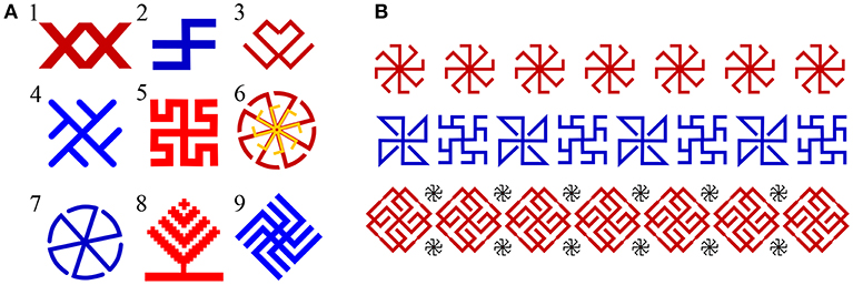
Figure 1. (A) Some symbols in geometric Slavic ornaments and their Slavic names (with English translations, if possible): 1—“vodyanoj” (the water sprite); 2—“slavez”; 3—“kryuchki” (hooks); 4—“kolard”; 5—“bogovnik”; 6—“svetoch” (cresset); 7—“grozovik” (the spirit of thunderstorm); 8—“derevo” (tree); 9—“vepr' nebesnyj” (the sky wild boar). (B) Top: a row of the symbols “kolyadnik” (a kind of Christmas carol); middle: alternations of the symbols “solon'” and “the fern flower”; bottom: rows of the symbols “skarozhych” and “kolyadnik”.
The weaving technique of symbolic ornaments governs not only the strict geometry and proportions of patterns, but also their high density. In addition, it influences the sequence of ornamental patterns based on the symmetry of different orders (Nekrasova, 1983). Strong traditions of periodic repetitions of symbols resulted that separate symbols, unlike letters, have no meaning, but altogether, in combinations with other symbols, translate a comprehensive mythological figure or character (Figure 1B).
Surprisingly, Slavic ornamental patterns are not unique, and have close counterparts around the world. Except some differences in graphics and colors, similar meaning, rhythm, and temper are recognizable in Scandinavian, Arabic, Brazilian, and other ornaments (Nekrasova, 1983; Kachaeva, 2008). Rich history of Slavic ornaments together with examples of multiple patterns from different centuries and comprehensive interpretation of their meaning can be found elsewhere (see e.g., the excellent surveys of Nekrasova, 1983; Kachaeva, 2008, and the references therein).
The preservation of the ancient art of folk ornaments is a vital problem of significant cultural and societal importance. One of the possible solutions can be the use of ornamental patterns in the design of functional acoustic devices proposed in sections 4 and 5.
3. Models and Methods
In this work, we numerically analyze the absorption of air-borne sound in acoustic metamaterials with Helmholtz resonators (HRs) using the concepts of slow sound and critical coupling (Theocharis et al., 2014; Groby et al., 2015; Jiménez et al., 2017a). The designed systems are thin rigidly-backed panels with periodic sets of perforated cylindrical holes of length L loaded by N resonators and arranged in a rectangular lattice with pitches Lx, Ly in the Oxy plane (Figure 2A). An HR is composed of a cylindrical neck of radius and length and a cylindrical cavity of radius and length , where the superscript k indicates the HR number (Figure 2B). In the analyzed frequency ranges, the wavelength of sound waves is larger than the HR dimensions, and thus, the holes loaded by the HRs (Figure 2C) act as asymmetric Fabry-Perót cavities with N point-like resonant scatterers and the rigid backing, playing the role of a mirror (Romero-García et al., 2016;Jiménez et al., 2017a).
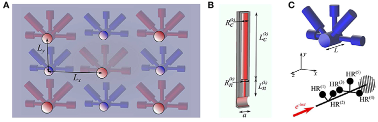
Figure 2. (A) Sketch of a rigidly-backed transparent panel with cylindrical perforated cavities arranged in a rectangular lattice and loaded by five colored HRs. (B) The dimensions of a Helmholtz resonator. (C) Top: the geometry of a cavity loaded by five HRs; bottom: schematic diagram of the corresponding 1D analog with the red arrow indicating the direction of incident sound.
As the perforations are periodic, the panel dynamics is analyzed by considering an elementary building block. Periodic boundary conditions are applied at the lateral boundaries of the block, normal to the x and y axes, which are reduced to symmetric boundary conditions for normally incident waves. The system absorption α = 1 − |R|2 with the complex reflection coefficient R evaluated numerically. A finite-element model is developed by using the Pressure Acoustic module of the COMSOL Multiphysics v.5.2 (the Comsol files are available in Krushynska, 2019). The model includes the air confined in the panel and surrounding free air with mass density ρair = 1.21 kg/m3, sound speed c0 = 343 m/s and dynamic viscosity η = 1.8 × 10⁻⁵ Pa·s at T = 293 K. For the air inside the HRs and the Fabry-Perót cavities, the visco-thermal losses are taken into account by means of effective complex-valued bulk modulus Keff and mass density ρeff (Groby et al., 2015):
Here P0 = 1 atm is the atmospheric pressure; γ = 1.4 and Pr are the specific heat ratio and the Prandtl number; J0 and J1 are the standard Bessel's functions of the first kind; r is the radius of a cylinder. Harmonic plane waves of a unit amplitude and frequency ω are normally incident on the panel surface along the negative direction of the z axis (the red arrow in Figure 2C). Due to a large impedance mismatch, the sound hard boundary conditions are imposed at the interfaces of the air and solid elements. The reflection coefficient is calculated by evaluating the acoustic pressure p1 and p2 at two acquisition points:
where H12 = p1/p2, d is the distance between the points, k = ω/c0 is the wavenumber. More details on the numerical implementation can be found in Appendix.
4. Folded Interacting Resonators for Broadband Absorption
In this section, we design and analyze acoustic absorbers with HRs sharing spatial location, i.e., having identical z coordinates. We demonstrate that such an arrangement allows not only reducing the thickness of a panel, but also improves its absorption performance. We first consider a panel with six detuned HRs arranged “in-series” on a tube of radius Rt = 7 mm, with the center-to-center distance a = L/6 = 15 mm. The radii of the neck Rn = 2.5 mm and the HR cavity Rr = 5 mm are identical for all the HRs. The lengths of the HR necks are mm, mm, mm, mm, mm, and mm. For the identical total length of every HR equal to 11.92 cm, the resonator eigenfrequencies are kHz, Hz, Hz, Hz, Hz, and Hz.
We start from the evaluation of wave dispersion by applying the Floquet-Bloch conditions at the tube ends (Krushynska et al., 2018), imitating an infinite sequence of the HRs, and by neglecting any losses in the system. Figure 3A shows the corresponding dispersion relation with the band gaps shaded in gray. The lowest pass band is strongly dispersive with the phase velocity ω/k lower than c0 (cf. the pass band c0 for a sound wave in free air shown by the dashed red line), indicating the activation of slow sound conditions at these frequencies (Theocharis et al., 2014; Jiménez et al., 2017a). At the cut-off frequency of the first pass band (L/λ = Lf/c0 = 0.105), the phase velocity is zero, and the corresponding mode shape has maximum acoustic pressure in the cavities of the fifth and sixth HRs (with the longest necks) and close-to-zero pressure level in the other four HRs. The simultaneous excitation of the two HRs explains a lower cut-off frequency, 402 Hz, as compared to individual eigenfrequencies of the excited HRs. Above the cut-off, one observes a small band gap with an upper bound formed by an almost flat band, which, in turn, is a low bound of an adjacent band gap. Altogether, there are five small band gaps separated by (almost) flat bands. The separating pass bands correspond to modes localized in the HRs and have similar vibration patterns: two HRs with strong out-of-phase pressure levels and one weakly excited HR (e.g., Figure 3B, on the left). The simultaneous activation of several HRs explains lower frequencies of the localized modes relative to . The fifth flat band forms a lower bound of a large band gap centered around L/λ = 0.2. This and the next large band gaps are separated by a mode with the pressure distribution shown in Figure 3B on the right.
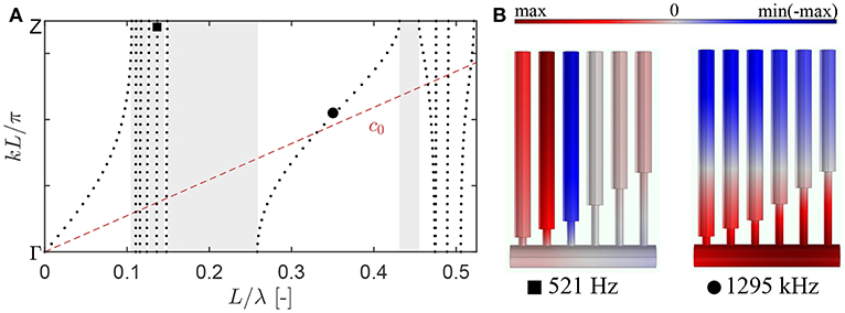
Figure 3. (A) The dispersion relation for a periodic arrangement of the six detuned HRs on a tube. The shaded regions indicate band gaps with inhibited wave propagation. The dashed line c0 describes a propagating band of sound waves in free air. (B) The pressure distribution at frequencies indicated in (A).
The discussed dispersion properties reveal that the panel can manipulate sound waves at subwavelength frequencies since the characteristic system size L is smaller than the wavelength of an incident sound wave λ.
Next, we analyze the sound absorption for a finite-size tube with the six HRs. If the HRs with the longer necks are placed close to the air domain (Figure 4A), the absorption coefficient of the panel has three non-zero peaks below 1.5 kHz (L/λ < 0.5). At the first peak, 328 Hz (α = 0.78), the HRs and the cavity act as rigid scatterers for an incident wave and are characterized by a uniform pressure distribution. At the second peak, 407 Hz, only the HR with the longest neck (the sixth HR) is activated. It has the lowest eigenfrequency , and thus, the resonant frequencies of the other HRs fall in the band gap. In other words, at frequencies above , sound waves are strongly reflected, and only a small amount of energy propagates further in the cavity, which is insufficient to activate the other HRs. Since the geometry of the excited HR is not optimized to critically couple the system with the exterior medium, it results in a low absorption α = 0.08. Instead, if sound waves incident on a panel with on opposite order of the HRs (Figure 4B), the activation of each HRs becomes possible, and the absorption coefficient has seven peaks below the second large band gap. In the absence of losses, the peaks of Re(R) (the dotted line) match the frequencies of the localized modes in the dispersion relation (Figure 3A). In the lossy case (the solid lines), the reflection and absorption peaks are shifted to slightly lower frequencies (Molerón et al., 2016). Note that the first absorption peak occurs at a similar frequency, 316 Hz with α = 0.58, as in Figure 4A, and has the same pressure distribution.
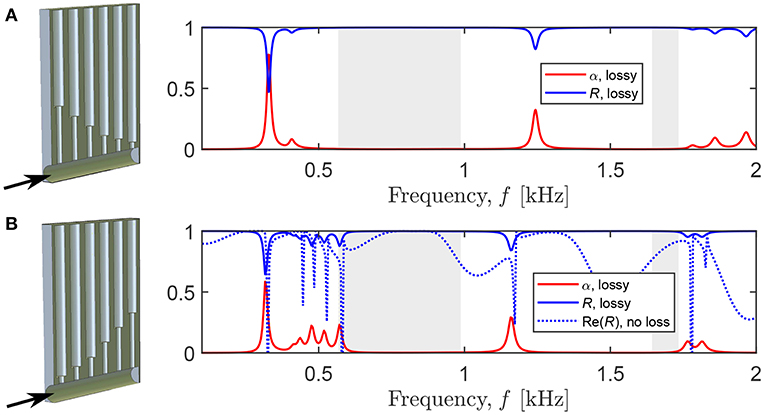
Figure 4. The reflection (blue) and absorption (red) coefficients for the panels with periodically arranged rigidly-backed cavities loaded by six detuned HRs. The black arrow indicates the direction of incident sound. Shaded regions indicate the band gaps evaluated by the dispersion analysis (only the two wide band gaps are presented). The arrangement of the HRs with gradually (A) decreasing and (B) increasing length of a neck.
The obtained results show that the absorption of a panel with detuned HRs strongly depends on the arrangement of the HRs—the property first discussed for the transmission problem in Jiménez et al. (2017b). One can maximize the panel absorption by optimizing the HR geometries in order to satisfy the critical coupling conditions (Jiménez et al., 2017a,b).
Alternatively, the absorption can be increased by varying the positions of the HRs along the cavity. To this end, we consider the system with the gradually increasing HR necks toward the closed end of the tube (Figure 4B). We fold the HR cavities by curving the parts of length 5.42 cm from the top and rotating them 90° to the remaining parts (Figure 5A). This transformation should preserve the HR eigenfrequencies and the absorption coefficient of the panel as proven experimentally elsewhere (Jiménez et al., 2017a; Yang et al., 2017). The simulations show that it is indeed the case, except for the first absorption peak that is reduced by 10%. This decrease can be explained by the use of Equations (1) and (2), which are, strictly speaking, not applicable for non-uniform cross-sections of the HR cavities. However, the insertion of the losses by means of the effective parameters (1) and (2) leads to a computationally cheaper problem as compared to the direct incorporation of thermal and viscous boundary layers into a finite-element model (Krushynska et al., 2018). Since the inaccuracy concerns only the first absorption peak, and the goal of this work is not the demonstration of some quantitative results, but understanding the physical mechanisms of the sound absorption, we proceed further by using the effective parameters for the folded HR cavities.
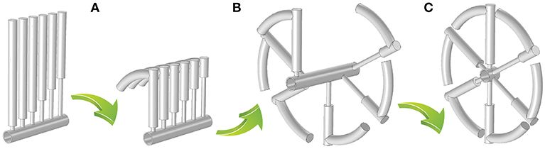
Figure 5. Transformation steps to replicate the “grozovik"-inspired design (see the symbol 7 in Figure 1A), including (A) coiling the HR cavities, (B) rotation of the HRs along the central axis of the tube, (C) shift of the HRs toward an open end of the tube.
Next, we rotate the folded HRs by 60°relative to each other (Figure 5B). Since the resonators act as point-like scatterers (Figure 1C), the panel absorption is again preserved as confirmed by the simulations.
Finally, the HRs are shifted toward the air domain, so that they have an identical z coordinate. Note that this transformation replaces the non-symmetric HR configuration by symmetric, since the order of the HRs becomes irrelevant. The simulations show that the system with the shifted HRs has a better absorption (the red curve in Figure 6). Namely, at the first five peaks, the absorption (frequency) increases by 20% (26%), 380% (0%), 195% (2%), 91% (4%), 28% (2%), and only at the sixth peak α decreases by 38%, while the corresponding frequency increases by 2%. Since the frequency of the first peak approaches the higher peaks, all the peaks are merged and form a continuous frequency range with non-zero absorption. The occurrence of a broadband absorption can be explained by interactions of the HRs sharing the spatial location, as compared to the “in-series” configuration. Figure 7 shows that every shifted HR is activated at each resonant peak, and thus, every HR contributes to the sound attenuation. In contrast, the “in-series” HRs are simultaneously excited only at the first peak, while at the higher-frequency peaks at least one HR is “switched off.” If the length of the cavity is reduced to L/6 = 15 mm (Figure 5C), the absorption has slightly lower values (the blue dashed line in Figure 6), but the panel thickness becomes 6 times smaller. Therefore, the arrangement of the HRs at the same spatial location appears to be an efficient means to increase the sound absorption, if the structural thickness should be minimized. We emphasize that several HRs with the same z coordinate are not equivalent to a single HR since the induced absorption is broadband in contrast to the individual peak of a single resonator.
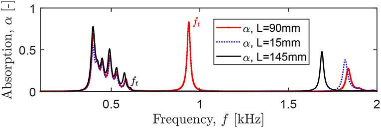
Figure 6. The absorption of a panel with folded HRs (with an identical z coordinate) placed close to an open end of the tube of varying length L. The ft indicates the cavity resonance at c0/4L.
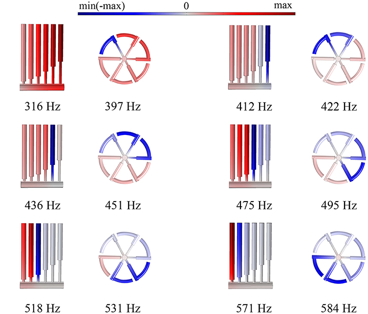
Figure 7. The pressure distributions at the absorption peaks shown in Figure 4, bottom and Figure 6.
Apart from the HR resonances, there is an additional absorption peak at 937 Hz, corresponding to the cavity resonance ft = c0/4L. It is characterized by a maximum pressure concentrated in the closed end of the cavity. This resonance can be used to improve the overall panel absorption by matching the frequency ft to the HR peaks (Jiménez et al., 2017b) and simultaneously folding the excessive length of the cavity in order to minimize the panel thickness. Indeed, for L = 145 mm, ft = 592 Hz that is close to the frequency of the sixth localized mode 583 Hz. The corresponding absorption (the black curve in Figure 6) is higher at the HR peaks, as compared to the configurations with the other L (the red and blue curves in Figure 6). However, the closer ft to the HR peaks, the smaller the absorption peak associated with ft: it almost disappears for L = 145 mm, since the energy of the cavity resonance is used to intensify the HR resonances.
We have shown that the use of interacting HRs sharing the spatial location allows substantially reducing the panel thickness, while the lateral sizes remain large. Such configurations can comply with the requirements for a wide range of engineering applications in room acoustics and noise reduction when the restrictions on the absorber thickness are severe. The lateral dimensions of the HRs can be further reduced. The presented configuration replicates the shape of the “grozovik” symbol (N. 7 in Figure 1A), while one can develop more compact designs, e.g., by folding the HR cavities into spirals as in Jiménez et al. (2017a).
The absorption ability of the panel can be further improved by periodically replicating the HRs along the z-axis direction (Jiménez et al., 2017a) or by superimposing the HRs of different dimensions (e.g., by imitating the structure of the symbol 6 in Figure 1A). Another approach implies a systematic optimization of the resonator geometry (Jiménez et al., 2016, 2017b), taking into account the coupling between the HRs. Since the number of HRs is not fixed and can be arbitrary, it opens many possibilities for various complex configurations with a sufficient amount of geometric parameters to increase the absorption to a desired level.
5. Coupled Resonators for Broadband Absorption at Different Frequency Ranges
In this section, we design and analyze absorbing panels with coupled HRs. A simple coupled resonator is obtained through the partition of the HR cavity by a supplementary neck. A peculiar property of a coupled HR is the presence of an absorption peak at subwavelength frequencies in addition to the peak originating from the first-order resonance of an unpartitioned HR.
As an illustrative example, we consider a cylindrical cavity loaded by a single HR (Figure 8A). The length of the cavity is Lt = 2 cm, and its radius is Rt = 7 mm. The lattice pitches are Lx = 10.9 cm and Ly = 15.1 cm (Figure 2A). The HR parameters Lr1 = 12 cm, Rr1 = 7.4 mm, Ln1 = 5 mm, and Rn1 = 6.75 mm are chosen to achieve a quasi-perfect absorption at the first resonant peak f1 = 589 Hz, α1 = 0.983 (the red line in Figure 8C). If the HR cavity is partitioned into two equal parts by a neck of length Ln2 = 1 mm and radius Rn2 = 2.75 mm (Figure 8B), there appears an additional peak at f2 = 1557 Hz with α2 = 0.885, while the first peak is shifted to a slightly lower frequency f1 = 553 Hz, α1 = 0.951 (the blue line in Figure 8C). The second peak originates from the second-order HR resonance shifted to lower frequencies due to added losses in the supplementary neck. Therefore, by varying the level of losses in the neck, one can tune the frequency f2 and absorption α2 to desired values. This feature enables the design of compact systems capable of absorbing sound at several frequency scales at the cost of a negligible increase of the HR length.
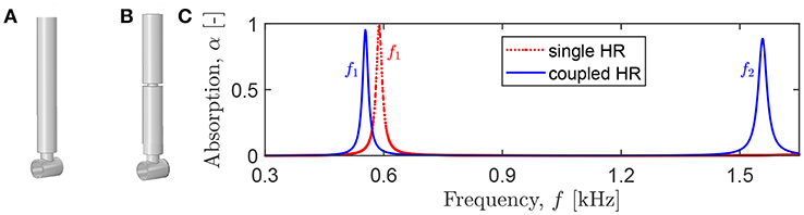
Figure 8. Rigidly backed cavity loaded by (A) a single HR (an initial configuration) and (B) a coupled HR. (C) The absorption coefficient for a panel with a rectangular lattice of cavities loaded by a single or a coupled HR.
To understand the influence of the neck geometry on the system absorption, we perform parametric studies for the panel with the coupled HR described above and the neck of Rn2 = 3.75 mm and Ln2 = 1 mm, if other values are not indicated. First, we vary the radius of the neck Rn2. Figure 9A shows that the smaller Rn2, the larger the shift of both absorption peaks to lower frequencies. Note that the corresponding absorption drastically decreases. Instead, for increasing Rn2, the first absorption peak closely approaches the values of f1 and α1 for the unpartitioned HR, while the second peak is shifted to higher frequencies with an unchanged absorption level. This behavior can be expected, as for large Rn2 the dynamics of the coupled HR becomes indistinguishable from that of the unpartitioned HR. Next, we change the position of the neck within the HR cavity. Figure 9B shows the first and second absorption peaks for the indicated length of the upper HR cavity Lr2. One can see that the location of the neck does not influence the absorption coefficient of the first resonance peak, while the corresponding frequency monotonically decreases with the increase of Lr2. For the second peak, the dependence is non-monotonic with the initial decrease of f2 and α2 for Lr2 < 6 cm and the subsequent increase for Lr2 > 6 cm. The observed dependence can be easily understood taking into account the pressure distribution at f1 and f2. Since for f1, the HR cavity is excited as a whole, with an equal maximum level of pressure along the cavity, the position of the supplementary neck cannot change this resonance significantly. For f2, the pressure has maximum out-of-phase values at the top and bottom of the HR cavity and close to zero levels in the middle. Thus, the location of the neck close to the top or bottom of the HR cavity results in larger absorption and higher resonant frequency. For further simulations, we choose Lr1 = 7 cm, Lr2 = 5 cm and analyze the influence of the length of the neck Ln2. For both peaks, the long necks result in lower frequencies of the absorption peaks and the slightly decreasing absorption level (Figure 9C). Obviously, longer necks increase the HR size and the cavity volume that leads to lower f1 and f2 and decreasing absorption. Finally, we estimate the influence of the position of the upper HR cavity on the system absorbing capability. We rotate the upper part of the HR by 90°and shift it along the cavity of the lower part. The distance between the upper end of the lower cavity and the central axis of the rotated part is designated as d (Figure 10A, left). The absorption graphs in Figure 10A show that if d increases, the values of f1 and α1 also increase, and one can even achieve perfect absorption, α1 = 1 when the upper cavity is close to the HR neck. Instead, for larger d, the absorption α2 decreases significantly, and f2 is shifted to lower values. The parametric studies reveal that the length of the supplementary neck Ln2 and the position of the upper HR cavity have a larger influence on the absorption than the other analyzed parameters. This can be exploited to design broadband absorbers working at several frequency ranges.
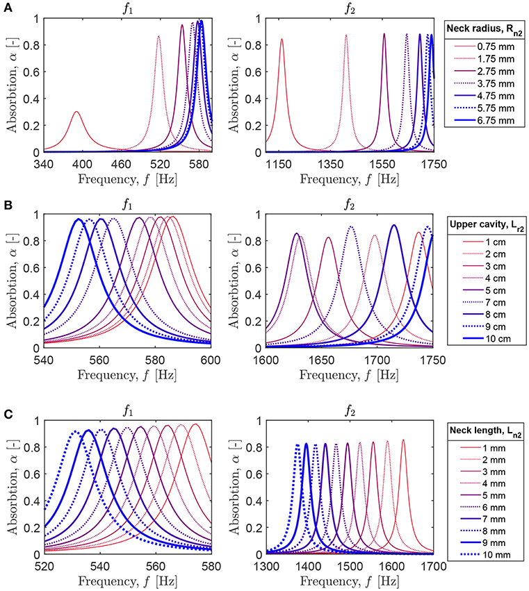
Figure 9. Parametric analysis of the geometry and position of the supplementary neck on the absorption of the panel with the coupled HR: the first (left) and second (right) absorption peaks for the varying (A) radius of the neck; (B) length of the upper HR cavity; (C) length of the neck.
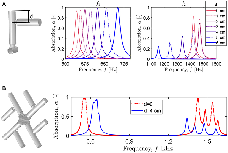
Figure 10. (A) The absorption peaks for the varying position of the upper part of the coupled HR relative to the lower part. (B) The absorption coefficient of a configuration with four coupled HRs of identical geometry, except the length of the supplementary neck: mm, mm, mm, and mm.
For instance, we use four coupled resonators loading four identical cavities (Figure 10B). The geometric parameters for the cavities and the HRs are the same as described above. The only difference between the coupled HR is in the length of the supplementary neck: 2 mm, 3 mm, 5 mm, and 7 mm. The center-to-center distance between the adjacent cavities is Rt. When the upper HR cavities are shifted at d = 4 cm, so that the designed structure (Figure 10B, on the left) resembles the symbol “kolard” (the symbol 4 in Figure 1A), the corresponding system exhibits broadband 90% absorption at 625–655 Hz, and four additional absorption peaks at 1,345, 1,430, 1,478, and 1,567 Hz. For d = 0 cm, the absorption is almost quasi-perfect, exceeding 95%, between 542 and 562 Hz, and, in addition, there occurs a broadband range with absorption exceeding 25% between 1400 Hz-1590 Hz. Obviously, one can further optimize the system geometry to achieve perfect absorption or to broaden the absorption frequency ranges. However, this example already reveals important advantages of the coupled HRs: the negligible increase of the HR size due to the insertion of a supplementary neck allows to achieve broadband sound absorption at several frequency ranges in contrast to a single frequency range typical for unpartitioned HRs (Jiménez et al., 2017a,b).
6. Conclusions
In this work, we numerically investigated two approaches for broadening the sound absorption of acoustic metamaterial panels with incorporated HRs. The first approach relies on interactions of the HRs sharing a spatial locationthat result in merging of isolated absorption peaks. The second approach exploits the concept of coupled resonators with a supplementary neck introduced in the HR cavity. We show that the panels with coupled HRs can attenuate broadband sound at several subwavelength frequency ranges. The considered design approaches are suitable for panels with severe restrictions on the structural thickness, while lateral dimensions can be large.
We propose to exploit the plane geometry of a panel (normal to the thickness direction) for decorative purposes, in addition to its acoustic functionality. Specifically, we analyzed the panels with the HR appearance replicating ancient Slavic patterns composed of periodic repetitions of traditional symbols. The modern manufacturing techniques allow easy and inexpensive implementation of these designs in practical configurations. Figure 11 shows an example of a panel with the Slavic-inspired HRs in a room interior. In this design, the combination of the “grozovik” and “yashur” symbols implements the discussed concepts of interacting and coupled HRs. (The middle row in the panel of Figure 11 is obtained by the superposition of the “yashur” symbol and its mirror-reflected counterpart.) The panel is made of a transparent material (e.g., polylactic acid) with a red background, while the perforated cavities and HR interiors are colored in black and metallic white. Given an almost unlimited choice of symbolic and other designs, numerous panel configurations are possible, in which the HR geometries and form can be adjusted to working frequency ranges and target environment. In this way, decorated absorbing panels can not only control acoustic properties of a surrounding environment but also inspire the creativity of designers, who actively work on creating functional artworks.

Figure 11. An example of the metamaterial panel in a room (thanks to “https://pixnio.com” for an original image).
We finally note that the ideas of combining smart materials, art and advanced functionalities are central to the modern architecture and interior design. Recent examples include sun-shade screens of Al-Bahar towers in Abu-Dhabi, the Hapra concert hall in Reykjavik with a lattice-type exterior harnessing the sunlight, and a renovated concert hall of Tokyo National University of Fine Art and Music with the ceiling decoration working as an acoustic system. We hope that the proposed Slavic-inspired designs of acoustic absorbers will contribute to a wider practical implementation of the metamaterial-based systems.
Author Contributions
AK designed the research, conducted the analysis, and wrote the manuscript.
Funding
The support of COST Action DENORMS CA15125 funded by COST (European Cooperation in Science and Technology), grant No. 40013 was appreciated.
Conflict of Interest Statement
The author declares that the research was conducted in the absence of any commercial or financial relationships that could be construed as a potential conflict of interest.
Acknowledgments
The author gratefully acknowledges the support of the Laboratoire de l'Université du Mans (France) with the simulations and inspiring discussions with Dr. J.-P. Groby and Dr. V. Romero-García from the same university.
References
Allard, J., and Atalla, N. (2009). Propagation of Sound in Porous Media: Modelling Sound Absorbing Materials. Chichester, UK: Willey.
Brunet, T., Merlin, A., Mascaro, V., Zimny, K., Leng, J., Poncelet, O., et al. (2015). Soft 3D acoustic metamaterial with negative index. Nat. Mater. 14:384. doi: 10.1038/nmat4164
Craster, R. V., and Guenneau, S. (2012). Acoustic Metamaterials: Negative Refraction, Imaging, Lensing and Cloaking. Heidelberg: Springer.
Cummer, S. A., Christensen, J., and Alu, A. (2016). Controlling sound with acoustic metamaterials. Nat. Rev. Mater. 1:16001. doi: 10.1038/natrevmats.2016.1
Deymier, P. A. (Ed). (2013). Acoustic Metamaterials and Phononic Crystals. Berlin; Heidelberg: Springer.
Fang, N., Xi, D., Xu, J., Ambati, M., Srituravanich, W., Sun, C., et al. (2006). Ultrasonic metamaterials with negative modulus. Nat. Mater. 5, 452–456. doi: 10.1038/nmat1644
Fleury, R., Sounas, D. L., Sieck, C. F., Haberman, M. R., and Alu, A. (2014). Sound isolation and giant linear nonreciprocity in a compact acoustic circulator. Science 343, 516–519. doi: 10.1126/science.1246957
Gao, N., Wu, J. H., Hou, H., and Yu, L. (2017). Excellent low-frequency sound absorption of radial membrane acoustic metamaterial. Int. J. Mod. Phys. B 30:1750011. doi: 10.1142/S0217979217500114
Groby, J.-P., Lagarrigue, C., Brouard, B., Dazel, O., and Tournat, V. (2015). Enhancing the absorption properties of acoustic porous plates by periodically embedding Helmholtz resonators. J. Acoust. Soc. Am. 137, 273–280. doi: 10.1121/1.4904534
Groby, J.-P., Pommier, R., and Aurégan, Y. (2016). Use of slow sound to design perfect and broadband passive sound absorbing materials. J. Acoust. Soc. Am. 139, 1660–1667. doi: 10.1121/1.4945101
Guenneau, S., Movchan, A., Pétursson, G., and Ramakrishna, S. A. (2007). Acoustic metamaterials for sound focusing and confinement. New J. Phys. 9:399. doi: 10.1088/1367-2630/9/11/399
Holloway, C. L., Kuester, E. F., Gordon, J. A., O'Hara, J., Booth, J., and Smith, D. R. (2012). An overview of the theory and applications of metasurfaces: the two-dimensional equivalents of metamaterials. IEEE Antenn. Propag. M54, 10–35. doi: 10.1109/MAP.2012.6230714
Jia, Z., Li, J., Shen, C., Xie, Y., and Cummer, S. A. (2018). Systematic design of broadband path-coiling acoustic metamaterials. J. Appl. Phys. 123:025101. doi: 10.1063/1.5009488
Jiang, X., Liang, B., Li, R.-Q., Zhou, X.-Y., Yin, L.-L., and Cheng, J.-C. (2014). Ultra-broadband absorption by acoustic metamaterials. Appl. Phys. Lett. 105:243505. doi: 10.1063/1.4904887
Jiménez, N., Cox, T. J., Romero-García, V., and Groby, J.-P. (2017c). Metadiffusers: deep-subwavelength sound diffusers. Sci. Rep. 7:5389. doi: 10.1038/s41598-017-05710-5
Jiménez, N., Huang, W., Romero-García, V., Pagneux, V., and Groby, J.-P. (2016). Ultra-thin metamaterial for perfect and quasi-omnidirectional sound absorption. Appl. Phys. Lett. 109:121902. doi: 10.1063/1.4962328
Jiménez, N., Romero-García, V., Pagneux, V., and Groby, J.-P. (2017a). Quasiperfect absorption by subwavelength acoustic panels in transmission using accumulation of resonances due to slow sound. Phys. Rev. B 95:014205. doi: 10.1103/PhysRevB.95.014205
Jiménez, N., Romero-García, V., Pagneux, V., and Groby, J. P. (2017b). Rainbow-trapping absorbers: broadband, perfect and asymmetric sound absorption by subwavelength panels for transmission problems. Sci. Rep. 7:13595. doi: 10.1038/s41598-017-13706-4
Kaina, N., Lemoult, F., Fink, M., and Lerosey, G. (2015). Negative refractive index and acoustic superlens from multiple scattering in single negative metamaterials. Nature 525:77. doi: 10.1038/nature14678
Kan, W., Liang, B., Li, R., Jiang, X., Zou, X., Yin, L., et al. (2016). Three-dimensional broadband acoustic illusion cloak for sound-hard boundaries of curved geometries. Sci. Rep. 6:36936. doi: 10.1038/srep36936
Krushynska, A. O. (2019). COMSOL Dataset for the Paper “Between Science and Art: Thin Sound Absorbers Inspired by Slavic Ornaments” by A. O. Krushynska. DataverseNL, V1. Available online at: https://hdl.handle.net/10411/L5G6K0 (accessed July 8, 2019).
Krushynska, A. O., Bosia, F., Miniaci, M., and Pugno, N. M. (2017). Spider web-structured labyrinthine acoustic metamaterials for low-frequency sound control. New J. Phys. 19:105001. doi: 10.1088/1367-2630/aa83f3
Krushynska, A. O., Bosia, F., and Pugno, N. M. (2018). Labyrinthine acoustic metamaterials with space-coiling channels for low-frequency sound control. Acta Acust. United With Acust. 104, 200–210. doi: 10.3813/AAA.919161
Li, J. S., Fok, L., Yin, X. B., Bartal, G., and Zhang, X. (2009). Experimental demonstration of an acoustic magnifying hyperlens. Nat. Mater. 8, 931–934. doi: 10.1038/nmat2561
Li, J. S., and Pendry, J. B. (2008). Hiding under the carpet: a new strategy for cloaking. Phys. Rev. Lett. 101:203901. doi: 10.1103/PhysRevLett.101.203901
Li, Y., Jiang, X., Li, R. Q., Liang, B., Zou, X. Y., Yin, L. L., et al. (2014). Experimental realization of full control of reflected waves with subwavelength acoustic metasurfaces. Phys. Rev. Appl. 2, 1–11. doi: 10.1103/PhysRevApplied.2.064002
Li, Y., Jiang, X., Liang, B., Cheng, J. C., and Zhang, L. (2015). Metascreen-based acoustic passive phased array. Phys. Rev. Appl. 4:024003. doi: 10.1103/PhysRevApplied.4.024003
Li, Y., Liang, B., Gu, Z. M., Zou, X. Y., and Cheng, J. C. (2013). Reflected wavefront manipulation based on ultrathin planar acoustic metasurfaces. Sci. Rep. 3:2546. doi: 10.1038/srep02546
Li, Y., Liang, B., Tao, X., Zhu, X. F., Zou, X. Y., and Cheng, J. C. (2012). Acoustic focusing by coiling up space. Appl. Phys. Lett. 101:233508. doi: 10.1063/1.4769984
Liang, B., Cheng, J.-C., and Qui, C.-W. (2018). Wavefront manipulation by acoustic metasurfaces: from physics and applications. Nanophotonics 7, 1191–1205. doi: 10.1515/nanoph-2017-0122
Liang, B., Guo, X. S., Tu, J., Zhang, D., and Cheng, J. C. (2010). An acoustic rectifier. Nat. Mater. 9, 989–992. doi: 10.1038/nmat2881
Liang, Z., and Li, J. (2012). Extreme acoustic metamaterial by coiling up space. Phys. Rev. Lett. 108:114301. doi: 10.1103/PhysRevLett.108.114301
Liu, Z., Zhang, X., Mao, Y., Zhu, Y.-Y., Yang, Z., Chan, C.-T., et al. (2000). Locally resonant sonic materials. Science 289, 1734–1736. doi: 10.1126/science.289.5485.1734
Lu, K., Wu, J. H., Guan, D., Gao, N., and Li, J. (2016). A lightweight low-frequency sound insulation membrane-type acoustic metamaterial. AIP Adv. 6:025116. doi: 10.1063/1.4942513
Ma, F., Huang, M., and Wu, J. H. (2017). Acoustic metamaterials with synergetic coupling. J. Appl. Phys. 122:215102. doi: 10.1063/1.5003276
Ma, F., Huang, M., Xu, Y., and Wu, J. H. (2018). Bilayer synergetic coupling double negative acoustic metasurface and cloak. Sci. Rep. 8, 1–12. doi: 10.1038/s41598-018-24231-3
Mei, J., Ma, G., Yang, M., Yang, Z., Wen, W., and Sheng, P. (2012). Dark acoustic metamaterials as super absorbers for low-frequency sound. Nat. Commun. 3:756. doi: 10.1038/ncomms1758
Merkel, A., Theocharis, G., Richoux, O., Romero-García, V., and Pagneux, V. (2015). Control of acoustic absorption in one-dimensional scattering by resonant scatterers. Appl. Phys. Lett. 107:244102. doi: 10.1063/1.4938121
Molerón, M., Serra-García, M., and Daraio, C. (2016). Visco-thermal effects in acoustic metamaterials: from total transmission to total reflection and high absorption. New J. Phys. 18:033003. doi: 10.1088/1367-2630/18/3/033003
Park, C. M., Park, J. J., Lee, S. H., Seo, Y. M., Kim, C. K., and Lee, S. H. (2011). Amplification of acoustic evanescent waves using metamaterial slabs. Phys. Rev. Lett. 107:194301. doi: 10.1103/PhysRevLett.107.194301
Romero-García, V., Theocharis, G., Richoux, O., Merkel, A., Tournat, V., and Pagneux, V. (2016). Perfect and broadband acoustic absorption by critically coupled sub-wavelength resonators. Sci. Rep. 6:19519. doi: 10.1038/srep19519
Tang, Y., Ren, S., Meng, H., Xin, F., Huang, L., Chen, T., et al. (2017). Hybrid acoustic metamaterial as super absorber for broadband low-frequency sound. Sci. Rep. 7:43340. doi: 10.1038/srep43340
Theocharis, G., Richoux, O., Romero-García, V., Merkel, A., and Tournat, V. (2014). Limits of slow sound propagation and transparency in lossy, locally resonant periodic structures. New J. Phys. 16:093017. doi: 10.1088/1367-2630/16/9/093017
Wu, Y., Yang, M., and Sheng, P. (2018). Perspective: acoustic metamaterials in transition. J. Appl. Phys. 123:090901. doi: 10.1063/1.5007682
Xie, Y., Popa, B.-I., Zigoneanu, L., and Cummer, S. (2013). Measurement of a broadband negative index with space-coiling acoustic metamaterials. Phys. Rev. Lett. 110:175501. doi: 10.1103/PhysRevLett.110.175501
Xie, Y., Wang, W., Chen, H., Konneker, A., Popa, B. I., and Cummer, S. A. (2014). Wavefront modulation and subwavelength diffractive acoustics with an acoustic metasurface. Nat. Commun. 5:5553. doi: 10.1038/ncomms6553
Yang, M., Chen, S., Fu, C., and Sheng, P. (2017). Optimal sound-absorbing structures. Mater. Horizons 4, 673–680. doi: 10.1039/C7MH00129K
Yang, M., Meng, C., Fu, C., Li, Y., Yang, Z., and Sheng, P. (2015). Subwavelength total acoustic absorption with degenerate resonators. Appl. Phys. Lett. 107:104104. doi: 10.1063/1.4930944
Yang, Z., Mei, J., Yang, M., Chan, N. H., and Sheng, P. (2008). Membrane-type acoustic metamaterial with negative dynamic mass. Phys. Rev. Lett. 101:204301. doi: 10.1103/PhysRevLett.101.204301
Zhang, C., and Hu, X. (2016). Three-dimensional single-port labyrinthine acoustic metamaterial: perfect absorption with large bandwidth and tunability. Phys. Rev. Appl. 6:064025. doi: 10.1103/PhysRevApplied.6.064025
Appendix: Numerical Analysis
The dispersion and transmission analyses are performed by means of eigenfrequency and frequency domain studies in the Acoustic Pressure module in COMSOL Multiphysics. The models are represented by discretized geometries of the panel cavities and outside air, while the presence of panels is replicated by the sound hard boundary conditions. The outside-air domain has the width Lx, the height Ly, and the depth Lz = 3 ∗ max{Lx, Ly}, where the latter is chosen to exclude from the consideration near-field effects. Incident waves are represented by a background plane-wave field of a unit amplitude within all the domains. At the side of the outside-air domain opposite to the panel, plane-wave radiation conditions are applied. The air inside the cavities and HRs is discretized by means of free-mesh tetrahedral elements; for outside air, the swept mesh is used.
The dispersion analysis is done by a parametric sweep from 0 to π/Lt with 15 values. The transmission simulations are performed within specified frequency ranges by solving the frequency-domain problem at 2,000 intermediate frequencies. The transmitted pressure field is extracted at two domain point probes with coordinates (0, 0, Lz) and (0, 0, Lz−0.01) that allows evaluation the reflection coefficient by means of Equation (3).
Keywords: wave dynamics, acoustic metamaterial, Helmholtz resonator, sound absorption, dispersion, Slavic ornament
Citation: Krushynska AO (2019) Between Science and Art: Thin Sound Absorbers Inspired by Slavic Ornaments. Front. Mater. 6:182. doi: 10.3389/fmats.2019.00182
Received: 27 November 2018; Accepted: 10 July 2019;
Published: 13 August 2019.
Edited by:
Asa Barber, London South Bank University, United KingdomReviewed by:
Ettore Barbieri, Japan Agency for Marine-Earth Science and Technology, JapanDomenico De Tommasi, Politecnico di Bari, Italy
Copyright © 2019 Krushynska. This is an open-access article distributed under the terms of the Creative Commons Attribution License (CC BY). The use, distribution or reproduction in other forums is permitted, provided the original author(s) and the copyright owner(s) are credited and that the original publication in this journal is cited, in accordance with accepted academic practice. No use, distribution or reproduction is permitted which does not comply with these terms.
*Correspondence: Anastasiia O. Krushynska, a.o.krushynska@rug.nl