Buckling Behavior of Poly-Phenylene-Sulfide/Carbon L-Shaped Stringers and a Stiffened Panel Obtained by Induction Welding
 Gennaro Scarselli
 Silvio Pappadà
 Giuseppe Buccoliero
 Alfonso Maffezzoli
- 1Department of Engineering for Innovation, University of Salento, Lecce, Italy
- 2Advanced Materials & Processes Consulting, CETMA-Technologies Design and Materials European Research Center, Brindisi, Italy
Although the high performance thermoplastics matrix composites have been studied for more than 30 years, only recently their advantages have been properly perceived and exploited, for a wide range of applications either in secondary either in primary aeronautical structures. In this work, compression testing of a flat panel stiffened with L-shaped stringers made of poly-phenylene-sulfide (PPS) matrix reinforced with carbon fibers is presented. The stiffeners were joined to the base plate by induction welding, as reported in a former study. The numerical activities, aimed at static, buckling and post-buckling analysis, first of a single stringer, then of the stiffened panel under compressive load, provided results in good agreement with the experimental ones. The analyses were performed taking into account either for the geometric non-linearity associated with the large deformations of the structures under the action of compressive loads either for the local buckling of the flanges composing the stringers. Experimental activities were aimed at the characterization of the adopted materials with a special focus on the determination of buckling loads either of an L-shaped stringer either of a panel stiffened with four stingers. In both cases, an excellent structural behavior was shown, the panel and a single stringer being able to take huge loads after the first buckling appeared. The panel, in particular, showed an excellent post-buckling strength and broke by buckling failure of stringers. The welded interfaces did not fail indicating that thermoplastic welding is a suitable technique for assembly composite structural elements.
Introduction
High performance thermoplastic matrix composites are gaining more and more attention in several engineering applications such as aerospace, wind turbines, and automotive industries. Consequently, researchers and scientists are focusing on properties, technology, and design issues needed to fully exploit them (Erber and Spitko, 2014; Mathijsen, 2016). Over the last 30 years, thermosetting matrix composites were preferred by the aerospace designers thanks to their dimensional stability at high temperature, since they not melt. In comparison, thermoplastic matrices can melt at temperatures slightly higher than the maximum operational ones. More recently, thermoplastics joined thermosets in the comfort zone of the aerospace designers. An example of such a change of perspective is given by the tail plane of the Gulfstream 650 or the leading edge of A380 and A340 both made with poly-phenylene-sulfide (PPS) matrix reinforced with carbon and glass fibers, respectively. Assembly by induction and resistance welding was adopted for these components (Offringa, 2005).
Generally speaking, without any reference to a specific industrial field, there are different metrics that can be used for comparing thermosets to thermoplastics. This comparison can be summarized as follows. Thermosets are generally more resistant to high temperatures than thermoplastics, show high levels of dimensional stability, and are still more cost effective. On the other hand, they cannot be recycled or re-molded and reshaped upon heating. Thermoplastics, instead, offer potential recyclability, higher impact-resistance, can be re-molded and reshaped upon heating, and can be manufactured in shorter cycle times. Their cons are that, at the moment, they are more expensive than thermosets and can melt upon heating above melting point. Many papers were published over the last years comparing the performance of thermosets and thermoplastics-based composites (Vieille et al., 2013; Nishida et al., 2018; Sun et al., 2018). An extensive analysis on low velocity impact effects on carbon woven-ply reinforced polymer composites was presented in Vieille et al. (2013). The main outcomes were that carbon/epoxy laminates suffered larger delamination than carbon/thermoplastic ones. In the latter, reduced damages were found after C-scans (especially in carbon/PPS laminates), confirming that tougher matrices can turn in better impact performances. Thermoset and thermoplastic-based carbon fiber composite panels were experimentally and numerically compared looking at their behavior under low impact velocity in reference (Sun et al., 2018). Two key impact energies (8 and 30 J) were considered. The thermoplastic matrix composites, in this specific case, surprisingly did not have noticeably better behavior than the thermoset counterpart and unstable propagation of cracks for the same impact energy was found. A comparison of the mechanical features of thermoplastic and thermoset epoxy matrix carbon textile composites was reported by Nishida et al. (2018). The composite with high molecular weight thermoplastic epoxy, merging the best features of linear polymers and epoxy chemistry, showed improved mechanical performances than conventional thermoset epoxy composites.
One of the main challenges related to industrial applications of thermoplastics is their joining. If rivets or bolts should be avoided, since they weaken the laminate and increase the weight of the assembled components, on the other hand, the low surface energy of thermoplastic matrix surfaces limits the use of adhesive bonding unless preliminary activating techniques (i.e., plasma, UV, and so on) are applied (Encinas et al., 2014). A distinctive alternative is given by welding that provides excellent joint efficiency but in presence of some minor and manageable drawbacks such as thermal residual stresses, limited thickness of the parts to be joined (according to the power of the available equipment), costs still relatively higher, geometric limitations. Many different types of welding techniques have been applied for joining composites: electric resistance, electromagnetic induction, ultrasonic, vibration, dielectric/microwave, and infrared welding (Loos et al., 1980; Wang and Hahn, 2007; Mouzakis et al., 2008). As reported by da Costa et al. (2012), a single welding technique cannot necessarily fit all the different industrial situations since all the methods present advantages and drawbacks. The most mature techniques are ultrasonic, induction, and resistance welding.
Primary structures of aircrafts must be able to withstand torsion, shear, and bending and their structure can be regarded as a torsion hollow box. Such kinds of structures are made of stiffened plates involving components subjected to significant compressive stresses. This peculiar stress field can lead to the buckling, global or local, of the different structural parts. Co-curing and co-bonding of the stringers are often the adopted solutions when thermosetting matrix composites are used, even if bolted joints are still the most used and reliable joining technique (Maffezzoli et al., 1989; Yousefpour et al., 2004; Pappadà et al., 2015; Scarselli et al., 2015; Zhao et al., 2017).
The buckling behavior of stiffened panels was studied by different authors combining numerical and experimental activities. In particular, these studies were focused on the investigation of the compression performances from one (Kong et al., 1998; Perret et al., 2012) up to three (Mo et al., 2016) panels.
In this work, a PPS matrix composite reinforced with carbon fibers was used for building a typical flat panel stiffened with L-shaped stringers. The panel was designed according to a quasi-full scale aeronautic configuration and the stringers were joined to the panel by induction welding. The goals of the design were to prove the capability of the structure to withstandhigh compressive loads in post-buckling regime without failures at the welded interface between stringers and the base laminate. Moreover, the behavior of an L-shaped stringer in the post-buckling regime was tested and proper numerical models were proposed to describe the structural instability of the stiffened panel. To the best of our knowledge, all the studies available in the literature deal with thermoset composites; therefore, there is no evidence of other published buckling tests carried out on thermoplastic matrix composite panels. Furthermore, this study addresses the buckling properties of a panel where induction welding was used to bond stringers to base laminate. In addition, the reported structural instability of the clamped L-shaped stringer and stiffened panel demonstrated the superior post-buckling behavior of a thermoplastic component.
Materials and Methods
L-shaped stringers and a thermoplastic matrix composite flat panel, stiffened with these stringers, have been tested under compression loads. The test on stringers was aimed to better understand their bearing capability for further design purposes. Since the flat panel without stringers would buckle at relatively small compressive loads, stiffeners are required and their number is a function of the target buckling load. A sketch of tested components is shown in Figures 1A,B.
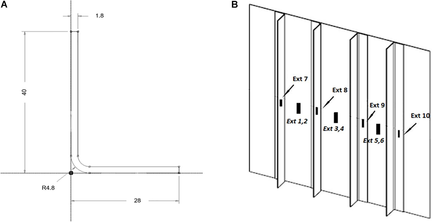
Figure 1. (A) L-shaped stringer geometry (flange 1 is the horizontal one; flange 2 is the vertical one). (B) Stiffened panel equipped with extensimeters for the compressive test.
The stiffened panel was obtained using CETEX® carbon-fiber fabric reinforced PPS prepreg, provided by TENCATE (5-harness satin; fiber volume fraction: 50%). A 500 × 500 mm flat laminate, characterized by a thickness of 1.2 mm was used as base plate (lay-up: [±45/0/90/0/90/±45]). Stringers were obtained by match die molding from 1.8 mm thick laminates (lay-up: [0/90/0/90/0/90/0/90]S). The L-shaped stringers used in compression tests were 400 mm long. The method used for joining the stiffeners to the panel is based on a patented induction welding process developed at CETMA (Brindisi, Italy). Welding of the stringers to the panel was performed using a 600 kHz, 220 V induction generator, designed and developed by CETMA and Sinergo (Italy). A “double-D” coil was used for welding the stiffeners. A coil distance from the surface of 2 mm was adopted and power was set at 1.25 kW, at a frequency of 600 kHz with a tension of 220 V. The welding speed was of 2 mm/s. Further details about the fabrication of the prototype and process modeling have been reported in a former paper (Pappadà et al., 2015). Buckling and post-buckling behavior of the stiffened panel and of stringers were characterized performing compression tests with a dynamometer MTS equipped with a load cell of 100 kN. Four extensimeters were used during stringers compression tests and 10 for the stiffened panel (see Figures 2, 4). The out-of-plane displacement of the flat panel was monitored using two LVDT.
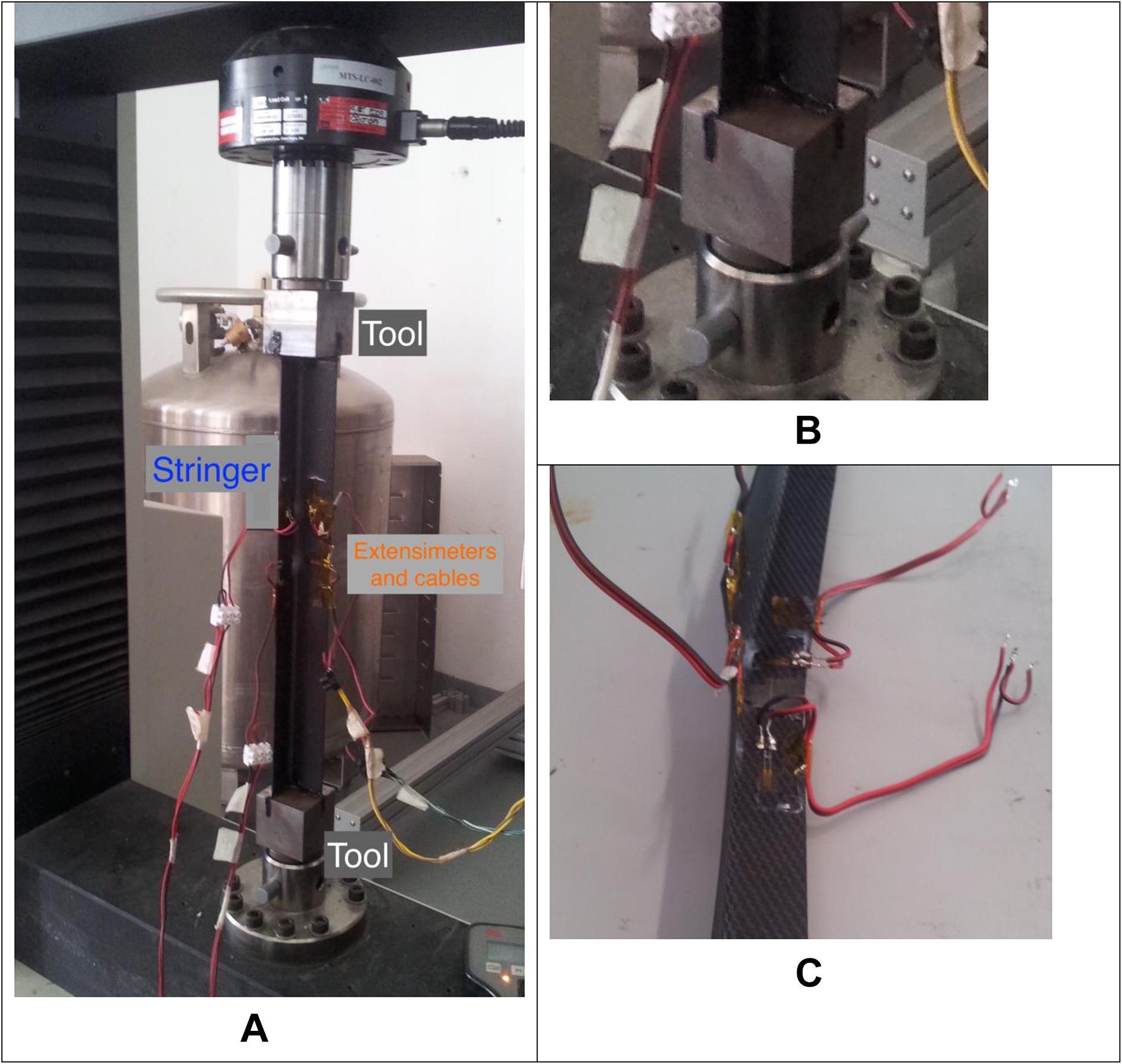
Figure 2. (A) Experimental set-up for buckling test of a stringer. (B) Enlarged picture of a tool with an L-shaped slot. (C) Failure section of a stringer after the buckling test.
Experimental Results
The capability of the welded joints in the stiffened panel to withstand the external loads without local failures under a typical loading condition in aeronautic structures was tested. Among other processing related issues, residual thermal stress induced during the welding could lead to weak points and delaminations impairing the overall buckling capability of the stiffened panel. There is not evidence of such types of experimentations in the technical literature even though industrial activities on full scale stiffened panels, obtained joining stringers or ribs by fasteners or adhesive bonding, are routinely performed.
The L-shaped stringer subjected to compressive load can exhibit the following unstable behaviors:
(1) Global buckling (as an Euler beam)—flexural;
(2) Global buckling—flexural/torsional;
(3) Local buckling (buckle wavelength of the same size of a cross-sectional dimension).
The flexural/torsional buckling is possible for one-dimensional elements having low torsional stiffness: if the boundary conditions allow to some extent the torsion of the beam sections, such kind of buckling must be taken into account. If the end sections are firmly clamped, and the torsion is prevented, suck kind of buckling will not occur. The local buckling in thin walled beams, like the L-shaped stringers here studied, is more likely to occur. This buckling mechanism depends on the relative stiffness between the plate elements forming the beam and the overall bending stiffness of the beam as a whole. The same considerations apply to the stiffened panel that can buckle globally or locally.
L-Shaped Stringers
The experimental set-up adopted for testing L-shaped stringers is reported in Figures 2A,B. Customized tools with an L-shaped slot for properly clamping the end sections of the stringer were manufactured. These tools prevented lateral translation, rotation, and torsion of these sections excluding the possibility that a flexural/torsion buckling of the beam occurs. Strains were measured using two extensimeters on each of the two flanges of the component. Figure 3 reports the load–displacement curve recorded during the buckling test of the stringers. The axial displacement is that of the cross-head of the testing machine. The load increases with two different main slopes up to the buckling load which was observed at about 8000 N. Then a relatively long flat region is shown in Figure 3 where the load was almost constant while the crosshead is still moving and the stringer is undergoing a buckling bending distortion. The results of Figure 3 are typical of a good post-buckling behavior, then the stringer failed showing fibers breakage at about the mid span and the test was interrupted (Figure 2C).
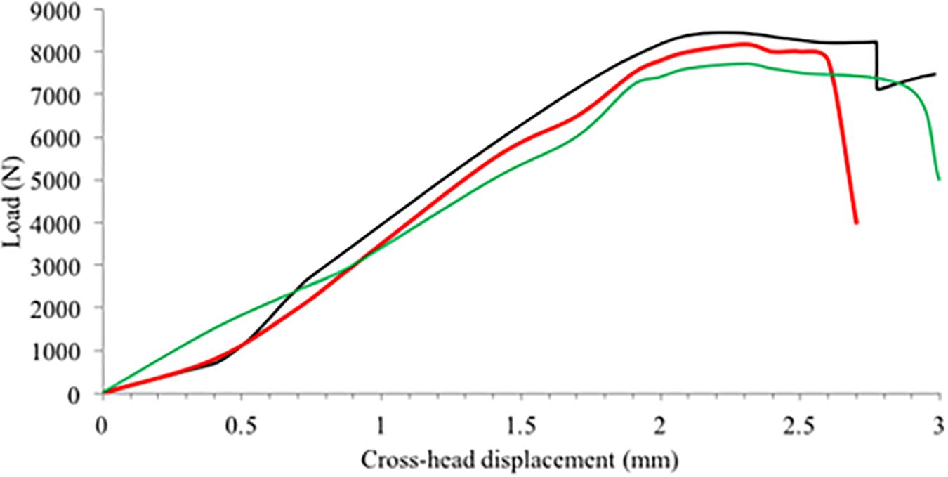
Figure 3. Load–displacement curves in a compression test performed on stringers.
Stiffened Panel
Buckling and post-buckling behavior of the stiffened panel was studied in a compression test. The compression load was simultaneously applied at the edges of the base panel and stringers, adopting custom made fixtures, as shown in Figure 4. As shown in Figure 5, the first buckling, appeared at about 10 kN, was attributed to a local buckling involving only a small part of the panel, i.e., the two unrestrained edges as suggested by the numerical simulations reported below, and not clearly visible in the load–displacement curve except for a small slope decrease. Afterward, the panel was able to withstand further incremental loads. The first global buckling load appeared at about 50 kN and was followed by significant out of plane displacements leading to the failure of stringers (Figure 6). The following typical features of a buckling test can be found in Figure 5:
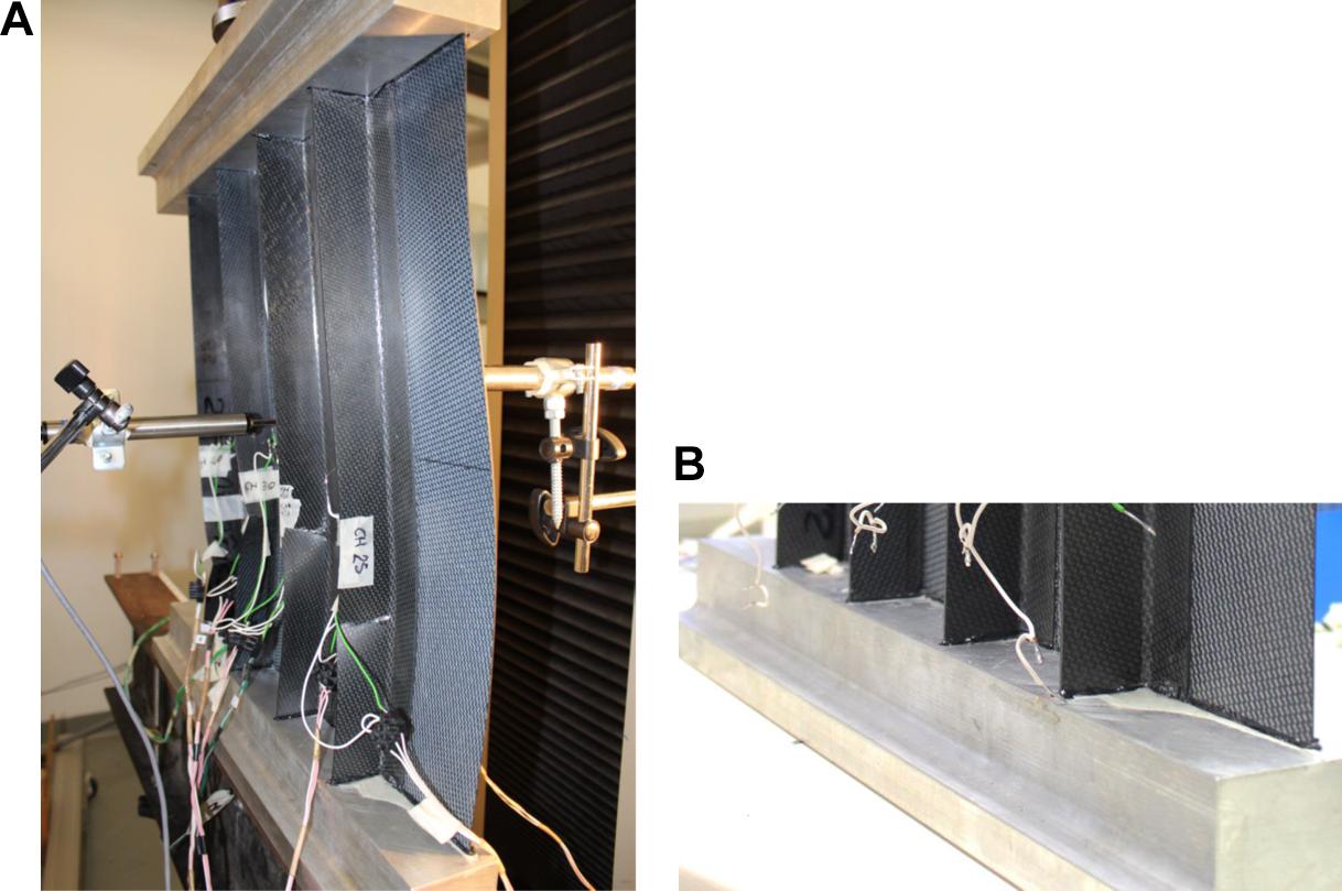
Figure 4. (A) Set-up of the compression test. Buckling of the unrestrained edge of the base laminate is evident. (B) Enlargement of the used tools.
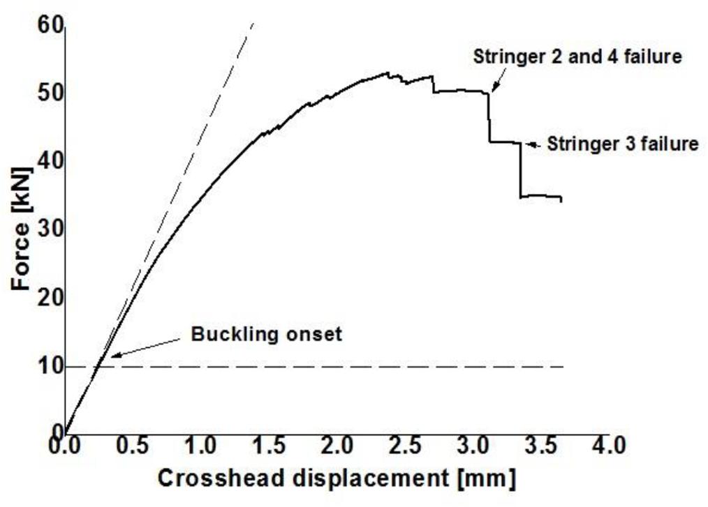
Figure 5. Load–displacement curve obtained from compression test on the stiffened panel.
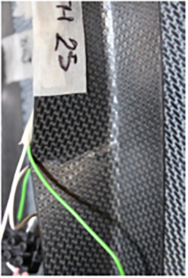
Figure 6. Failure of one of the stringer due to buckling. Debonding at the welded area between the stringer and the panel was not observed.
• The non-linear structural behavior of the whole stiffened panel derived from geometric non-linearities and resulted in a non-linear load–displacement curve, due essentially to the involved large deformations;
• In the load interval between 40 and 50 kN, the slope in Figure 5 decreases approaching global buckling failure of the panel. While the load is still increasing, the oscillations observed in Figure 5 can be attributed either to microfailures in the composite laminate either to the activation of additional buckling modes in the base plate and stringer flanges (Perret et al., 2012). These last, as shown below, are responsible of the first buckling load of stringers tested under compression.
• A flat region due to the transition at the buckling load from a stable geometric configuration to another one without incremental load.
The main result of the experimental tests has been that the panel-to-stringers welded joints withstood properly the compressive load throughout the test. The failure of the panel involved essentially the stringers flange that, under the action of the compressive load, eccentric at large deformations, bended until the rupture occurs. As reported in Figure 6, showing the area close to that of failure of a stringer, debonding of the induction welded contact area between the base panel and stringers was not observed, even after the buckling test was ended as a consequence of failures in all stringers.
Characterization of the Materials
The material characterization was aimed at obtaining the properties to be used for the analytical/numerical simulations. Two different laminate characterized by the lay-up adopted for the stiffener ([±45/0/90/0/90/±45]S) and the base plate ([0/90/0/90/0/90/0/90]S), were tested. Uniaxial tests were performed according to ASTM 3039 to measure the longitudinal elastic modulus. A picture of samples with an extensimeter and a typical stress/strain curve, either for the stringer either for the base plate lay-up, is reported in Figures 7, 8. Calculated (Ex,calc) and experimental (Ex,exp) values for both laminates are very close as reported in Table 1. The former ones were obtained by analytical calculations based on micromechanics for the properties of the lamina and on the classical lamination theory for those of the (Mallick, 2007; Jones, 2014). Lamina properties used for the computations are reported in Table 1. The adopted lay-up led to a linear behavior and similar values of longitudinal and transversal moduli of the laminates. The relevant values for the analytical/numerical models were averaged over the five tested samples.
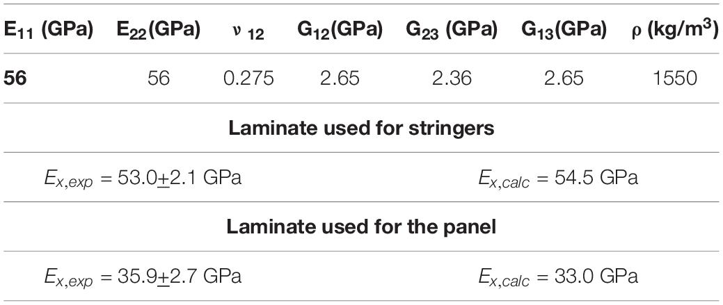
Table 1. Properties of fabric lamina and comparison between calculated and experimental moduli in global coordinates.
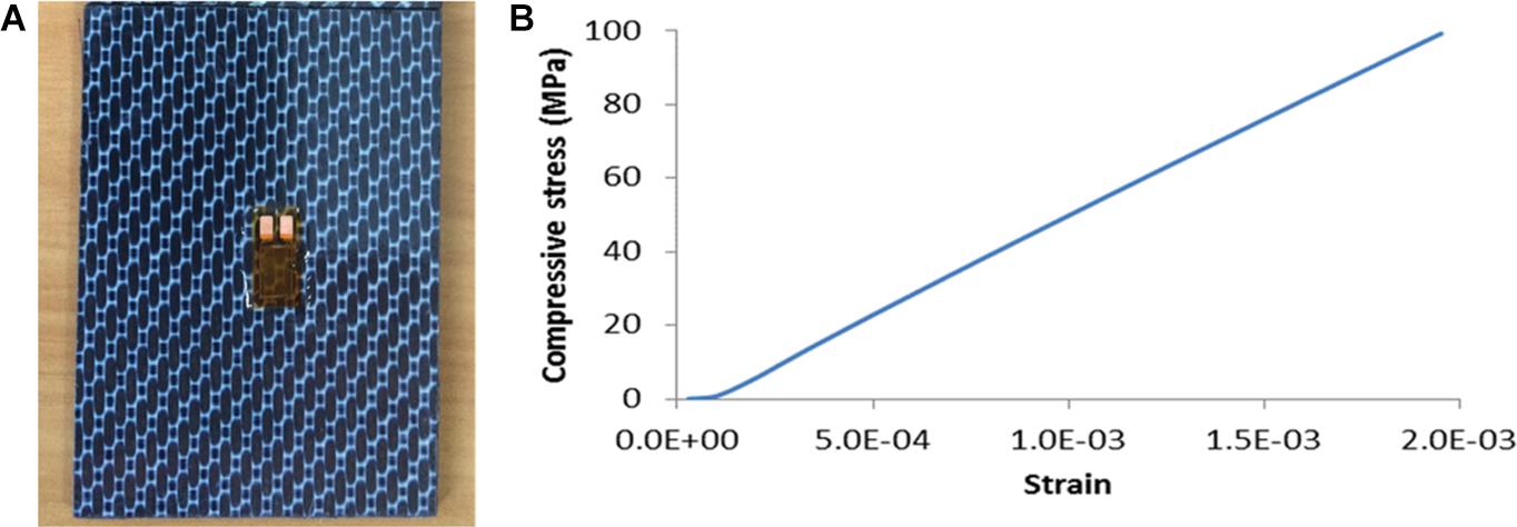
Figure 7. (A) Laminate used for stringers (external ply at 0°/90°). (B) Results of the test on the laminate used for stringers.
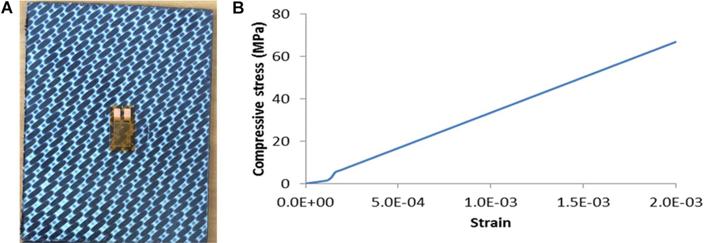
Figure 8. (A) Laminate used for the panel. (external ply at +45°/−45°). (B) Test on the laminate used for the panel.
Analytical and Numerical Analysis of Buckling
L-Shaped Stringers
The global buckling load of an Euler beam in clamped–clamped conditions is provided by the Eulerian theory that in the elastic field assumes the following form:
where Pcr is the critical load, E is the elastic modulus, I is the minimum inertia moment respect to an axis in the beam section plane, and le is the beam effective length. Equation 1 requires that it is verified that the beam stress falls in the elastic region behavior of the material. If this is not true, correction should be applied to the theory (tangent modulus theory) in order to include in the buckling load the non-linear effects of the material (Rivello, 1969; Megson, 2016).
According to Eq. 1, the first buckling load is approximately 66,150 N, considering clamping conditions at both the edges of the beam. If the assumed constraint conditions would be of the type simply supported, the critical load would be one-fourth of the previously calculated (16,540 N). It is reasonable to have both these figures in mind since, often, the boundary conditions are not perfectly and precisely defined or, in other terms, they cannot be described uniquely. If these loads would be actually the critical ones, the related stress over the beam section would be 555 or 139 MPa, respectively. The calculated compressive stress, in clamping conditions, is apparently higher than the measured yielding stress and can fall in the pseudo-plastic region. This would require a correction of Eq. 1 including the material non-linear effects in the beam bending and a preliminary proper experimental investigation on the stress/strain curve of the material until the failure. Since previous considerations refer to global instability of the stringer, before performing further material tests for getting the stress/strain curve up to break, other buckling mechanisms should be explored. As mentioned before local instability was very likely to occur for the thin flanges of which the stringer was made and a proper investigation on such possibility was needed mainly after the previous analytical computations from the beam theory. Therefore, the two separates buckling loads for these two thin plates were evaluated with proper constraints conditions to have exact figures of the local instability loads. The buckling stress of a thin flat plate is provided by the following equation (Rivello, 1969; Megson, 2016):
where σCR is the critical stress in the plate, k is the buckling coefficient depending on the plate geometry and boundary conditions, t the plate thickness, and b the length of the loaded side.
Equation 2 indicates that the first buckling stresses of the two flanges forming the stringers are:
These results, much lower than that corresponding to global buckling above reported, confirm that local instability is likely to occur before the global one: the beam does not buckle as a whole but as an assembly of plates. More precisely, the following buckling mechanism can be imagined for the L-shaped stringer: in the first part of the test, both the flanges contribute to the compressive load absorption until the average stress over the beam section is equal to 44 MPa (that corresponds to an external applied load of about 5220 N). At this point, the flange 2 (the longer one in Figure 1) buckles and it is reasonable to assume that, from that value of the applied load and above, flange 2is not able to carry any further additional load. Incremental loads are therefore born only by flange 1 that will buckle when the stress on its section reaches 85 MPa. Making simple computations, the applied compressive load corresponding to the conditions that both the flanges are in buckling is about 7438 N that is reasonably close to the experimental value. This value is slightly underestimated since the assumption that the flange 2 does not carry any further additional load does not correspond to the real behavior. A confirmation of the validity of such buckling mechanism was provided by the analysis of the strain measured by the strain gauges on stringers that confirmed the presence of buckles on the two flanges at the previous mentioned loads.
Finite-element analysis (FEA) was carried out on the stringer using Patran/Nastran commercial software. SOL105 (linear buckling analysis) was performed in order to evaluate the first buckling loads and modes. CQUAD4 elements of the Nastran library were used for simulating the structure. The adopted constraints were fixed nodes at each end of the stringer to reproduce the boundary conditions during the test (Figure 9).
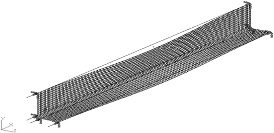
Figure 9. First buckling mode of the stringer in linear analysis.
The first buckling load provided by the linear numerical analysis was 7400 N and the buckling mode involved both the two flanges of the stringer. Non-linear static analyses (SOL106), taking into account the large deformations of the structure under the action of compressive load, were performed in order to better reproduce the test and to evaluate the buckling and post-buckling behavior of the stringer. Non-linear analysis (SOL106) provides results similar to the linear buckling analysis (SOL105): the lateral displacement, i.e., normal to the stringer longitudinal axis, shown in Figure 10 diverges when the buckling load is reached, as expected. Two different boundary conditions were simulated, simple supports and fixed supports at the edges, being higher the buckling load when the latter ones were adopted. As shown in Figure 10, the deflection diverges under clamped constraints when the external load slightly exceeds 8000 N, while for the simple supports condition, when the load exceeds 5000 N. In the former case, the result is very close to the average measured buckling load at 8030+210 N (Figure 3).
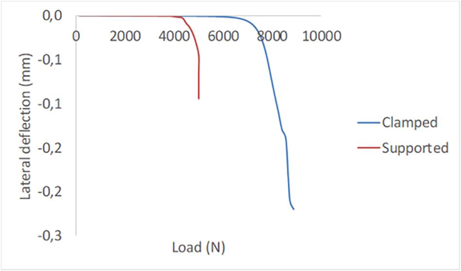
Figure 10. Non-linear static analyses of the stringer: load–lateral deflection curve.
Stiffened Panel
The results of the compression test on the stiffened panel were compared with the results of the FEA carried out with Ansys 2019 R1. Linear modal analysis was performed on the stiffened panel using the properties obtained by testing of the two different laminates used for the L-shaped stringers and the flat panel, above reported. Linear buckling analysis (also called eigenvalue buckling analysis) predicts the theoretical buckling strength of an ideal elastic structure. A mesh of 16,400 shell elements and 17,069 nodes was used for simulating the stiffened panel. The stringers were considered merged to the base plate. A first local buckling mode, occurring at the unrestrained edges of the base plate was obtained when the applied load reached 10,542 N (Figure 11), showing a good agreement either with the first slope change reported in Figure 5 either with the shape of the panel shown in Figure 4. The panel is a structure with high modal density so many different eigenvalues corresponding to the buckling loads and eigenvectors corresponding to buckled deformed shapes can be identified in a small load range. For sake of brevity here, it is not reported the list of all buckling loads due to local instabilities, before a global buckling load, involving all the structural members of the panel, was attained. The unstable shape of the panel, obtained at a buckling load of 53,500 N, reported in Figure 12, corresponds to the eigenvalue number 33 provided by the buckling analysis. This load is very close to the one observed at the plateau in Figure 5, where load jumps are associated to the development of first cracks in the stringers. Furthermore, the deformed shape gives a clear evidence of how the central part of the panel bends out of the base plate under the action of the compressive load and how the central stiffeners bends in a plane orthogonal to the base plate. A close agreement between the observed failure of stringers reported in Figure 5 with the prediction of high strains (and consequently stresses) at the free flange of the stringers must be highlighted.
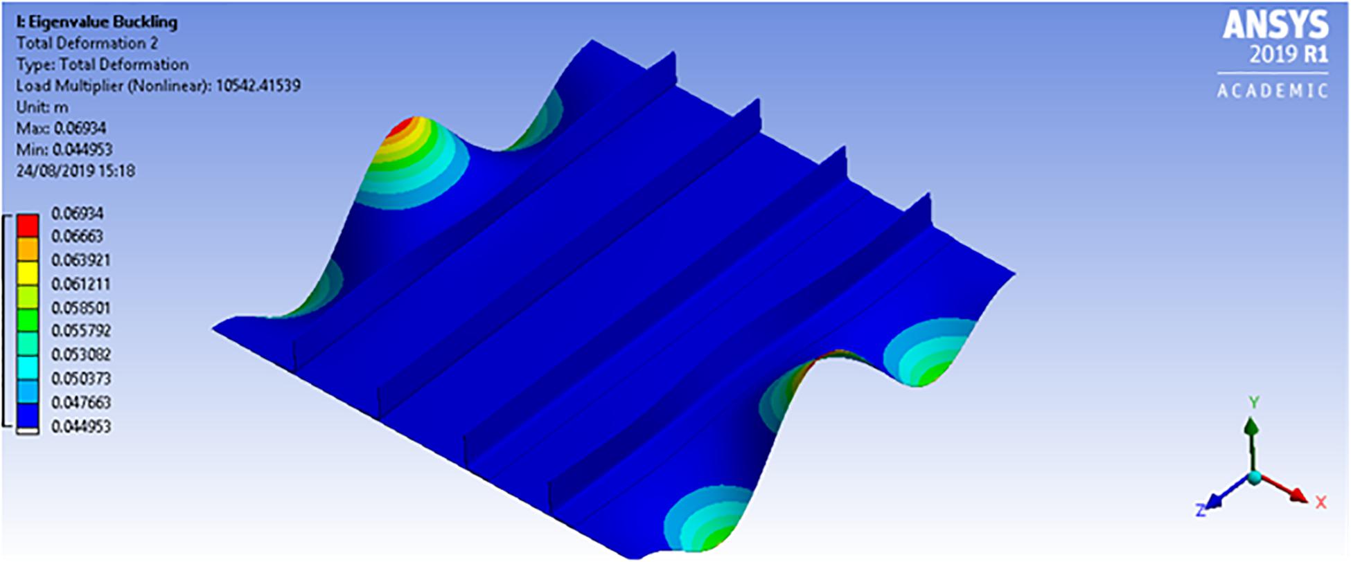
Figure 11. Stiffened panel FE model: first local instability load.
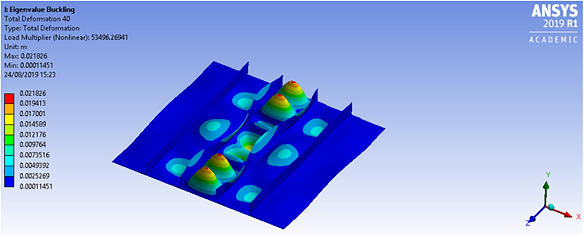
Figure 12. FE model buckling results: first global instability load.
A possible improvement of the performances under compression loads of the stiffened panel was studied. An alternative geometry the stringers, changing the section from L-shaped to C-shaped (Figure 13), was considered. The results of FE buckling analysis obtained with this modified panel are reported in Table 2.
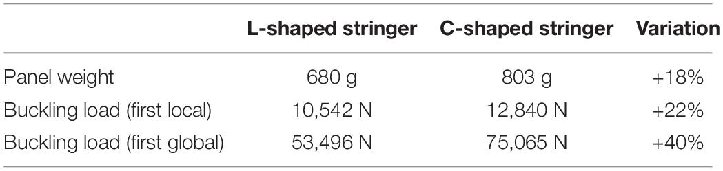
Table 2. Effect of shape modification of the stringer.
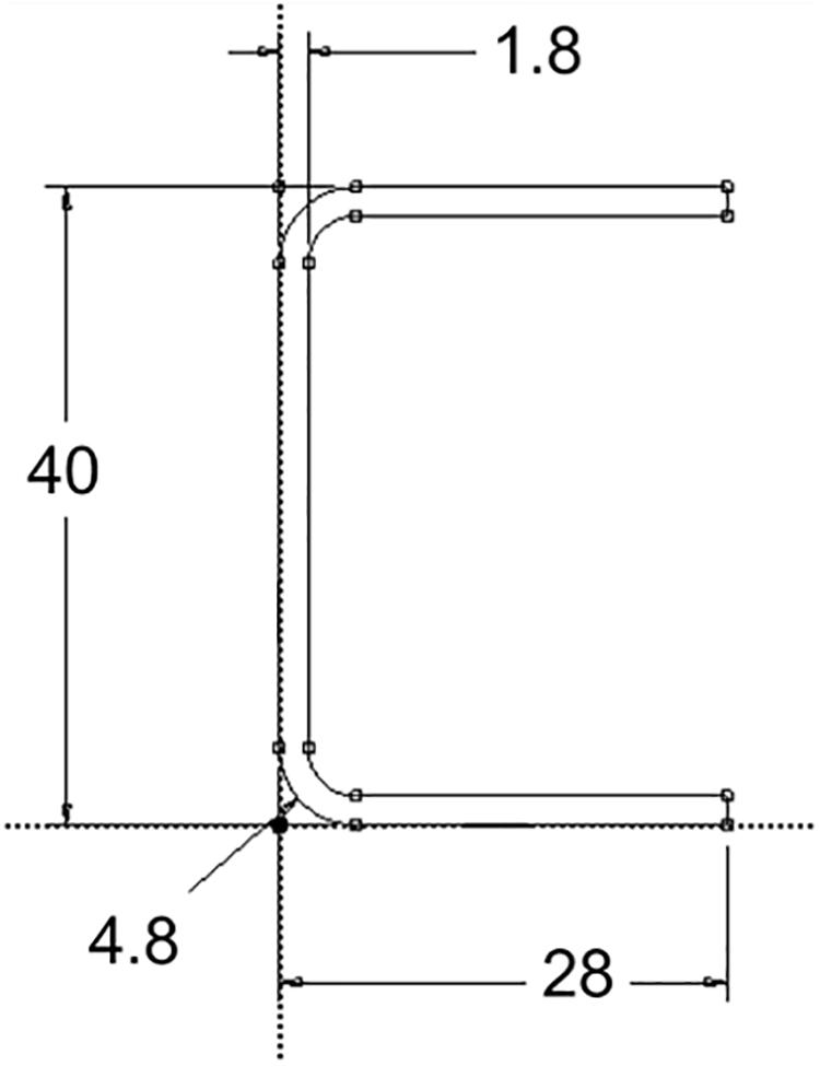
Figure 13. C-shaped stringer.
The proposed modification of the stringers shape led to an increase of the panel weight equal to 18% but associated with 40% higher first global buckling load. Although in aeronautical design modifications leading to weight increase are strongly undesired these results give a clear idea of how sensitive is the buckling load to the stiffener shape and which is the impact of geometric optimization on mechanical performances and weight.
Relevance of Results in the Design of Aeronautic Structures
The first main finding of this work is the excellent post-buckling behavior of the PPS/carbon laminates as resulting from the compression tests performed on both the L-shaped stringer and the stiffened panel. This is very important for aeronautical structures to which the certification agencies impose specific operational restrictions. More precisely, the regulatory framework demands that the primary structures at the limit loads, that are the maximum loads acting on the airplane in operation, work in the elastic field. In addition, the regulations demand that at the ultimate loads, that are the limit loads multiplied by 1.5 (safety factor), primary structures must be able to withstand these loads for at least 3 s before any catastrophic collapse. It is common that an aircraft primary structure does not collapse for material failure but for structural instability.
Therefore, if the material exhibits a hyper-elastic behavior, the real margin existing between the yielding stress and the structural collapse of the component is relevant. In the case of these thermoplastic matrix composites with high post-buckling capability, such a margin turns in an actual safety factor much higher than the nominal one equal to 1.5. Taking this concept to its extreme consequences, the designer could also conceive the structure operating in the flight envelope at the limit of the conditions of structural instability, keeping in mind that no permanent deformations are allowed inside it. On the other hand, some recent development looking at future aircrafts is exploring solutions exploiting local structural instabilities for aircraft specific operational purposes (such as the morphing solutions reported in Gano et al., 2003; Ursache et al., 2004; Barrett et al., 2005; Vos et al., 2007; Phani et al., 2008; Kuder et al., 2013).
Relevance of Results in the Design of Aeronautic Structures
The first main finding of this work is the excellent post-buckling behavior of the PPS/carbon laminates as resulting from the compression tests performed on both the L-shaped stringer and the stiffened panel. This is very important for aeronautical structures to which the certification agencies impose specific operational restrictions. More precisely, the regulatory framework demands that the primary structures at the limit loads, that are the maximum loads acting on the airplane in operation, work in the elastic field. In addition, the regulations demand that at the ultimate loads, that are the limit loads multiplied by 1.5 (safety factor), primary structures must be able to withstand these loads for at least 3 s before any catastrophic collapse. It is common that an aircraft primary structure does not collapse for material failure but for structural instability. Therefore, if the material exhibits a hyper-elastic behavior, the real margin existing between the yielding stress and the structural collapse of the component is relevant. In the case of these thermoplastic matrix composites with high post-buckling capability, such a margin turns in an actual safety factor much higher than the nominal one equal to 1.5. Taking this concept to its extreme consequences, the designer could also conceive the structure operating in the flight envelope at the limit of the conditions of structural instability, keeping in mind that no permanent deformations are allowed inside it. On the other hand, some recent researches related to the future aircrafts are exploring solutions exploiting local structural instabilities for aircraft specific operational purposes (i.e., morphing solutions reported in Gano et al., 2003; Ursache et al., 2004; Barrett et al., 2005; Vos et al., 2007; Phani et al., 2008; Kuder et al., 2013).
A second relevant finding indeed is that the induction welding technique was highly efficient. Not a single stringer was visibly detached from the panel at the end of the test even after non-destructive inspection of welded surfaces.
Conclusion
Buckling and post-buckling behavior of induction welded thermoplastic matrix composites for aerospace application was the main subject of this study. Two structural components were tested in compression until the ultimate load was reached: L-shaped thermoplastic stringers and a flat panel reinforced with four of these L-shaped stringers. The L-shaped stringers showed a good structural behavior being able to take incremental loads after the first buckling appeared. The tests on the stiffened panel demonstrated that induction welding was effective until the structural ultimate load and no debonding was detected at the interface between the stringers and the panel. The FEA provided, indeed, buckling loads in good agreement with the experimental ones, taking into account either the geometric non-linearities associated with the large deformations of the structures under compressive loads either the buckling of the flanges composing the stringer. It is also worthwhile to remark how the simple analytical models were able to capture the essence of complex buckling mechanisms like the local instability of the L-shaped stringer. However, in order to capture the post-buckling behavior of stiffened panels, more complex theories and models taking into account both geometric and materials non-linearity are needed (Barbero et al., 2014; Mania et al., 2017). The proposed approach can be used for similar structures, i.e., a deeper understanding of the phenomena leading to collapse of the stiffened panel results from testing under compression loads first the stiffening elements of the panel and then the whole panel. Furthermore, the test on L-shaped stringers and the panel indicated that for complex structures it is necessary to consider the local buckling of single elements.
Data Availability Statement
The datasets generated for this study are available on request to the corresponding author.
Author Contributions
GS performed the numerical analysis, participated to buckling experiments of stringers, and contributed to data analysis and manuscript writing. SP made the samples, designed and performed the experiments, and contributed to data analysis. GB made the samples, designed and performed the experiments, and contributed to data analysis. AM participated to experimental activities, to the manuscript writing, and to the analysis of the experimental and numerical results.
Conflict of Interest
The authors declare that the research was conducted in the absence of any commercial or financial relationships that could be construed as a potential conflict of interest.
References
Barbero, E. J., Madeo, A., Zagari, G., Zinno, R., and Zucco, G. (2014). Koiter asymptotic analysis of folded laminated composite plates. Compos. B Eng. 61, 267–274. doi: 10.1016/j.compositesb.2014.01.045
Barrett, R., McMurtry, R., Vos, R., Tiso, P., and Breuker, R. D. (2005). “Post-buckled precompressed (PBP) elements: a new class of flight control actuators enhancing high-speed autonomous VTOL MAVs,” in Proceedings of SPIE 5762, Smart Structures and Materials 2005: Industrial and Commercial Applications of Smart Structures Technologies, ed. E. V. White (Washington, DC: SPIE), 111–122. doi: 10.1117/12.599083
da Costa, A. P., Botelho, E. C., Costa, M. L., Narita, N. E., and Tarpani, J. R. (2012). A review of welding technologies for thermoplastic composites in aerospace applications. J. Aerosp. Technol. Manag. 4, 255–266. doi: 10.5028/jatm.2012.040303912
Encinas, N., Oakley, B. R., Belcher, M. A., Blohowiak, K. Y., Dillingham, R. G., Abenojar, J., et al (2014). Surface modification of aircraft used composites for adhesive bonding. Int. J. Adhes. Adhes. 50, 157–163. doi: 10.1098/rsos.171272
Erber, A., and Spitko, S. (2014). Expanded role for thermoplastic composites. Reinforced Plast. 58, 29–33. doi: 10.1016/S0034-3617(14)70178-X
Gano, S. E., Renaud, J. E., Batill, S. M., and Tovar, A. (2003). “Shape optimization for conforming airfoils,” in Proceedings of the 44th AIAA/ASME/ASCE/AHS Structures, Structural Dynamics, and Materials Conference, 7–10, 2003, (Norfolk, VA: American Institute of Aeronautics and Astronautics). doi: 10.2514/6.2003-1579
Kong, C.-W., Lee, I.-C., Kim, C.-G., and Hong, C.-S. (1998). Postbuckling and failure of stiffened composite panels under axialcompression. Compos. Struct. 42, 13–21. doi: 10.1016/S0263-8223(98)00044-0
Kuder, I. K., Arrieta, A. F., Raither, W. E., and Ermanni, P. (2013). Variable stiffness material and structural concepts for morphing applications. Prog. Aerosp. Sci. 63, 33–55. doi: 10.1016/j.paerosci.2013.07.001
Loos, A. C., Springer, G. S., Sanders, B. A., and Tung, R. W. (1980). Moisture absorption of polyester-E glass composites. J. Compos. Mater. 14, 142–154. doi: 10.1177/002199838001400206
Maffezzoli, A. M., Kenny, J. M., and Nicolais, L. (1989). Welding of PEEK/carbon fiber composite laminates”. SAMPE J. 25, 35–40.
Mallick, P. K. (2007). Fiber-Reinforced Composites: Materials, Manufacturing, and Design. Boca Raton, FL: CRC press. doi: 10.1201/9781420005981
Mania, R. J., Madeo, A., Zucco, G., and Kubiak, T. (2017). Imperfection sensitivity of post-buckling of FML channel section column. Thin Walled Struct. 114, 32–38. doi: 10.1016/j.tws.2017.01.033
Mathijsen, D. (2016). Leading the way in thermoplastic composites. Reinforced Plast. 60, 405–407. doi: 10.1039/c6nr02216b
Megson, T. H. G. (2016). Aircraft Structures for Engineering Students. Oxford: Butterworth-Heinemann.
Mo, Y., Ge, D., and He, B. (2016). Experiment and optimization of the hat-stringer-stiffened compositepanels under axial compression. Composites B 84, 285–293. doi: 10.1016/j.compositesb.2015.08.039
Mouzakis, D. E., Zoga, H., and Galiotis, C. (2008). Accelerated environmental ageing study of polyester/glass fiber reinforced composites (GFRPCs). Compos. B: Eng. 39, 467–475. doi: 10.1016/j.compositesb.2006.10.004
Nishida, H., Carvelli, V., Fujii, T., and Okubo, K. (2018). Thermoplastic vs. thermoset epoxy carbon textile composites. IOP Conf. Ser Mater. Sci. Eng. 406:012043. doi: 10.3390/ma10030293
Offringa, A. (2005). Thermoplastics in aerospace, new products through innovative technology. SAMPE J. 41, 19–27.
Pappadà, S., Salomi, A., Montanaro, J., Passaro, A., Caruso, A., and Maffezzoli, A. (2015). Fabrication of a thermoplastic matrix composite stiffened panel by induction welding. Aerosp. Sci. Technol. 43, 314–320. doi: 10.1016/j.ast.2015.03.013
Perret, A., Mistou, S., Fazzini, M., and Brault, R. (2012). Global behaviour of a composite stiffened panel in buckling: experimental investigation. Compos. Struct. 94, 376–385. doi: 10.1016/j.compstruct.2011.07.029
Phani, A. S., Butler, R., Habgood, S., and Bowen, C. R. (2008). “Analysis of wing morphing via frame buckling,” in Proceedings of 49th AIAA/ASME/ASCE/AHS/ASC Structures, Structural Dynamics and Materials Conference, 07.04.2008-10.04.2008, (Schaumburg, IL: American Institute of Aeronautics and Astronautics). doi: 10.2514/6.2008-1792
Scarselli, G., Castorini, E., Panella, W., Nobile, R., and Maffezzoli, A. (2015). Structural behaviour modelling of bolted joints in composite laminates subjected to cyclic loading. Aerosp. Sci. Technol. 43, 89–95. doi: 10.1016/j.ast.2015.02.017
Sun, X. C., Kawashita, L. F., Kaddour, A. S., Hiley, M. J., and Hallett, S. R. (2018). Comparison of low velocity impact modelling techniques for thermoplastic and thermoset polymer composites. Compos. Struct. 203, 659–671. doi: 10.1016/j.compstruct.2018.07.054
Ursache, N. M., Bressloff, N. W., and Keane, A. J. (2004). “The design of post-buckled spinal structures for airfoil shape control using optimization methods,” in Proceedings of the 5th ASMO UK/ISSMO Conference on Engineering Design Optimization, eds O. M. Querin, P. D. Gosling, J. Sienz, and V. V. Toropov (Leeds: ASMO-UK).
Vieille, B., Casado, V. M., and Bouvet, C. (2013). About the impact behavior of woven-ply carbon fiber-reinforced thermoplastic- and thermosetting-composites: a comparative study. Compos. Struct. 101, 9–21. doi: 10.1016/j.compstruct.2013.01.025
Vos, R., Barrett, R., deBreuker, R., and Tiso, P. (2007). Post-buckled precompressed elements: a new class of control actuators for morphing wing UAVs. Smart Mater. Struct. 16, 919–926. doi: 10.1088/0964-1726/16/3/042
Wang, Y., and Hahn, T. H. (2007). AFM characterization of the interfacial properties of carbon fiber reinforced polymer composites subjected to hygrothermal treatments. Compos. Sci. Technol. 67, 92–101. doi: 10.21614/chirurgia.112.1.25
Yousefpour, A., Hojjati, M., and Immarigeon, J.-P. (2004). Fusion bonding/welding of thermoplastic composites. J. Thermoplas. Compos. Mater. 17, 303–341. doi: 10.3390/ma13071634
Keywords: buckling, induction welding, FEM analysis, poly-phenylene sulfide composites, stiffened aircraft wing panel
Citation: Scarselli G, Pappadà S, Buccoliero G and Maffezzoli A (2020) Buckling Behavior of Poly-Phenylene-Sulfide/Carbon L-Shaped Stringers and a Stiffened Panel Obtained by Induction Welding. Front. Mater. 7:107. doi: 10.3389/fmats.2020.00107
Received: 12 September 2019; Accepted: 07 April 2020;
Published: 06 May 2020.
Edited by:
Andrea Dorigato, University of Trento, ItalyReviewed by:
Liqing Wei, United States Forest Service (USDA), United StatesPhilippe Boisse, Institut National des Sciences Appliquées de Lyon (INSA Lyon), France
Copyright © 2020 Scarselli, Pappadà, Buccoliero and Maffezzoli. This is an open-access article distributed under the terms of the Creative Commons Attribution License (CC BY). The use, distribution or reproduction in other forums is permitted, provided the original author(s) and the copyright owner(s) are credited and that the original publication in this journal is cited, in accordance with accepted academic practice. No use, distribution or reproduction is permitted which does not comply with these terms.
*Correspondence: Alfonso Maffezzoli, alfonso.maffezzoli@unisalento.it