Studies on Stress Corrosion Cracking of Vit 105 Bulk Metallic Glass
 Annett Gebert1*
  David Geissler1
  Stefan Pilz1 Margitta Uhlemann1 Farnaz A. Davani2
  Sven Hilke2
  Harald Rösner2
  Gerhard Wilde2
- 1Institute for Complex Materials, Leibniz IFW Dresden, Dresden, Germany
- 2Institut für Materialphysik, Westfälische Wilhelms-Universität Münster, Münster, Germany
The project “Stress Corrosion Cracking of Zr-based Bulk Metallic Glasses” (SCC of Zr-BMGs) within PP1594 mainly dealt with mechanical–corrosive interactions and failure of this class of metastable materials. It focused on one of the most application-relevant zirconium (Zr)-BMG, Vit(reloy) 105, with composition Zr52.5Cu17.9Ni14.6Al10Ti5 (at.%). Even though this BMG is known as an extraordinary glass former, the metallurgical processing is still a critical issue. In contrast to conventional processing, i.e., arc melting of master alloy ingots from single constituents, a different route using binary pre-alloys for the master alloys production was applied and led to superior mechanical properties upon mechanical testing under tensile and three-point-bending (3PB) conditions in air. As a reference and for a detailed understanding of failure, fracture, and cracking of Zr-based BMG in air, notched specimen 3PB experiments with in situ microscopic observation were done and the still controversial interpretation of the mechanical behavior of BMG in the framework of fracture mechanics was addressed. The specimen from the in situ 3PB tests served for transmission electron microscopy (TEM) investigations on the structural nature of shear bands in BMG on the atomistic scale. Altogether, complete crack paths could be observed and analyzed, and based on this, details of the shear band-driven crack growth are described. While in first SCC studies using a newly developed setup full cross section (3PB) bars were investigated, in recent in situ experiments, notched specimens were tested in 0.01 M NaCl, yielding strong evidence for a catastrophic failure due to hydrogen embrittlement (HE). The known susceptibility to pitting corrosion in halide-containing environments is only the initial stage for failure under SCC conditions. Once pitting is initiated, the local electrode potential is severely reduced. Further, the hydrolysis reaction of oxidized Zr4+ to zirconyl ions ZrO2+ during local BMG dissolution produces H+ and, thus, a local acidic environment that enables proton reduction and hydrogen absorption in the stressed BMG region. The peculiar failure and fracture surface characteristics as well as the proven local reduction of the pH value in the vicinity of the notch during in situ experiments clearly account for the proposed HE-SCC failure mechanism.
Introduction
Among the bulk metallic glass (BMG)-forming systems, multicomponent zirconium (Zr)-based alloys are most prominent and best investigated regarding glass formation, mechanical performance, and chemical reactivity. Impressive mechanical properties of those alloys, like Zr55Cu30Al10Ni5, Zr57Cu15.4Ni12.6Al10Nb5 (Vit 106), Zr41.2Ti13.8Cu12.5Ni10Be22.5 (Vit 1), and Zr52.5Cu17.9Ni14.6Al10Ti5 (Vit 105), are comparatively very high fracture strength values of 1,400–1,900 MPa, Young’s modulus values of 70–96 GPa, and typical ≤2% elongation at yielding. These alloys have been mostly employed in fundamental studies of the deformation behavior of metallic glasses and basic mechanisms comprising processes of shear band nucleation and propagation were described. This knowledge is used for new strategies toward enhanced mechanical properties (Cheng et al., 2008; Trexler and Thadhani, 2010; Suryanarayana and Inoue, 2011). Optimization of casting techniques (Suryanarayana and Inoue, 2011; Yokoyama, 2015) and new concepts for additive manufacturing (Deng et al., 2019) allow for the fabrication of BMGs with larger dimensions or with complex shapes. This has opened the door for commercial production of those BMGs and for prospective engineering applications, e.g., hardware casings, sportive goods, watches and jewelry, and biomedical products (Suryanarayana and Inoue, 2011). Nevertheless, questions regarding long-term durability under application-relevant conditions, i.e., the superposition of mechanical loading and (often humid) environment remained scarcely addressed so far. With our fundamental studies on fracture toughness and on stress corrosion phenomena, we contribute to the understanding of failure mechanisms of this innovative class of glass-forming alloys.
Bulk metallic glasses are ideally single-phase, i.e., theoretically, they do not contain structural or chemical defects. This is alike the basic characteristics of inorganic glasses. Their composition is often complex and atypical in comparison to conventional crystalline alloys. (B) MGs have unique short- and medium-range order (SRO/MRO) structures, their topology yields outstanding properties and determines their response to mechanical load (Wondraczek et al., 2011). For example, synchrotron diffraction studies and computational analyses of the atomistic structure and stress effects of Zr-Cu(-Al) glasses revealed that their SRO has interpenetrating icosahedral-like clusters forming superclusters. Under tensile or compressive deformation, the topological and chemical SRO change results in dynamic cluster-destruction-recreation processes and reorganization of superclusters (Almyras et al., 2010; Zhang et al., 2011; Lekka et al., 2012).
Metallic glasses are basically expected to show “ideal brittle fracture” performance due to the absence of strain hardening and barriers for crack propagation. Their structural nature cannot yield the conditions to reduce high stress levels in the regions of crack tips. Such an ideal brittle behavior must result in a lack of plastic deformation and in very low toughness (Schuh et al., 2007). Nevertheless, Lewandowski et al. (2005) derived – also based on empirical data – critical levels for the Poisson’s ratio ν, and this classifies BMGs according to a certain glass toughness. Hence, cast Zr-based glasses are comparatively “tough”; they show local plasticity due to multiple shear band formation. Together with high strength, this results in a significant fracture toughness.
Fracture toughness and fatigue resistance of glass-forming alloys have to be critically assessed, but they are far from being comprehensively understood (Schuh et al., 2007). Only for selected Zr-based BMG studies on these issues have been conducted. Firstly, Gilbert et al. (1997) determined for amorphous Zr41.2Ti13.8Cu12.5Ni10Be22.5 CT-specimens a fracture toughness of KIc ∼55 MPa√m which is comparable to that of a high-strength steel. Under cyclic loading, fatigue crack growth rates comparable to those of ductile crystalline alloys were determined. Flores and Dauskardt (1999) fundamentally analyzed fatigue pre-cracked, single-edge notched tension samples of this BMG. In situ microscopic observations under tensile loading conditions revealed remarkable plastic deformation in crack tip regions which is indicative for high facture toughness. The local generation of shear bands and the branching of cracks cause an energy-dissipating region, and this determines crack growth. Recently, Madge (2015) reviewed the current state of research regarding toughness of BMGs and emphasized that even less tough metallic glasses are tougher than oxide glasses. But already among Zr-based glasses, a wide variability in fracture toughness and fatigue resistance data was evidenced, which is obviously related to the capability of the glass specimen to form a shear banding zone at a crack tip region. This is determined by experimental conditions (e.g., notch dimension, type of experiment, sample size) but is also strongly correlated with the alloy chemistry. Kruzic (2011) assessed the parameters which can affect the fracture and fatigue behavior of BMGs. The glass composition determining the SRO/MRO, the structural relaxation state (residual stress state), and the nature of surface and bulk defects are main important factors. Moreover, a high sensitivity for environmental influences, i.e., the test medium, was emphasized.
Owing to their ideally single-phase chemically homogeneous nature, metallic glasses are often considered as highly corrosion-resistant materials. Indeed, Zr-Cu-based BMGs can exhibit excellent passivity in a wide pH value range which is due to their valve-metal components Zr, Ti, Nb, or Al. However, in chloride-containing media, they are prone to pitting corrosion with low re-passivation ability. Our studies revealed that this has to be attributed to their high Cu content and selective constituent dissolution (Gostin et al., 2015a). Further, chemical and morphological defects determine the pitting susceptibility of BMG specimens which were fabricated under actual conditions (Scully et al., 2007). We also demonstrated that corrosive reactions interact with mechanically induced defects like shear bands (Gebert et al., 2012). It was predictable that those phenomena will be strongly accelerated under crevice-like conditions, i.e., in a crack tip zone. On the other hand, in our project, an approach for exploiting those mechano-corrosive interactions for the in situ electrochemical analysis of deformation processes was developed (Grell et al., 2015). When a quasi-static mechanical test is conducted in an inert salt solution with the BMG sample as an electrode, early stages of plastic deformation can be detected via its electrochemical response which is much more sensitive than the macroscopic mechanical signal. The generation of first shear bands is accompanied by a local breakdown of the passive film at the BMG surface, yielding characteristic discontinuous changes of the electrode potential. There is a great potential for further developing this method.
Meanwhile, more and more studies are published which emphasize the high sensitivity of Zr-based BMGs for stress corrosion cracking (SCC) and corrosion fatigue (CF) phenomena. We have summarized those in a recent review (Gostin et al., 2015b). Pit formation is the typical first step, and in the following, cracks are initiated at those surface defects. A rapid crack growth is mostly ascribed to active dissolution in the region of the crack tip. Also, a few studies claim hydrogen damage to be responsible for crack propagation. Zr-based BMGs are excellent hydrogen absorbers. Investigations on pre-charged samples showed that hydrogen influences the shear band formation at notches and reduces the limit of the intensity factor. Upon continuous or cyclic loading, hydrogen inhibits the crack growth. Altogether, the complex SCC and CF mechanisms in Zr-based BMGs are by far not understood and have to be considered – similar to crystalline metals – from the viewpoint of both, metal dissolution and hydrogen-related effects as driving force for crack propagation and material failure. So far, due to the limited availability of appropriate glassy sample sizes and comparatively fast crack propagation rates, SCC and CF testing of BMGs was often not possible according to ASTM/DIN standard testing conditions. New setups and protocols have to be developed, enabling the analysis of those complex damage processes for smaller sample dimensions to clarify the impact of BMG alloy chemistry and particular structural states.
The present paper reviews highlight results of the SCC of Zr-BMG project starting with effects of different casting routes for BMG fabrication on their basic mechanical performance under tensile and 3PB conditions via in situ analysis of shear band-driven crack propagation upon 3PB in air up to SCC analyses with (un)/notched 3PB specimen under potential control in chloride-containing electrolytes. For these studies, the Zr52.5Cu17.9Ni14.6Al10Ti5 (VIT 105) alloy was chosen as an example since it is well known as one of the best glass formers among the Zr-based alloys and one with highest application potential.
Materials and Methods
Bulk Metallic Glass Sample Preparation
As many studies have already shown (Gebert et al., 2012; Yokoyama, 2015), element purity as well as melting and casting conditions are extremely decisive factors determining the quality of BMG samples in terms of achieving single-phase chemically homogeneous glassy states. In order to address this issue, we employed two different arc melting routes for Zr52.5Cu17.9Ni14.6Al10Ti5 (Vit 105) ingot production:
Route (A) This follows the common procedure for BMG preparation. An appropriate mixture of single constituent elements Zr, Cu, Ni, Al, and Ti with very high purity (purity ≥99.9%) was used for arc melting on a Cu hearth under highly purified Ti-gettered Ar atmosphere. To ensure a homogeneous chemical composition, the ingots with a mass of 20 g were re-melted at least three times (Gostin et al., 2015c).
But large differences of the temperatures of melting varying from 933.5 K (Al) to 2,125 K (Zr) cause difficulties to obtain homogeneous master alloys. Therefore, a new procedure was established:
Route (B) This route is based on four binary pre-alloys in appropriate compositions which were prepared separately and used as starting material. The final Zr52.5Cu17.9Ni14.6Al10Ti5 master alloy was re-melted in several steps for homogenization. All details of the process are provided in Geissler et al. (2019).
Then, flat BMG specimens (3 mm × 10 mm × 85 mm size) were cast using the master alloy ingots by means of suction casting into a copper mold. Resulting sample types are nominated as “A” and “B.”
Material Characterization
The cast plates were chemically analyzed by inductively coupled plasma-optical emission spectrometry (ICP-OES) (SPECTRO ARCOS MV). For these samples, an approximate weight of 150 mg was taken from three different sections of one plate (top, center, bottom). The relative standard deviation (RSD) represents the error of the measurement and the homogeneity of material. It results from four times repeated measurements of three parallel weights of about 50 mg. Further, carrier gas hot extraction was employed to determine the impurity level, especially the oxygen concentration (LECO TC-436DR). The freshly etched samples which were taken from the different sections of a plate were mixed, and from that, average values of three repeated measurements were determined. The structure of BMG plates was investigated by X-ray diffraction (XRD) with a Philips Panalytical X’PERT-Pro MPD system with Co-Kα radiation in Bragg-Brentano geometry with theta–theta focusing. The thermal behavior was studied by differential scanning calorimetry (DSC) using a PerkinElmer DSC Diamond at 40 K/min under Ar. Polished as well as fractured surfaces were investigated by scanning electron microscopy (SEM) with a Leo 1530 Field Emission Gun SEM with Zeiss Gemini column operated at 20 kV. Microstructural investigations [transmission electron microscopy (TEM)] were performed using a Thermo Fisher Scientific FEI Themis 300 G3 transmission electron microscope. A more detailed description for the experimental setup is given by Hilke et al. (2019).
In situ Analysis of Cracking in Air
For in situ observation of fracture and failure in air, three-point-bending (3PB) tests were conducted using a Kammrath & Weiss Tensile-Compressive testing device equipped with an in-house developed 3PB kit as illustrated in Figure 1A. For these tests notched bars were employed. To fit to the used outer support span of S = 18 mm, the cast BMG plates were cut into bars with appropriate size and with a geometry that is close to recommendations of ASTM E399, E1820, ISO12135, cf. SEN(B) specimen (Geissler et al., 2018). Each side of a pre-cut slug beam was prepared to the desired size by standard metallographic procedures (Geissler et al., 2019). The final outer geometry of a sample was S < L = 20.5 mm, W = 4.33 mm, and B = 2.243 mm. A chevron edge notch was introduced in the middle of the bending bar by electrodischarge machining that was finally sharpened by a razor blade. The 3PB test was monitored and recorded in situ with a microDAC strain measurement device (Chemnitzer Werkstoffmechanik GmbH). A 5-kN load cell was used for the load measurement during the experiment. Further details are given in Geissler et al. (2019). In addition, tensile tests were done using the same Kammrath & Weiss Tensile-Compressive Testing device. The developed tensile testing setup for small-sized samples in Dogbone geometry was used. From cast BMG plates, appropriate sample dimensions were obtained by means of electrodischarge machining. The sample surface preparation was performed by standard metallographic procedures. The final sample had a thickness of about 1 mm, a gauge length of 5 mm, and a width of about 1 mm. Sample and fracture surfaces were as well analyzed by (SEM).
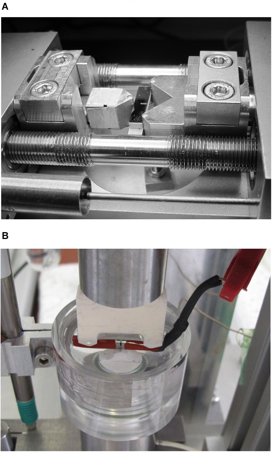
Figure 1. (A) Three-point-bending (3PB) test in air with notched Vit 105 bulk metallic glass (BMG) sample in a Kammrath &Weiss tensile-compressive testing device with 3PB kit and (B) setup for 3PB-stress corrosion cracking (SCC) testing in 0.01 M NaCl with notched Vit 105 BMG sample, Pt counter, and SCE reference electrodes in an electrolyte cell.
Stress Corrosion Cracking
For the analysis of SCC phenomena, rectangular bars were abrasively cut and metallographically prepared (0.25 μm finish) from cast BMG plates. For first studies with un-notched samples of alloy type “A,” their dimensions were 2.50 mm3 × 2.00 mm3 × 27.00 mm3 (Gostin et al., 2015c). Later in the project, straight-through edge notched bar samples with S = 20 mm were made from alloy types “A” and “B,” respectively, as described in section “In Situ Analysis of Cracking in Air” and in Geissler et al. (2019). A setup for SCC testing of those small BMG samples was designed and built in-house, the test cell is shown in Figure 1B. A BMG 3PB sample was electrically connected and employed as working electrode. A container was added to the lower anvil and comprised 0.01 M NaCl ± 0.01 M Na2SO4 solution and the Pt counter electrode. An saturated calomel electrode (SCE) reference [E(SHE) = 0.241 V] with a Haber–Luggin capillary was used. The electrochemical cell was connected to a Potentiostat/Galvanostat PGU 10 V–100 mA from IPS Elektroniklabor GmbH & Co. KG. In situ pH value measurements at the notch root were conducted with an Orion PerpHecT ROSS Combination pH Micro Electrode from Thermo Scientific. The mechanical loading of the bending bars was realized by hand. Such a setup records simultaneously force, deflection, current, and potential and, separately, the pH value. The SCC experiment is described in very detail in Geissler et al. (2019) and comprised (a) an immersion period with recording of the open-circuit potential (OCP), (b) the adjustment of an elastic load level, (c) the recording of the OCP at the attained deflection, (d) a potentiostatic polarization at a selected anodic potential, and (e) the measurement of the OCP after anodic polarization and fracture. This principle test protocol was already established and firstly applied to un-notched bending bars in Gostin et al. (2015c).
Results and Discussion
Analysis of Mechanical Performance and Crack Propagation in Air
Impact of Sample Homogeneity on Tensile and Bending Deformation of Vit 105
Vit 105 samples which were obtained from casting routes “A” and “B” were subjected to careful chemical analysis to assess the accuracy of the attained alloy composition, the impurity level, and the homogeneity. Table 1 summarizes exemplary results gained from ICP-OES for metallic constituent analysis as well as carrier gas hot extraction for the determination of the oxygen content. For both sample types A and B, the presented absolute element concentrations show very good approximation to the nominal values. However, the RSD values which express the relative standard deviation for multiple measurements differ significantly. In case of sample type A, for all constituents, RSD values are much larger, i.e., up to two orders of magnitude, than those determined in case of sample B. This implies some fluctuations of the chemical composition within one sample when it is processed via the common casting route A which starts with arc melting of the single constituents instead of selected binary pre-alloys. However, despite multiple arc-melting steps and final suction casting, the oxygen contents for both sample types are quite similar and comparatively low which are important for suppressing oxygen-induced crystallization upon slow cooling from the melt (Gebert et al., 1998).
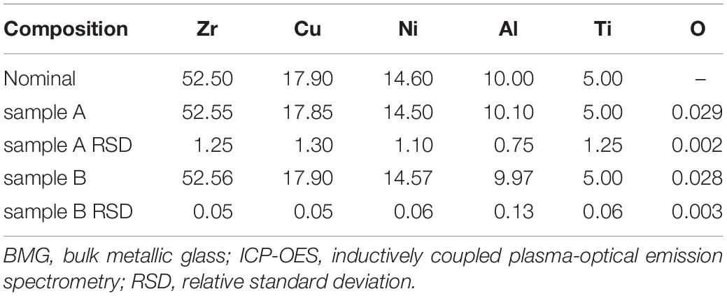
Table 1. Results of chemical analyses of Vit 105 BMG samples prepared by routes A and B: element analysis (ICP-OES in at.%) and carrier gas hot extraction oxygen analysis (in wt.%).
Exemplary XRD patterns of a Vit 105 plate sample of type A are shown in Figure 2. Those were similarly measured for cast samples of type B. After surface polishing to remove the outermost plate regions with some unidentifiable crystalline phases (up to ∼100 μm depth), in all cases, only the broad diffuse diffracted intensity maxima which are characteristic for an amorphous phase were detected (Gostin et al., 2015c). Micro-CT of several cast specimens detected a limited number of small pores with sizes <50 μm. However, this XRD analysis cannot resolve possible crystalline second phases with volume fractions <2…5%.
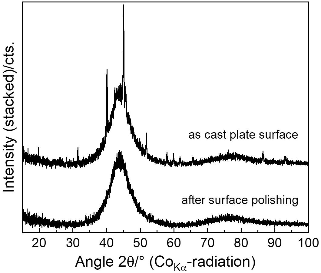
Figure 2. X-ray diffraction (XRD) pattern of Vit 105 bulk metallic glass (BMG) samples of type A, as cast and after surface polishing.
The thermal behavior of a metallic glass sample is usually a sensitive indicator for its initial structural state after solidification since the glass-forming ability correlates with the extension of the undercooled liquid region and the exothermic crystallization events provide hints regarding the homogeneity and purity of the quenched state (Gebert et al., 1998). Characteristic DSC traces of cast Vit 105 samples of types A and B are shown in Figure 3. Both sample types exhibit a very similar thermal behavior with undercooled liquid ranges of 72–74 K and a two-step crystallization sequence starting at 753–754 K. Thus, in the present study, neither differences in chemical homogeneity nor important differences in crystallite levels and so in the mechanical behavior (as presented later) can be inferred from the nearly identical DSC measurement results.
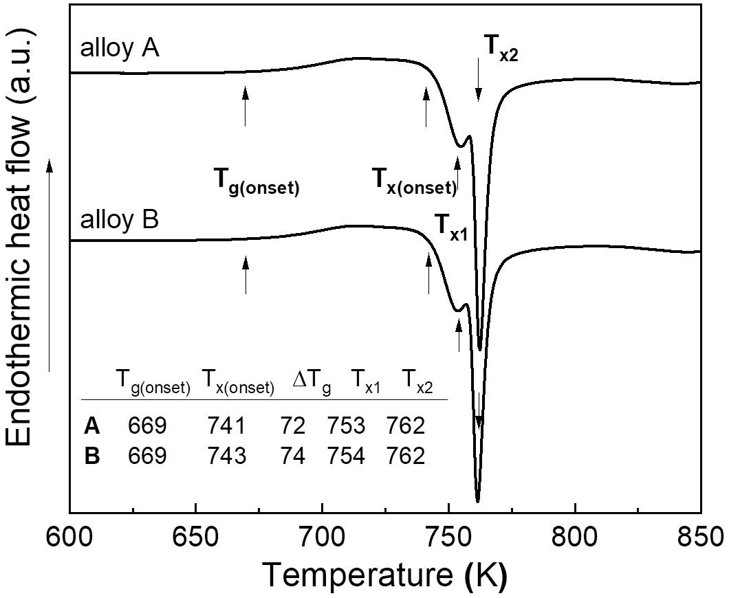
Figure 3. Differential scanning calorimetry (DSC) curves of Vit 105 bulk metallic glass (BMG) samples of types A and B recorded at a heating rate of 40 K/min.
Mechanical properties of both sample types were characterized by 3PB as well as tensile testing in air. For the 3PB experiments, chevron-notched samples were used. Typical recorded and corrected 3PB stress–deflection curves for samples of types A and B are shown in Figure 4A. For a comparison of the results of bending tests in air and in the SCC situation (section “Stress corrosion analysis”), the maximum bending stress (3PB) was calculated and used (Geissler et al., 2018). The obtained maximum tensile stress values of about 2,300 MPa at the onset of plastic deformation match very good to those data obtained for un-notched Zr52.5Cu17.9Ni14.6Al10Ti5 samples of A-type (Gostin et al., 2015c). So, this way of stress estimation (Geissler et al., 2018) is applied in the following studies.
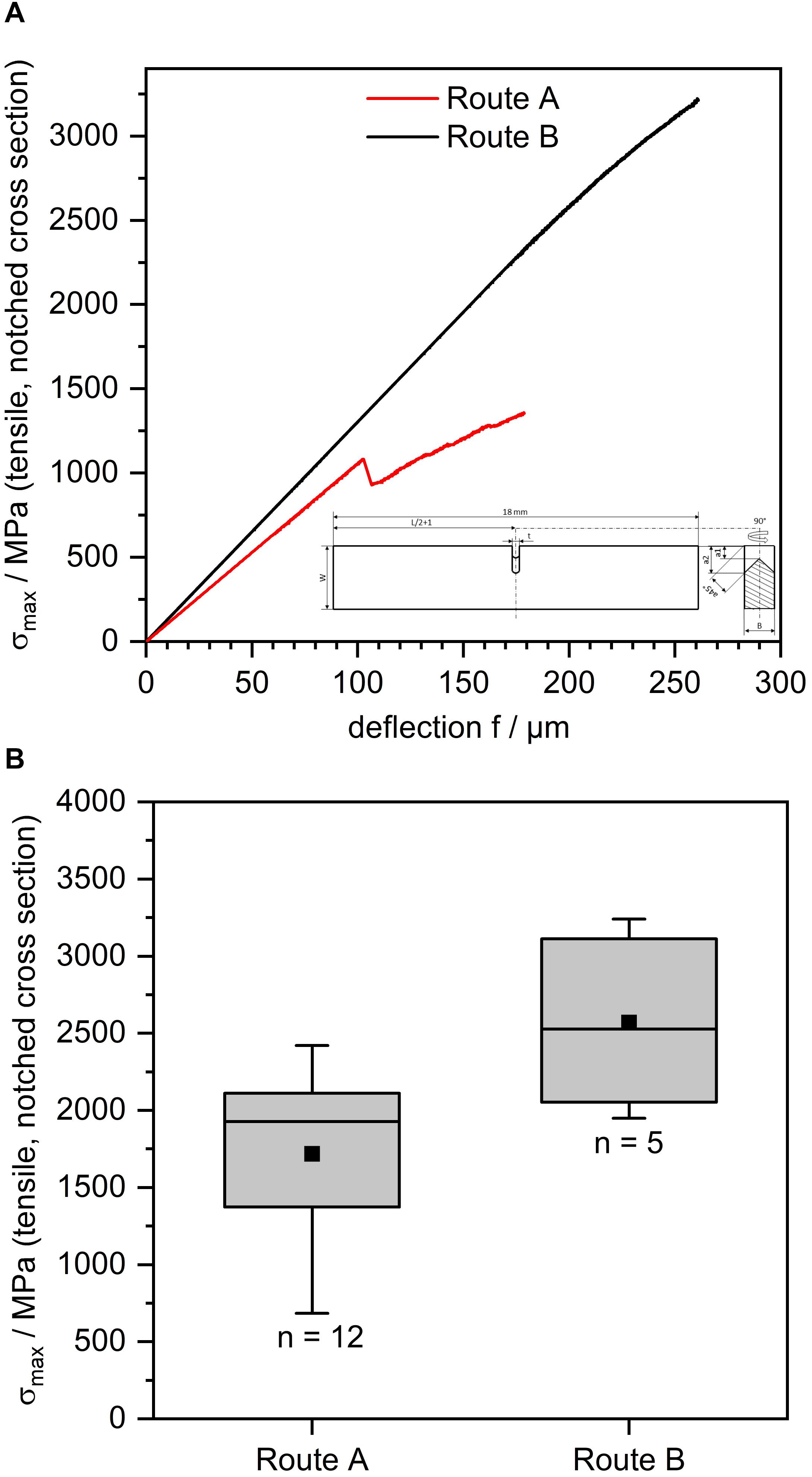
Figure 4. Three-point-bending (3PB) tests of chevron-notched samples of routes A and B in air. (A) Stress deflection curves and (B) boxplots of the maximum bending stress on the remaining ligament at fracture (n = number of tested samples).
In contrast to the thermal behavior, a distinctly different mechanical behavior was observed between the samples of routes A and B. Specimens from cast plates of route B reach much higher fracture stress levels, as demonstrated in Figure 4A comparing two example curves for 3PB specimens of the two types. The B-sample reached typical values of fracture stress of ≳3,200 MPa tensile and 2,400 MPa compressive. In contrast, those data are much lower for the A-type BMG sample which is less homogeneous. In this case, the sample began to fracture at much lower tensile stresses (σ ≳ 1,100 MPa). In the course of this comparative study with several samples of each type, selected A-type BMG 3PB specimen failed already at very low stresses, i.e., in a range of ≳685 MPa (tensile), as it was obvious from the boxplots in Figure 4B. On the other side, the lowest bending fracture stress observed for a specimen of route B was ≳1,900 MPa. Particles are the reason for the worse mechanical performance of the specimens from route A (Figure 5A) which accumulate to create sheetlike “inner surfaces” (Morrison et al., 2007). When those are located in the middle of the 3PB bending bar, i.e., in the notched zone, they can cause early failure at small stresses. In case of specimens prepared by the new route B, the probability of such detrimental particle aggregations is very low. The images of the fracture surface in Figures 5A,B that correspond to the 3PB samples in Figure 4A confirm this observation. For the specimen of route A, massive flaws are present in the fracture surface. In contrast to that, the fracture surface of the specimen of route B (Figure 5B) shows only features which were reported for bulk glassy samples subjected to similar deformation processes [e.g., Hull (1999); Morrison et al. (2007)]. The surface comprises rim regions with rough vein patterns corresponding to evident stress states and more delicate patterns in the center regions which relate to dominant strain states.
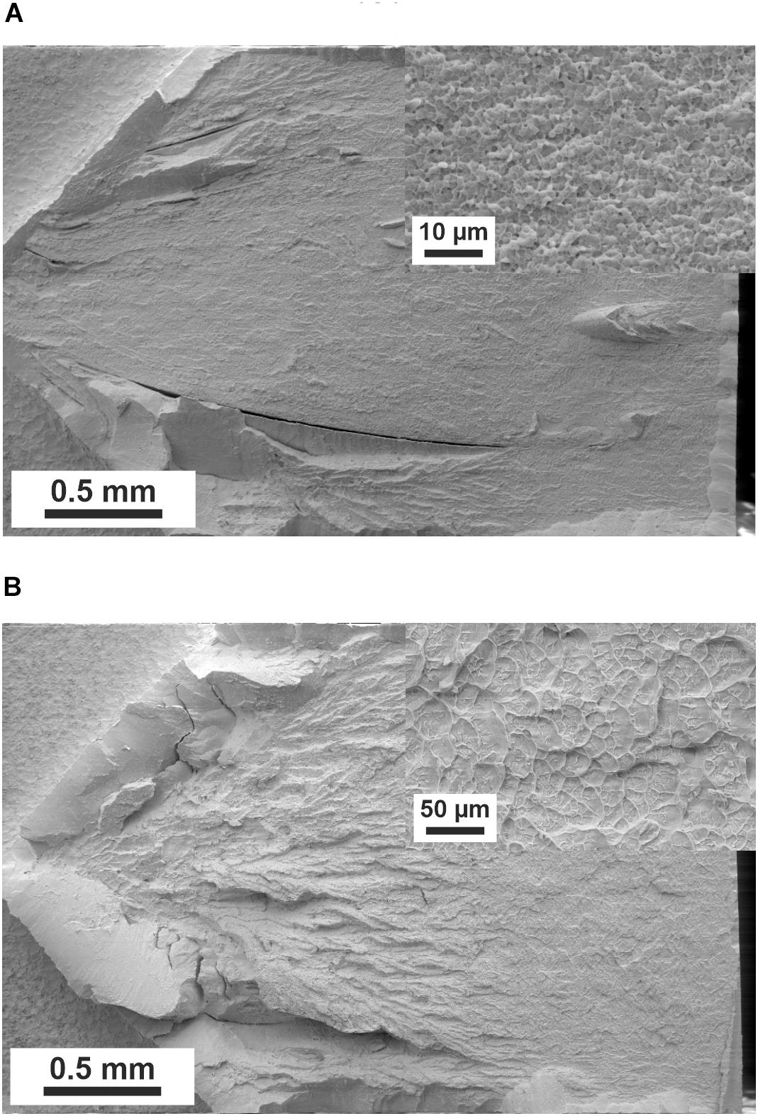
Figure 5. (A) Scanning electron microscopy (SEM) fracture surface images of the samples corresponding to the stress deflection curve in Figure 4A fracture surface of sample type A, (B) fracture surface of sample type B.
The findings of the 3PB experiments are further supported by results of conducted tensile tests. Representative stress strain curves of tensile specimens fabricated from cast plates of route A and route B are shown in Figure 6A. As already discussed for 3PB, specimens of route B possess notably higher fracture stress values and lower scattering of those. Thereby, samples from route B reached values between 1,800 and 1,845 MPa, whereas samples of route A failed between 1,710 and 1,800 MPa (Figure 6B). Tensile samples of both casting routes fractured not at or near the clamping, and for both routes, multiple fractures occurred for some samples. SEM evaluations after fracture showed in both cases cracks as well as shear bands that were not catastrophic. A notable difference is seen in the images of the fractured faces of the two BMG types. Specimens of route A show again particles and sheetlike delaminations at the fracture surface besides typical vein pattern parts (Figure 7A). In contrast, for samples of route B, these defects are not present, but only the typical vein patterns (see inset in Figure 7B). Furthermore, the depicted sample of route B showed even with the present pore (Figure 7B) a higher fracture strength than the samples of route A.
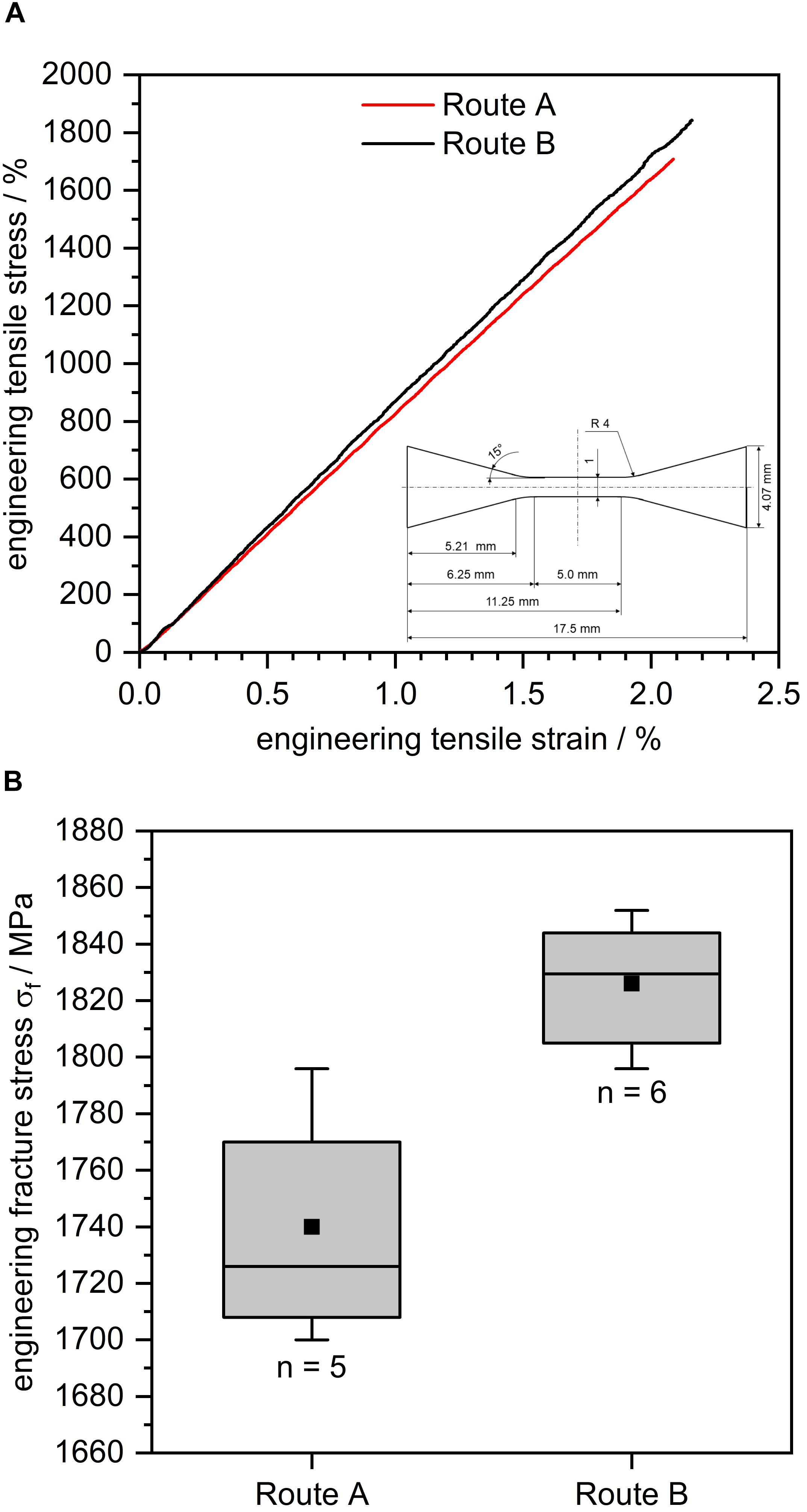
Figure 6. Tensile tests of samples of routes A and B in air. (A) Exemplary stress strain curves and (B) boxplots of the fracture stress (n = number of tested samples).
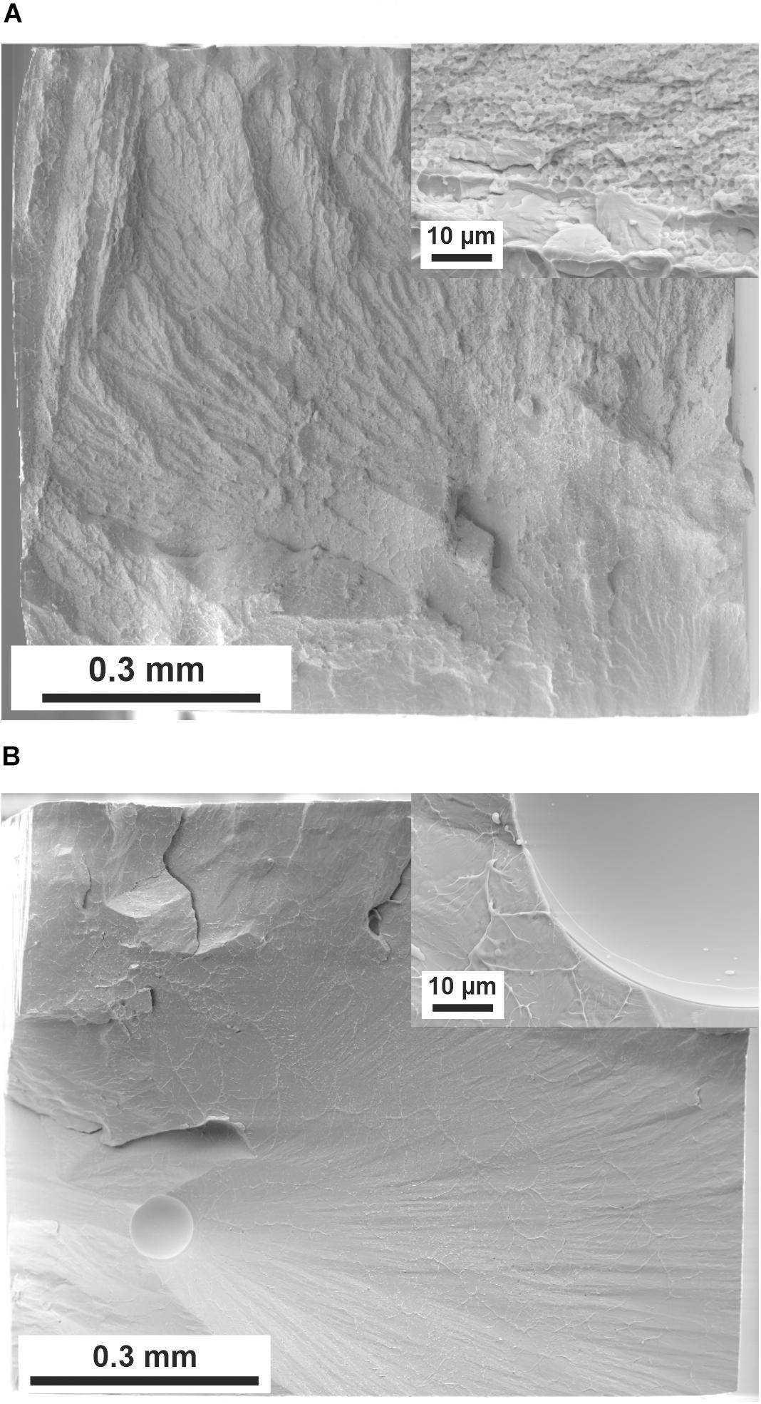
Figure 7. Scanning electron microscopy (SEM) fracture surface images of the samples corresponding to the stress strain curves depicted in Figure 6A: (A) fracture surface of sample type A, (B) fracture surface of sample type B.
In situ Analysis of Crack Propagation in Vit 105 Under Three-Point-Bending Conditions
In the following section, the crack propagation under 3PB bending conditions (S = 10 mm) will be described for a pre-notched Vit 105 specimen (route A) in air. Images were recorded in situ with a microDAC strain measurement system and ex situ using a field emission gun (FEG)-SEM. The complete crack path after testing as well as selected in situ images visualizing the crack propagation and shear band development are given in Figure 8. The force deflection curve of the sample is shown in Figure 9A. First crack initiation and propagation from the existing notch occurred at a load of 185 N and corresponds to a maximum tensile stress of about 1,670 MPa in the remaining cross section. At point 2 of the load deflection curve, the crack propagation stopped due to the extensive shear banding. The shear bands follow the theoretical solution of the fan-shaped Prandtl slip-line fields for a notched bending specimen (Green and Hundy, 1956; McClintock, 1971; Flores and Dauskardt, 1999; Chakrabarty, 2006; Zhu and Joyce, 2012; Geissler et al., 2018). In this first part, the crack propagation is fairly straight, and only small curvatures are existing due to crack deflections (Figure 8, image 2). The formation of shear bands along the crack path and in front of the crack tip is clearly visible in the in situ and SEM images. Based on the SEM images, the shear band zone has a size of about 100 μm in this first region. With ongoing deflection, further crack growth occurred at maximum tensile stress which is about 1,140 MPa in the remaining cross section. The in situ image (Figure 8, image 3) and the SEM image demonstrate the extensive formation of shear band patterns in front of the crack tip resembling the aforementioned fan-shaped slip-line field solutions. These shear band patterns correspond to the Prandtl-type slip-line fields that denote the maximum shear stress and shear velocity and demonstrate complete plastic behavior due to non-hardening or strain softening of bulk glassy alloys (Geissler et al., 2018). High normal stresses are also present orthogonal to these slip-line traces, and therefore, further crack events follow either the one or the other trace along a shear band. Thereby, the crack is deflected from its straight propagation direction. With ongoing deformation, a new slip-line field develops in front of the crack tip of the arrested crack due to partial unloading and leads again to comparatively large-scale plastic deformation and later a crack deflection. To emphasize, the formation of shear band patterns according to slip-line field solutions indicates more a plastic collapse behavior beyond the classical KI- or J-integral fracture mechanics framework (Geissler et al., 2018). This behavior is nicely visible in the in situ images (Figure 8, images 3 and 4) corresponding to part 3 of the load deflection curve. The crack propagation takes place mainly along separated shear band planes. The formed shear band zone in this sample area is even larger than 100 μm. The final crack tip after the stopped bending experiment (Figure 8, image 5; Figure 9A, region 4) at this stage is depicted in Figure 9B and demonstrates again nicely the slip-line field-like arrangement of shear bands.
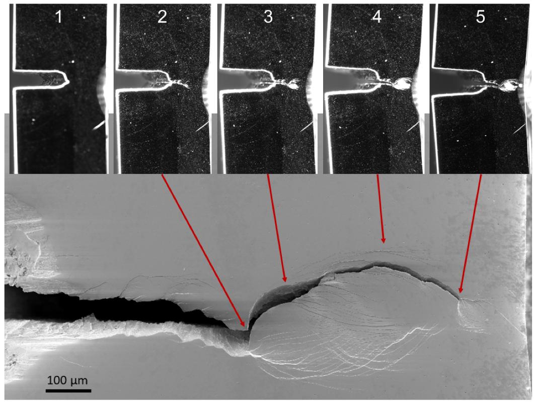
Figure 8. Crack propagation of pre-notched Vit 105 sample under three-point-bending (3PB) conditions.
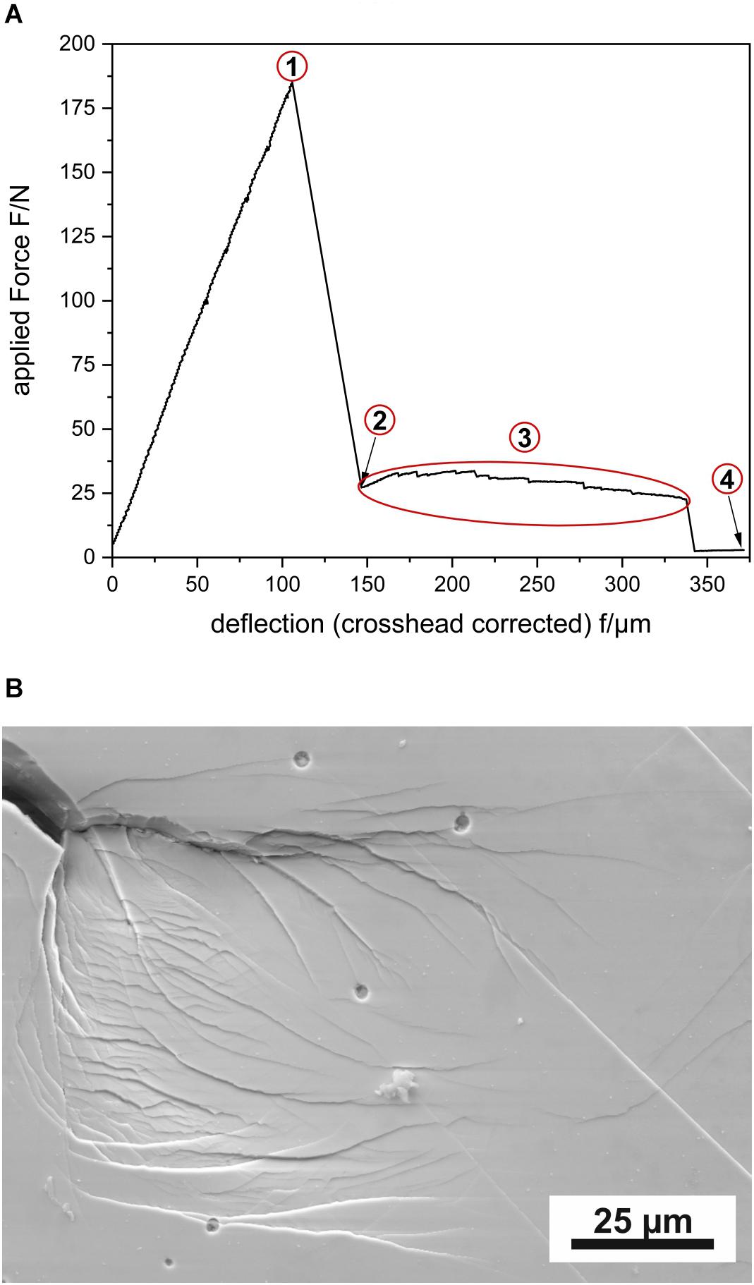
Figure 9. (A) Force deflection curve of pre-notched three-point-bending (3PB) sample in air (images of corresponding crack propagation are depicted in Figure 8 and (B) scanning electron microscopy (SEM) image of the crack tip after testing.
An electron-transparent sample was prepared by FIB from a notched three-point bending test containing four shear bands (1–4) and subsequently imaged using high-angle annular dark-field scanning transmission electron microscopy (HAADF-STEM) (Hilke et al., 2019). Alternating contrast changes along their propagation direction can be noticed for three of them (Figure 10). The contrast changes are caused by differences in the density along the shear band and have also been observed for Pd40Ni40P20 (Hieronymus-Schmidt et al., 2017) and Al88Y7Fe5 (Rösner et al., 2014; Schmidt et al., 2015). Moreover, the microstructure of the amorphous state was analyzed with respect to MRO using variable resolution fluctuation electron microscopy (VR-FEM). FEM is sensitive to MRO of disordered materials. It uses the correlation of atom pairs (pair–pair correlation function). A statistical analysis of the variance V(k, R) from diffracted intensities of nanometric volumes obtained by nano-diffraction was used to extract this information. Sampling with different parallel probe sizes, R, gives information of the structural ordering length scale. Moreover, the height of the first variance peak provides a semiquantitative measure of the MRO volume fraction. From individual nano-beam diffraction patterns (NBDPs) taken from different regions (shear band and matrix), this statistical information was extracted prior to and after deformation. Strikingly, the MRO of the matrix was strongly affected after deformation (peak height reduction). For the details, we refer to Figure 3 in Hilke et al. (2019). Figure 11 is an illustration based on the observed changes in the matrix MRO after deformation indicating the existence of a shear band-affected zone (SBAZ) (Pan et al., 2001; Maaß et al., 2014; Shen et al., 2018).
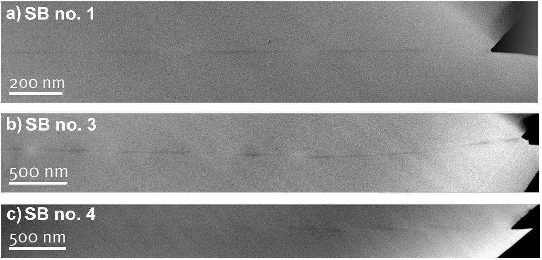
Figure 10. Contrast-enhanced high-angle annular dark-field scanning transmission electron microscopy (STEM-HAADF) micrographs showing shear bands in Vit 105 with alternating contrast changes. (a) shows a shear band (no. 1) that is aligned edge-on to the electron beam; (b) shows a shear band (no. 3) that bends toward the surface; and (c) shows shear band (no. 4) that is twisted and thus misaligned to the electron beam.
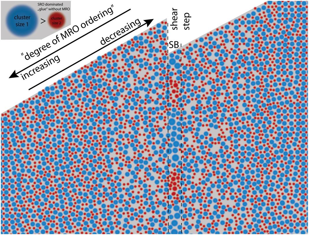
Figure 11. Schematic illustration of the medium-range order (MRO) distribution in and around a shear band indicating the influence of the deformation.
Stress Corrosion Analysis
In the project, a detailed study of the SCC process was carried out on cast Zr52.5Cu17.9Al10Ni14.6Ti5 (Vit 105) BMG samples. In 3PB tests with an environment comprising near-neutral water-based NaCl solutions, in situ recordings of stress and current density and later of the local pH value were performed, and afterward, the fractured surfaces of the samples were inspected. So, the impact of solution, electrode potential, and applied elastic load on the initiation and growth of cracks could be assessed and discussed under consideration of their particular microstructure.
First studies were conducted with un-notched rectangular bar samples of type A. In order to determine appropriate testing conditions, quasi-static bending tests in air were conducted by means of the SCC setup (section “Stress Corrosion Cracking”), and two stress levels in the elastic regime were selected, i.e., 30% and 50% of the Rp0.2. Further, potentiodynamic anodic polarization curves with re-passivation loops were recorded on embedded and polished sample cross sections in the test electrolyte 0.01 M Na2SO4 + 0.01 M NaCl and suitable potentials in the region (Erepass < Eanodic < Epit), i.e., Eanodic = −50; 0; 50 mV versus SCE have been selected. With these parameters, SCC tests were performed (Gostin et al., 2015c). From each test, a collection of data, i.e., the duration for the initiation of pitting, the initiation time for SCC and that for SCC propagation, as well as the total duration to fracture, was obtained. Results regarding the latter are shown in Figure 12A. Though there is an obvious scattering of the data, two principal trends can be derived. Firstly, for a defined load level of 50% Rp0.2 and with increasing potential, the fracture duration is reduced, and therefore, the resistance to stress corrosion declines. Further, at a given potential of +50 mV versus SCE, a lower applied load of 30% Rp0.2 causes increased durations to fractures. Also, the studies revealed the stage when the dominance of pitting changes toward a dominance of cracking which occurs earlier at an increased stress level. From those experiments, average crack growth rates were roughly estimated. For example, the rate was about 14 μm⋅s–1 for a test conducted at an initial stress of 50% of Rp0.2 and an electrode potential of 0 mV versus SCE. The value was estimated by employing SEM analysis which revealed the total length of the fractured region due to crack propagation, and this was divided by the propagation time (Gostin et al., 2015b, c).
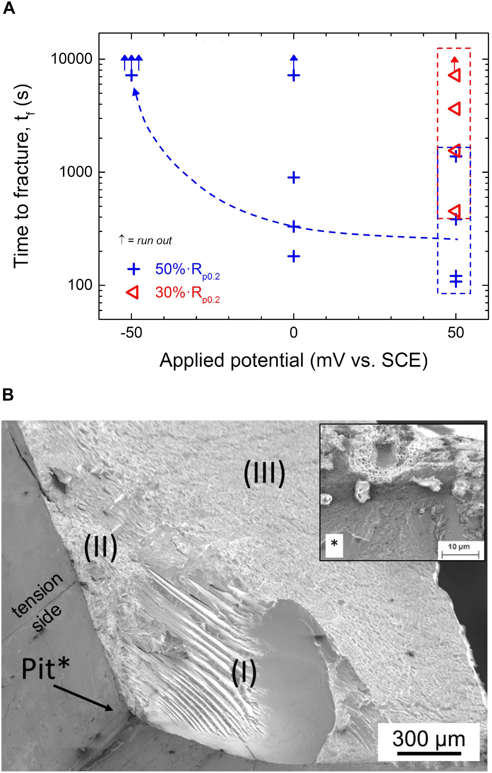
Figure 12. (A) Stress corrosion cracking (SCC) test results-total time to fracture versus applied anodic potential Eanodic for un-notched Vit 105 bars in 0.01 M Na2SO4 + 0.01 M NaCl, starting σmax = 1,301 MPa (50% of Rp0.2) and (B) scanning electron microscopy (SEM) image of fracture surface of un-notched Vit 105 sample after SCC testing (for I–III, see text).
A typical example of a fracture surface is shown in Figure 12B. Fractography of numerous samples revealed that multiple pits are typically present and are mostly located along the sample edges. Due to their sharp geometry, these edges are most preferred sites at the BMG electrode surface for chloride ion attack. This confirms critical conclusions made in earlier corrosion fatigue studies on 4PB Vit 105 samples (Morrison et al., 2007). Altogether, our SEM investigations disclosed that cracks usually started at locally corroded zones. This was similarly observed in corrosion fatigue tests which were conducted in the present project employing the same sample type A of Vit 105 3PB samples (Grell et al., 2017). The randomness of the pitting process is one reason explaining the scattering of the final times to fracture. The zones I and II correspond to different crack propagation stages. At these early stages of our studies, the features in the zone I were interpreted as indications for a crack growth with multiple superimposed processes comprising unstable but permanent brittle propagation at the rim regions of the bulk glassy sample. Toward the center of a sample, this changed to a stepped growth mode with shearing and dissolution in the crack tip zone. The characteristics of zone II were ascribed to anodic dissolution during crack propagation (Gostin et al., 2015c). However, our subsequent analyses led to new interpretations as will be also explained below (Geissler et al., 2019). Nevertheless, it is emphasized that the relative area ratio of zone I to zone II was not always the same in each experiment. For example, samples tested at the highest stress level and at the most positive electrode potential (50%⋅Rp0.2 and 50 mV) failed mostly at their middle region. There, the fracture surface was very smooth indicating that a zone II type characteristic governed the process. The observed relation between the site of the initiation of a crack and the resulting features of the fracture surface were attributed to stress fields which are present at the crack tip. We supposed that only zone II is created by true SCC, whereas zone I evolves by only superimposed mechanical fracture steps. The last period of the fracture process causes zone III which exhibits mainly vein patterns. For BMGs, those are indications for unstable growth of cracks based on shear banding (Gostin et al., 2015c). Based on those observations, a first model mechanism for the SCC process in this Zr-based BMG was proposed which comprised (i) pit formation at sample edges, (ii) pit to crack transition–cracking initiation, (iii) crack growth with increase of the stress intensity factor; a reduction of stress concentration by the formation of shear bands which can lead to a significant inhibition of the propagation of the crack, (iv) many crack branches may form due to enhanced dissolution at the shear bands, and (v) when the stress level surpasses a threshold at a tip of a generated branch, the formation of shear bands sets in again and this leads to further blunting at the crack (Gostin et al., 2015c).
However, with view to the high sensitivity of those SCC tests, the criticality of employing un-notched 3PB samples and the difficulties of having limited reproducibility of BMG sample quality were emphasized. Moreover, in a few earlier studies, there were first suggestions that hydrogen as corrosion product may play a significant role (Kawashima et al., 2010; Gostin et al., 2015b). Commonly, in the case of anodic SCC, corrosive dissolution is locally triggered by stress or plastic deformation. Indeed, many stress corrosion and corrosion fatigue analyses that were done so far on bulk glass-forming Zr alloys end with a discussion of the results only under consideration of local dissolution as driving process for the crack initiation and growth [see for example, Ritchie et al. (2000); Schroeder and Ritchie (2006); Morrison et al. (2007)]. However, corrosion reactions as steps of an SCC process can also yield hydrogen species which can be easily absorbed by metals and alloys such as Zr-based materials. Therefore, also for those amorphous alloys, effects of hydrogen embrittlement (HE) or hydrogen-induced SCC (HISCC) have to be taken into account. Kawashima et al. (2010) conducted tensile tests of Zr-BMG samples exposed to NaCl electrolytes and Nakai and Yoshioka (2010) performed deformation studies with CT samples in such environments. In both studies, the deformation test data and the analysis of the characteristics of the fracture surface led to the conclusion that hydrogen, i.e., HE, plays a crucial role in the early failure of the material. Moreover, the corrosion-assisted cracking behavior and the hydrogen sensitivity of crystalline Zr and Zircaloy-2 and -4 should also be taken into these considerations. Though they exhibit a relatively high passivation ability, a high tendency for local corrosion is given in chloride electrolytes in particular when iron or copper ions are involved. SCC processes were observed and were often attributed to embrittlement effects in consequence of the generation of Zr hydrides. On the other hand, from several studies, it was concluded that HE and SCC can take place without the accumulation of significant Zr hydrides in the deformed regions of a crack tip (Majumdar and Scully, 1979; Cox, 1990; Rebak, 2000; Farina et al., 2003). Thus, one has to take into account that there are some similarities in the hydrogen-driven mechanical behavior of crystalline and amorphous Zr-based alloys, and those have to be considered in the discussion of experimental observations gained in stress corrosion and fatigue corrosion analysis of these newer bulk glass-forming systems.
Altogether, in the subsequent 3PB-SCC tests on Zr52.5Cu17.9Al10Ni14.6Ti5, Vit 105 specimens were conducted with special emphasis on the identification of hydrogen-related phenomena (Geissler et al., 2019). All experiments were performed with notched bar specimen, and larger sample surface areas were coated with a paint, as shown in Figure 1B, in order to localize the expected degradation events in the middle of the notched bar. This was also the site for potential and pH value measurement. Both BMG sample types A and B were investigated, and no significant differences regarding the SCC mechanism were noticed. Figure 13 shows a typical result of an in situ SCC experiment with a straight-through edge notched Vit 105 3PB specimen (type B) in 0.01 M NaCl solution, i.e., the evolution of the sample response in terms of load, electrode potential, current, and pH value in dependence of time (Geissler et al., 2019). In these tests, a 0.01 M NaCl solution with pH 5.6 was employed. The free corrosion potential OCP was measured during the initial step at small pre-load F0(10N) and varied only slightly between −100 and −50 mV versus SCE. Next, under OCP conditions, the load level was slowly raised to adjust the maximum load Fmax which controlled a small deflection fexp. Here, Fmax was 177 N which is equivalent to an estimated maximum tensile stress of ≥365 MPa (Geissler et al., 2018). This is less than 12% of the value of >2,300 MPa for a 3PB(-SCC) chevron-notched specimen tested in air (see section “Analysis of Mechanical Performance and Crack Propagation in Air”; Figure 4A). When applying the load, the OCP decreased to below −400 mV. This is attributable to a breakdown of the passive film which locally exposes the free metal surface. After this initial drop down, the OCP gradually increased again, indicating a healing trend (re-passivation) of the metal surface. In a next step, the electrode potential was increased with constant rate from OCP to a potential of AP of −50 mV at the deflection fexp. When keeping AP constant, the current started to gradually rise, and the pH value decreased. From an abrupt and then stepwise load drop, a beginning cracking with several propagation steps had to be concluded. In all SCC tests, failures of the BMG specimen occurred within very short time spans, i.e., only within about a minute. Also, after the full fracture, the AP was still applied whereby the current increase and the pH value decrease continued. It is remarkable that pH values as low as pH < 4 were measured near the originally notched center region of the BMG specimen. In a last step, the external potential was switched off, and thus, the OCP and the pH value recovered gradually. However, in similar SCC experiments [not shown here but in Geissler et al. (2019)], the 3PB BMG samples started to fail already in the early period of open circuit conditions with constant deflection fexp. Also, in those cases, a significant acidification of the solution near the sample surface was measured.
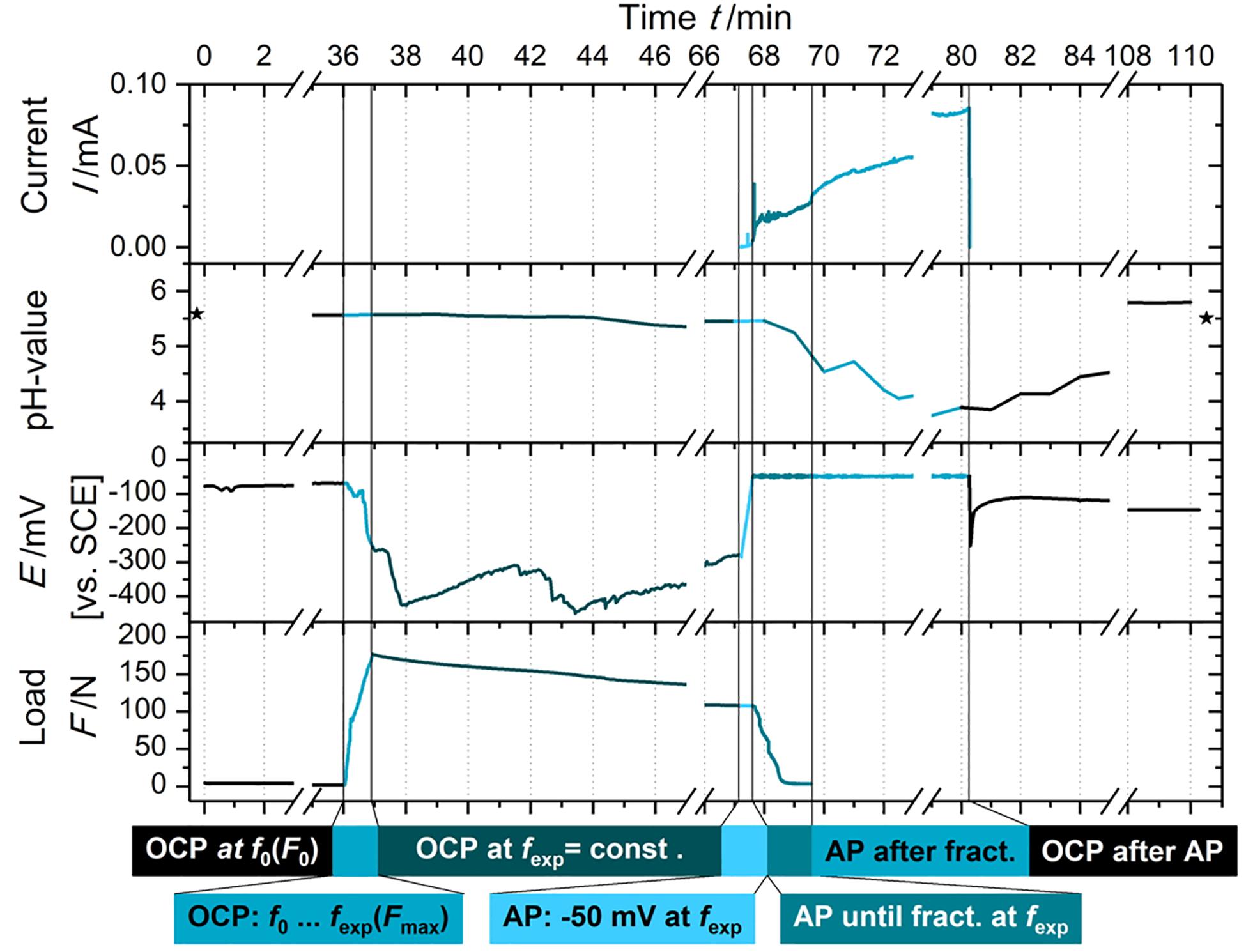
Figure 13. Stress corrosion cracking (SCC) test with a straight-through edge notched Vit 105 three-point-bending (3PB) specimen (type B) in 0.01 M NaCl solution: evolution of load, electrode potential, current, and pH value in dependence of exposure time (Geissler et al., 2019, open-access article with Elsevier user license CC BY 4.0).
After those SCC experiments, the test electrolytes were analyzed regarding metal release with ICP-OES, and large amounts of Zr species and Al, Ti, and Ni species and to a lesser extent Cu species were detected. Detailed microscopic fractography was done after all SCC tests, and typical examples are shown in Figure 14A for the sample subjected to the SCC test plotted in Figure 13 and in Figure 14B for a Vit 105 sample that failed already during loading under OCP immersion.
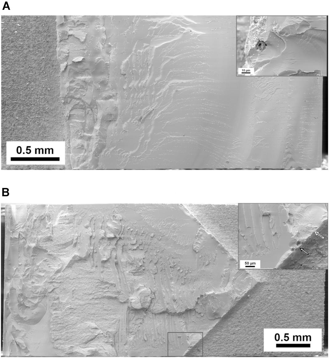
Figure 14. (A) Scanning electron microscopy (SEM) image of a fracture surface of straight-through edge notched Vit 105 three-point-bending (3PB) specimen after stress corrosion cracking (SCC) test in Figure 13, inset: site of pitting and most plausible crack initiation and (B) SEM image of a fracture surface of a chevron-notched Vit 105 3PB specimen which failed upon SCC testing at open-circuit potential (OCP) condition, inset and lower box: pitting and possible crack initiation.
In comparison to 3PB overload failure in air (section “Analysis of Mechanical Performance and Crack Propagation in Air”), after testing under SCC conditions in 0.01 M NaCl solution, the fracture surface appearances are completely different. This was already evident upon visual inspection of the fractured specimen. From typical surface images that are exemplarily shown in Figure 14A, a conchoidal fracture has to be derived which is typical for very brittle materials (Hull, 1999). In 3PB SCC tests which were conducted at higher applied loads, also mixed fracture modes occurred. Those comprised in addition smaller regions with characteristics of overload fractures which were observed and described for fracture surfaces generated in air. This is exemplarily shown in Figure 14B for a notched BMG bar specimen which partially fractured already during exposure under open circuit conditions and applied load. The insets of Figures 14A,B reveal that pitlike corrosion damages occurred at the outer edges of the specimens and also at the bottoms of the notches. Close to those, the morphologies of the fracture surface are indicative for a change from local corrosion to conchoidal fracture. This appears to be a typical characteristic of the stress corrosion process of Zr-based BMGs.
Finally, when analyzing the basic morphologies of corroded areas in pits as reported in various publications [e.g., in Gostin et al. (2015a, c)] and under consideration of the typical fracture surface features which were observed in the present study as well in an earlier report (Kawashima et al., 2010), it has to be concluded that a main reason for macroscopic failure upon SCC testing of Zr-based BMGs even under free corrosion and anodic control is HE or hydrogen-induced SCC (HISCC).
A reason why hydrogen-related effects are mostly excluded during corrosion testing of Zr-based BMG samples in near-neutral water-based tests electrolytes is that relevant electrode potentials seem to be by far too positive, i.e., too far away from the cathodic hydrogen reduction potential. However, if only small actively corroding sites like pits or cracks are present on an otherwise passive metal surface, a mixed electrode potential is measured. Thus, the potential of an active site is unknown but must be very negative in the present case. In the SCC tests, this was obvious from the significant drops of the OCP by several hundreds of millivolts upon mechanical loading (Figure 13) which is due to the rupture of the natural passive film or even first pitting. Similar as reported in some earlier works, our present studies on Zr52.5Cu17.9Al10Ni14.6Ti5 (Vit 105) 3PB samples in NaCl solutions under OCP or anodic conditions revealed that local anodic dissolution (pitting) is the typical initial step of a stress corrosion process. Similar to other Zr-based BMG alloys (Gostin et al., 2015a), the major constituent Zr mainly dissolves whereby hardly soluble Cu compounds remain enriched as residues in the corroded surface areas. Zr is a strong base metal, its standard electrode potential is E = −1.8 V – this is far below the stability range of water which is ∼1.5 V more positive. Thus, in solutions with pH < 6.6, the Zr metal tends to dissolve and the Zr4+ ions are subjected to complex hydrolysis reactions, leading to zirconyl ions ZrO2+ and protons H+ (Pourbaix, 1966). Our in situ pH value measurements during SCC testing revealed significant acidification (Figure 13), and this indicated that those processes can occur also in case of a Zr-based metallic glass. When the main alloy component Zr actively dissolves in localized areas such as a pit or crack, this can cause instantaneously the generation of hydrogen atoms. Those can be reduced at the very negative bare BMG surface site, and finally, adsorbed hydrogen atoms will be absorbed. Fundamental studies regarding hydrogen uptake of Zr-based glass-forming alloys revealed that the hydrogen solubility and diffusivity can be remarkable (Eliaz and Eliezer, 1999; Ismail et al., 2002). Hydrogen atoms can be incorporated in the (un-deformed) SRO/MRO structure of the metallic glass by successively occupying interstitial tetrahedral sites of different energy levels (Bankmann et al., 2003; Gostin et al., 2015b). In situ generated and absorbed hydrogen atoms in a crack tip region will have significant effects on shear band-driven crack propagation and on the local SRO/MRO structure. It should be a matter of further studies to analyze those local structural changes in the presence of interstitial hydrogen atoms and to clarify consequences for shear band formation and propagation. Nonetheless, from our macroscopic test results, we have sufficient evidence for hydrogen-driven catastrophic failure of the Vit 105 3PB SCC samples. This seems to be to a certain extent contradictive to results of studies where mechanical properties of Zr-based BMG samples were analyzed under sustained or cyclic loading conditions and cathodic hydrogen (pre-)charging (Gostin et al., 2015b). Our experimental findings elucidated that corrosion processes such as chloride-induced pitting or local dissolution as a consequence of mechanical passive film rupture are the first steps to start hydrogen-related cracking processes (HE, HISCC).
Summary and Conclusion
Though Zr52.5Cu17.9Ni14.6Al10Ti5 (Vit 105) is one of the known Zr-based alloys with the highest glass-forming ability, the casting conditions for BMG sample production persist a critical issue finally influencing the mechanical and corrosion performances. A new approach of a copper mold casting process using binary pre-alloys as starting materials yields more homogeneous and reproducible bulk amorphous sample qualities. In consequence, upon quasi-static 3PB (notched specimen) and tensile testing in air, those BMG types exhibited generally notably higher fracture stress levels and only fracture surface features which are typical for single-phase glassy states. In contrast, BMG types, classically produced by using single constituent elements as starting materials, contained partially segregated small particles (crystallites) that caused early failure at lower stresses.
In situ analysis during 3PB of pre-notched BMG samples in air revealed a complex crack propagation mechanism mainly driven by shear banding. The extensive formation of shear band patterns in front of the crack tip resembled fan-shaped slip-line field solutions. These patterns correspond to the Prandtl-type slip-line fields that denote the maximum shear stress and shear velocity and elucidate fully plastic behavior in result of the non-hardening or even strain softening of BMGs. High normal stresses are also present orthogonal to these slip-line traces, and therefore, further crack events follow either the one or the other trace along a shear band. Thereby, the crack is deflected from its straight propagation direction. With ongoing deformation, a new slip-line field develops in front of the crack tip of the arrested crack due to partial unloading and leads again to comparatively large-scale plastic deformation and later a crack deflection. Shear band regions resulting from such a 3PB test were imaged and analyzed by HAADF-STEM and VR-FEM. These observations manifest significant structural changes induced by deformation. Such changes are not only limited to the shear bands but also affected their immediate environment by altering the MRO of the matrix and thus confirm the existence of shear-affected zones around shear bands (SBAZ).
Corrosive aqueous environments have a great detrimental effect on the mechanical performance of those Zr-based BMGs, which largely exceeds impacts of above-stated different sample qualities. The focus of this project was on the detailed analysis of SCC phenomena for Vit 105 samples in selected chloride-containing electrolytes. First, 3PB tests with un-notched bar specimen in solution under in situ control of the electrochemical response revealed significant effects of increasing applied elastic load levels and increasing anodic potentials toward a reduction of the total time to fracture. Further SCC tests with notched 3PB specimen conducted in 0.01 M NaCl solution demonstrated that due to corrosive attack comprising not only metal dissolution but also hydrogen formation, the applied load to attain material failure load is much smaller than that determined when similar tests were performed in air. SEM fractography revealed characteristic surface morphologies which are typical for conchoidal fractures of very brittle materials.
In summary of all experimental observations, it is concluded that pitting at surface defects is the typical initiation step followed by a mainly HISCC process, which leads to catastrophic failure. The chemical composition of Vit 105 with Zr and Cu as main constituents appears to be problematic as those facilitate the pitting process and enable the local generation of hydrogen. It is known that hydrogen atoms can be incorporated in the SRO/MRO structure of a Zr-based metallic glass by successively occupying interstitial sites of different energy levels. It is expected that in situ generated and absorbed hydrogen atoms in a stressed crack tip region will have significant effects on the local SRO/MRO structure and on the shear band-driven crack propagation. This should be a matter of further detailed analytical studies. However, according to our present state of knowledge, the catastrophic stress corrosion failure evidenced for Vit 105 BMG samples must be generalized to Zr–Cu-based BMG types with similar compositions. In conclusion, this supports our opinion that this BMG family is not applicable in corrosive environments.
Data Availability Statement
All datasets generated for this study are included in the article/supplementary material.
Author Contributions
DG planned and conducted the experimental work on alloy preparation and characterization, mechanical testing, in situ crack analysis in air, and stress corrosion cracking analysis. SP helped him with the analysis, discussion, and manuscript presentation of the mechanical testing results and the in situ crack analysis. MU contributed to hydrogen analysis and the discussion of hydrogen-induced stress corrosion cracking. AG was the PI of this project with two funding periods and was involved in the experimental planning and discussion of experimental results, prepared main parts of this manuscript which reviews the highlight results of the project. All authors from Münster contributed equally to this manuscript.
Conflict of Interest
The authors declare that the research was conducted in the absence of any commercial or financial relationships that could be construed as a potential conflict of interest.
Funding
DG and AG gratefully acknowledge the financial support by the German Research Foundation (DFG) under grant GE 1106/11 (project 224063632) as well as the Materials Physics Group of G. Wilde under grant WI 1899/27 (project 325408982). The DFG is further acknowledged for funding the TEM equipment in Münster via the Major Research Instrumentation Program under INST 211/719-1 FUGG. P.F. Gostin from IFW Dresden and E. Kerscher and D. Grell from the University of Kaiserslautern (grant KE 1426/4) are gratefully acknowledged for their scientific contributions to this project within the first funding period.
Acknowledgments
The authors are grateful to J. Freudenberger, T.G. Woodcock, H. Wendrock, S. Oswald, and C. Damm from IFW Dresden and M. Zimmermann from TU Dresden for fruitful scientific discussions and for analytical support. Further technical assistance of T. Sturm, S. Donath, B. Gebel, L. Ewenz K. Hennig, M. Johne A. Voß, R. Buckan, H. Bußkamp, S. Kaschube, and the Research Technology Division of IFW Dresden is appreciated. P. Schrems from IPS Elektroniklabor GmbH & Co. KG is acknowledged for technical help.
References
Almyras, G. A., Lekka, C. E., Mattern, N., and Evangelakis, G. A. (2010). On the microstructure of the Cu65Zr35 and Cu35Zr65 metallic glass. Scripta Mater. 62, 33–36. doi: 10.1016/j.scriptamat.2009.09.019
Bankmann, J., Pundt, A., and Kirchheim, R. (2003). Hydrogen loading behaviour of multi-component amorphous alloys: model and experiment. J. Alloys Compd. 356-357, 566–569. doi: 10.1016/S0925-8388(02)01278-1
Cheng, Y. Q., Cao, A. J., Sheng, H. W., and Ma, E. (2008). Local order influences initiation of plastic flow in metallic glass: effects of alloy composition and sample cooling history. Acta. Mater. 56, 5263–5275. doi: 10.1016/j.actamat.2008.07.011
Cox, B. (1990). Environmentally-induced cracking of zirconium alloys - a review. J. Nucl. Mater. 170, 1–23. doi: 10.1016/0022-3115(90)90321-D
Deng, L., Gebert, A., Zhang, L., Chen, H. Y., Gu, D. D., Kuehn, U., et al. (2019). Mechanical performance and corrosion behaviour of Zr-based bulk metallic glass produced by selective laser melting. Mater. Design 189:108532. doi: 10.1016/j.matdes.2020.108532
Eliaz, N., and Eliezer, D. (1999). An overview of hydrogen interaction with amorphous alloys. Adv. Perform. Mater. 6, 5–31. doi: 10.1023/A:1008748627295
Farina, S., Duffo, G., and Galvele, J. (2003). Stress corrosion cracking of zirconium and Zircaloy-4 in halide aqueous solutions. Corros. Sci. 45, 2497–2512. doi: 10.1016/S0010-938X(03)00075-1
Flores, K. M., and Dauskardt, R. H. (1999). Enhanced toughness due to stable crack tip damage zones in bulk metallic glasses. Scripta Mater. 41, 937–943. doi: 10.1016/S1359-6462(99)00243-2
Gebert, A., Eckert, J., and Schultz, L. (1998). Effect of oxygen on phase formation and thermal stability of slowly cooled Zr65Cu17.5Al7.5Ni10 metallic glass. Acta Mater. 46, 5475–5482. doi: 10.1016/S1359-6454(98)00187-6
Gebert, A., Gostin, P. F., Uhlemann, M., Eckert, J., and Schultz, L. (2012). Interactions between mechanically generated defects and corrosion phenomena of Zr-based bulk metallic glasses. Acta Mater. 60, 2300–2309. doi: 10.1016/j.actamat.2011.12.044
Geissler, D., Freudenberger, J., Wendrock, H., Zimmermann, M., and Gebert, A. (2018). On sample size effects in fracture toughness determination of bulk metallic glasses. Eng. Frac. Mech. 202, 500–507. doi: 10.1016/j.engfracmech.2018.09.020
Geissler, D., Uhlemann, M., and Gebert, A. (2019). Catastrophic stress corrosion failure of Zr-base bulk metallic glass through hydrogen embrittlement. Corros. Sci. 159:108057. doi: 10.1016/j.corsci.2019.06.012
Gilbert, C. J., Ritchie, R. O., and Johnson, W. L. (1997). Fracture toughness and fatigue-crack propagation in a Zr-Ti-Ni-Cu-Be bulk metallic glass. Appl. Phys. Lett. 71, 476–478. doi: 10.1063/1.119610
Gostin, P. F., Eigel, D., Grell, D., Eckert, J., Kerscher, E., and Gebert, A. (2015a). Comparing the pitting corrosion behavior of prominent Zr-based bulk metallic glasses. J. Mater. Res. 30, 233–241. doi: 10.1557/jmr.2014.371
Gostin, P. F., Eigel, D., Grell, D., Uhlemann, M., Kerscher, E., Eckert, J., et al. (2015b). Stress corrosion cracking of a Zr-based bulk metallic glass. Mater. Sci. Engg. A 639, 681–690. doi: 10.1016/j.msea.2015.05.049
Gostin, P. F., Eigel, D., Grell, D., Uhlemann, M., Kerscher, E., Eckert, J., et al. (2015c). Stress-corrosion interactions in Zr-based bulk metallic glasses. Metals 5, 1262–1278. doi: 10.3390/met5031262
Green, A. P., and Hundy, B. B. (1956). Initial plastic yielding in notch bend test. J. Mech. Phys. Solids. 4, 128–144. doi: 10.1016/0022-5096(56)90085-0
Grell, D., Gostin, P. F., Eckert, J., Gebert, A., and Kerscher, E. (2015). In situ electrochemical analysis during deformation of a Zr-based bulk metallic glass: a sensitive tool revealing early shear banding. Adv. Eng. Mater. 17, 1532–1535. doi: 10.1002/adem.201500273
Grell, D., Wilkin, Y., Gostin, P. F., Gebert, A., and Kerscher, E. (2017). Corrosion fatigue studies on bulk glassy Zr-based alloy under three-point bending. Front. Mater. 3:60. doi: 10.3389/fmats.2016.00060
Hieronymus-Schmidt, V., Rösner, H., Wilde, G., and Zaccone, A. (2017). Shear banding in metallic glasses described by alignments of Eshelby quadrupoles. Phys. Rev. B 95:134111. doi: 10.1103/PhysRevB.95.134111
Hilke, S., Roesner, H., Geissler, D., Gebert, A., Peterlechner, M., and Wilde, G. (2019). The influence of deformation on the medium-range order of a Zr-based bulk metallic glass characterized by variable resolution fluctuation electron microscopy. Acta Mater. 171, 275–281. doi: 10.1016/j.actamat.2019.04.023
Hull, D. (1999). Fractography: Observing, Measuring and Interpreting Fracture Surface Topography. Cambridge, MA: University Press.
Ismail, N., Uhlemann, M., Gebert, A., Eckert, J., and Schultz, L. (2002). The electrochemical hydrogen sorption behaviour of Zr-Cu-Al-Ni metallic glasses. Mater. Trans. 43, 1133–1137. doi: 10.2320/matertrans.43.1133
Kawashima, A., Yokoyama, Y., and Inoue, A. (2010). Zr-based bulk glassy alloy with improved resistance to stress corrosion cracking in sodium chloride solutions. Corros. Sci. 52, 2950–2957. doi: 10.1016/j.corsci.2010.05.007
Kruzic, J. J. (2011). Understanding the problem of fatigue in bulk metallic glasses. Metall. Mater. Trans. A 42, 1516–1523. doi: 10.1007/s11661-010-0413-1
Lekka, C. E., Bokas, G. B., Almyras, G. A., Papgeorgiou, D. G., and Evangelakis, G. A. (2012). Clustering, microalloying and mechanical properties in Cu/Zr-based glassy models by molecular dynamics simulation and ab-initio computation. J. Alloys Compd. 536, 65–69. doi: 10.1016/j.jallcom.2011.11.038
Lewandowski, J. J., Wang, W. H., and Greer, A. L. (2005). Intrinsic plasticity or brittleness of metallic glasses. Phil. Mag. Lett. 85, 77–87. doi: 10.1080/09500830500080474
Maaß, R., Samwer, K., Arnold, W., and Volkert, C. (2014). A single shear band in a metallic glass: local core and wide soft zone. Appl. Phys. Lett. 105:171902. doi: 10.1063/1.4900791
Madge, S. V. (2015). Toughness of bulk metallic glasses. Metals 5, 1279–1305. doi: 10.3390/met5031279
Majumdar, P., and Scully, J. (1979). Reversible embrittlement in zircaloy-2. Corros. Sci. 19, 141–145. doi: 10.1016/0010-938X(79)90047-7
McClintock, F. A. (1971). “Plasticity aspects of fracture,” in Fracture - An Advanced Treatise, ed. H. Liebowitz (New York: Academic Press), 48–225.
Morrison, M. L., Buchanan, R. A., Liaw, P. K., Green, B. A., Wang, G. Y., Liu, C. T., et al. (2007). Corrosion-fatigue studies of the Zr-based Vitreloy 105 bulk metallic glass. Mater. Sci. Eng. A 467, 198–206. doi: 10.1016/j.msea.2007.03.106
Nakai, Y., and Yoshioka, Y. (2010). Stress corrosion and corrosion fatigue crack growth of Zr- based bulk metallic glass in aqueous solutions. Metall. Mater. Trans. A 41, 1792–1798. doi: 10.1007/s11661-009-9945-7
Pan, J., Chen, Q., Liu, L., and Li, Y. (2001). Softening and dilatation in a single shear band. Acta Mater. 59, 5146–5158. doi: 10.1016/j.actamat.2011.04.047
Pourbaix, M. (1966). Atlas of Electrochemical Equilibria in Aqueous Solutions. Oxford: Pergamon Press.
Ritchie, R. O., Schroeder, V., and Gilbert, C. (2000). Fracture, fatigue and environmentally-assisted failure of a Zr-based bulk amorphous metal. Intermetallics 8, 469–475. doi: 10.1016/S0966-9795(99)00155-7
Rösner, H., Peterlechner, M., Kübel, C., Schmidt, V., and Wilde, G. (2014). Density changes in shear bands of a metallic glass determined by correlative analytical transmission electron microscopy. Ultramicroscopy 142, 1–9. doi: 10.1016/j.ultramic.2014.03.006
Schmidt, V., Rösner, H., Peterlechner, M., Wilde, G., and Voyles, P. M. (2015). Quantitative measurement of density in a shear band of metallic glass monitored along its propagation direction. Phys. Rev. Lett. 115:035501. doi: 10.1103/PhysRevLett.115.035501
Schroeder, V., and Ritchie, R. O. (2006). Stress-corrosion fatigue-crack growth in a Zr-based bulk amorphous metal. Acta Mater. 54, 1785–1794. doi: 10.1016/j.actamat.2005.12.006
Schuh, C. A., Hufnagel, T. C., and Ramamurty, U. (2007). Mechanical behaviour of amorphous alloys. Acta Mater. 55, 4067–4109. doi: 10.1016/j.actamat.2007.01.052
Scully, J. R., Gebert, A., and Payer, J. H. (2007). Corrosion and related mechanical properties of bulk metallic glasses. J. Mater. Res. 22, 302–313. doi: 10.1557/jmr.2007.0051
Shen, L., Luo, P., Hu, Y., Bai, H., Sun, Y., Sun, B., et al. (2018). Shear-band affected zone revealed by magnetic domains in a ferromagnetic metallic glass. Nat. Commun. 9:4414. doi: 10.1038/s41467-018-06919-2
Trexler, M. M., and Thadhani, N. N. (2010). Mechanical properties of bulk metallic glasses. Prog. Mater. Sci. 55, 759–839. doi: 10.1016/j.pmatsci.2010.04.002
Wondraczek, L., Mauro, J. C., Eckert, J., Kühn, U., Horbach, J., Deubener, J., et al. (2011). Towards ultrastrong glasses. Adv. Mater. 23, 4578–4586. doi: 10.1002/adma.201102795
Yokoyama, Y. (2015). Development of an automatic fabrication system for cast glassy alloys. Metall. Mater. Trans. B 46, 893–905.
Zhang, Y., Mattern, N., and Eckert, J. (2011). Effect of uniaxial loading on the structural anisotropy and the dynamics of atoms of Cu50Zr50 metallic glasses within the elastic regime studied by molecular dynamic simulation. Acta Mater. 59, 4303–4313. doi: 10.1016/j.actamat.2011.03.054
Keywords: bulk metallic glass, zirconium alloy, cracking, shear bands, pitting, hydrogen, corrosion
Citation: Gebert A, Geissler D, Pilz S, Uhlemann M, Davani FA, Hilke S, Rösner H and Wilde G (2020) Studies on Stress Corrosion Cracking of Vit 105 Bulk Metallic Glass. Front. Mater. 7:128. doi: 10.3389/fmats.2020.00128
Received: 09 January 2020; Accepted: 20 April 2020;
Published: 02 June 2020.
Edited by:
Tanguy Rouxel, University of Rennes 1, FranceCopyright © 2020 Gebert, Geissler, Pilz, Uhlemann, Davani, Hilke, Rösner and Wilde. This is an open-access article distributed under the terms of the Creative Commons Attribution License (CC BY). The use, distribution or reproduction in other forums is permitted, provided the original author(s) and the copyright owner(s) are credited and that the original publication in this journal is cited, in accordance with accepted academic practice. No use, distribution or reproduction is permitted which does not comply with these terms.
*Correspondence: Annett Gebert, a.gebert@ifw-dresden.de