Seismic performance investigation of an innovative steel shear wall with semi-rigid beam-to-column connections
 Wahab Abdul Ghafar1,2
  Tao Zhong1,2*
  Muhammad Abid3*
  Enamullah Faizan4 Abdullah Mohamed5
  Ahmed M. Yosri6,7
- 1Civil Engineering and Architecture Faculty, Kunming University of Science and Technology, Kunming, China
- 2Yunnan Earthquake Engineering Research Institute, Kunming, China
- 3College of Aerospace and Civil Engineering, Harbin Engineering University, Harbin, China
- 4College of Civil and Transportation Engineering, Hohai University, Nanjing, China
- 5Research Centre, Future University in Egypt, New Cairo, Egypt
- 6Department of Civil Engineering, College of Engineering, Jouf University, Sakakah, Saudi Arabia
- 7Civil Engineering Department, Faculty of Engineering, Delta University of Science and Technology, Belkas, Egypt
Steel plate shear walls (SPSWs) are a robust lateral load resistance structure because of their high ductility and efficient energy dissipation when subjected to seismic loads. This research investigates the seismic performance of an innovative infill web strip (IWS-SPSW) and a typical unstiffened steel plate shear wall (USPSW). As a result, two 1:3 scale specimens of an IWS-SPSW and USPSW with a single story and a single bay were built and subjected to a cyclic lateral loading methodology. In the prototype, semi-rigid end-plate connectors for the beam-to-column connections were utilized. The test result of IWS-SPSW showed outstanding ductility and shear load-bearing capacity without cracks or damage. Additionally, the IWS-SPSW exhibited strong energy dissipation without substantial beam-column connection distortion. USPSW showed excellent shear load-bearing capacity, low ductility, extensive infill plate corner tearing, and large infill web plate cracks. The FE models were developed and verified against experimental data. It has been shown that the infill web strips can affect the high performance and overall energy dissipation of an SPSW system. In addition, a parametric study was conducted to investigate the infill web strip material properties, such as steel strength and thickness, that can significantly enhance the system’s seismic performances.
1 Introduction
Steel shear walls are novel lateral load-resisting systems that can brace a building against wind and seismic impacts. The geometric structure comprises one-story steel plates interconnected to beams and columns. The plates are placed in one or more bays to create a robust cantilever wall that can resist earthquakes (Choi and Park, 2009; Hou et al., 2021; Tian et al., 2021). The panels can be stiffened or unstiffened, and the surrounding steel structure can use either moment-resistant or direct beam-to-column connections (Wang M.et al., 2021; Wang W. et al., 2021; Yang et al., 2021). SPSWs are appropriate for either the construction of new steel or concrete structures or the seismic retrofitting of existing ones. The technique is anticipated to be less expensive than concrete shear walls because foundation costs will be decreased, the amount of rentable floor surface will be enhanced, and only one trade will be required on the construction site (Khaloo et al., 2021; Kim et al., 2021; Kordzangeneh et al., 2021). When an unstiffened steel shear wall is used, the creation of an SPSW core is a process that is considered to be quite simple. Because of their inherent resistance to seismic loads, SPSWs are an excellent choice of lateral load-resisting system for earthquake-prone area buildings. When implementing moment-resisting beam-to-column connections, the SPSWs offer high initial stiffness, robust resistance to degradation under cyclic loading, inherent redundancy, and significant energy dissipation (Sarcheshmehpour et al., 2021; Yu et al., 2021; Qing et al., 2022).
Buckling can occur at relatively light loads in an SPSW due to the thin panel, and the resistance of the panel is controlled by the action of the tension field (Khalilzadehtabrizi et al., 2021; Ozcelik, 2021; Abdul Ghafar et al., 2022) Because of this, the diagonal tension field causes boundary elements (Beam, Columns) to experience significant axial forces and flexural moments, making it challenging to design columns for multistory buildings (Jin et al., 2021; Meng et al., 2021). SPSWs are not extensively employed in buildings because of this critical issue. Many strategies have developed in addition to new types of SPSW structures to reduce the significant demand for vertical boundary elements brought on by diagonal tension in web plates. Berman et al. (2005) conducted a cyclic test on light-gauge SPSWs; the test result revealed a more considerable ductility and less lateral stiffness than typical SPSWs. Low Yield Point LYP-SPSWs were studied by (Zhang and Zirakian, 2015) and demonstrated the potential to create high-performance SPSW systems structurally and seismically while remaining reasonably affordable. Lu et al. (2018) studied SPSWs with unequal-length slits. They reported that experimental data and FE modeling confirm that the slits reduce the steel plate shear wall’s ultimate bearing capacity and lateral stiffness. Haji Mirsadeghi and Fanaie (2021) studied analytically partially connected web plates to columns in an SPSW. It proved that the flexure and stiffness demand on the vertical boundary elements (VBEs) is decreased in these steel shear walls by minimizing the interconnection length between the infill and the vertical boundary element. In another research by (Hajimirsadeghi and Fanaie, 2021; Shin and Kim, 2022), the SPSWs that were carried out involved a significant amount of disconnected length of web plate to vertical boundary columns. The findings of the experiments and the numerical analysis showed that the flexure and stiffness requirements placed on the vertical boundary elements could be met by shortening the connection length between the infill plates and the vertical boundary elements. There are, however, some drawbacks to this approach, such as the fact that VBE’s ability to mobilize web panel shear strength is lost and the panel’s ductile behavior is diminished due to web plate out-of-plane displacement along the vertical free edges. The self-centering brace was introduced to steel shear walls instead of the VBEs, by (Xu et al., 2021). This system was not utilized the post-strength of the steel panel; mainly, the energy dissipation and ductility of the structure were reported less than conventional SPSWs. Many researchers also introduced corrugated steel plate shear walls (CSPSW) as an alternative to the traditional flat SPSWs; corrugation plates can enhance the out-of-plane and rigidity of the shear wall, but the load-bearing could be reduced (Dou et al., 2021; Shen et al., 2022; Yu et al., 2022).
This research presents the infill web-strips steel plate shear walls (IWS-SPSW) system with semi-rigid end-plate connectors for the beam-to-column connections. The infill web strips are equally placed to a condition in which the inclination angle of the tension field is regulated, and the system comprises horizontal and vertical boundary elements (HBE and VBEs). In order to attach the strips to the boundary beam columns, a fin plate is used. The wider-length bi-diagonal strips are restrained by a bolt connection at regular intervals to prevent significant out-of-plane buckling. Infill web strips provide many advantages over solid web plates, such as lower axial force, flexural moment, and less connectivity to boundary elements. Previous cycle research by (Li et al., 2009) demonstrated that the corners were more likely to fracture when a gap existed between the USPSW’s horizontal and vertical fin plates. In addition, unstiffened SPSW typically ends up being of relatively thin consistency. The placement of wide and narrow steel plates throughout construction can be hard, especially the field welding of the thin plates to the perimeter columns and beams; this innovative approach has the potential to manage these issues and avoid further complications successfully. This research intends to use a lateral cyclic loading test and numerical finite element analysis to discover more about the mechanical properties of this unique steel shear wall. The seismic performance and failure mechanisms of the IWS-SPWS and USPSW were compared using two 1:3 scaled one-bay one-story testing specimens. “The ABAQUS software was used to create FE models of the new shear wall, and then the mechanical performance of the IWS-SPSW and USPSW was compared. A parametric analysis was also done to examine the effects of the infill strips’ thickness, the material’s yield strength, and the bolt connections between the bi-diagonal strips.”
2 Experimental test
Two 1:3 scale specimens, one conventional USPWS and one IWS-SPSW, were built using semi-rigid beam-to-column connections. The specimens were subjected to low-cycle loading to validate the possibility of infill web-strips and the hysteresis behavior of IWS-SPSW and USPSW.
2.1 Specimen design
Figure 1 illustrates the features and geometrical characteristics of the two specimens with a semi-rigid beam-to-column connection. The first specimen is a conventional unstiffened steel plate shear wall (USPSW) Figure 1A, and the second is an innovative infill web-strips steel plate shear wall (IWS-SPSW) Figure 1B. The specimens comprised boundary beam columns, solid web plates, and infill web strips. All beams and columns were structural steel Q345, and the web plate’s infill web strips were structural steel Q235. The boundary beams and columns were H-shape steel sections (150 × 150 × 7 × 10 mm). The web plate and infill web strips were designed with 2 mm thickness for both specimens; Figure 1C,D show how the IWS-SPSW and infill web strips are usually set up. Measurements were taken between strips, and their length and width were adjusted accordingly to create openings. Therefore, the specimens were chosen for a visible size between 50 and 60 mm.
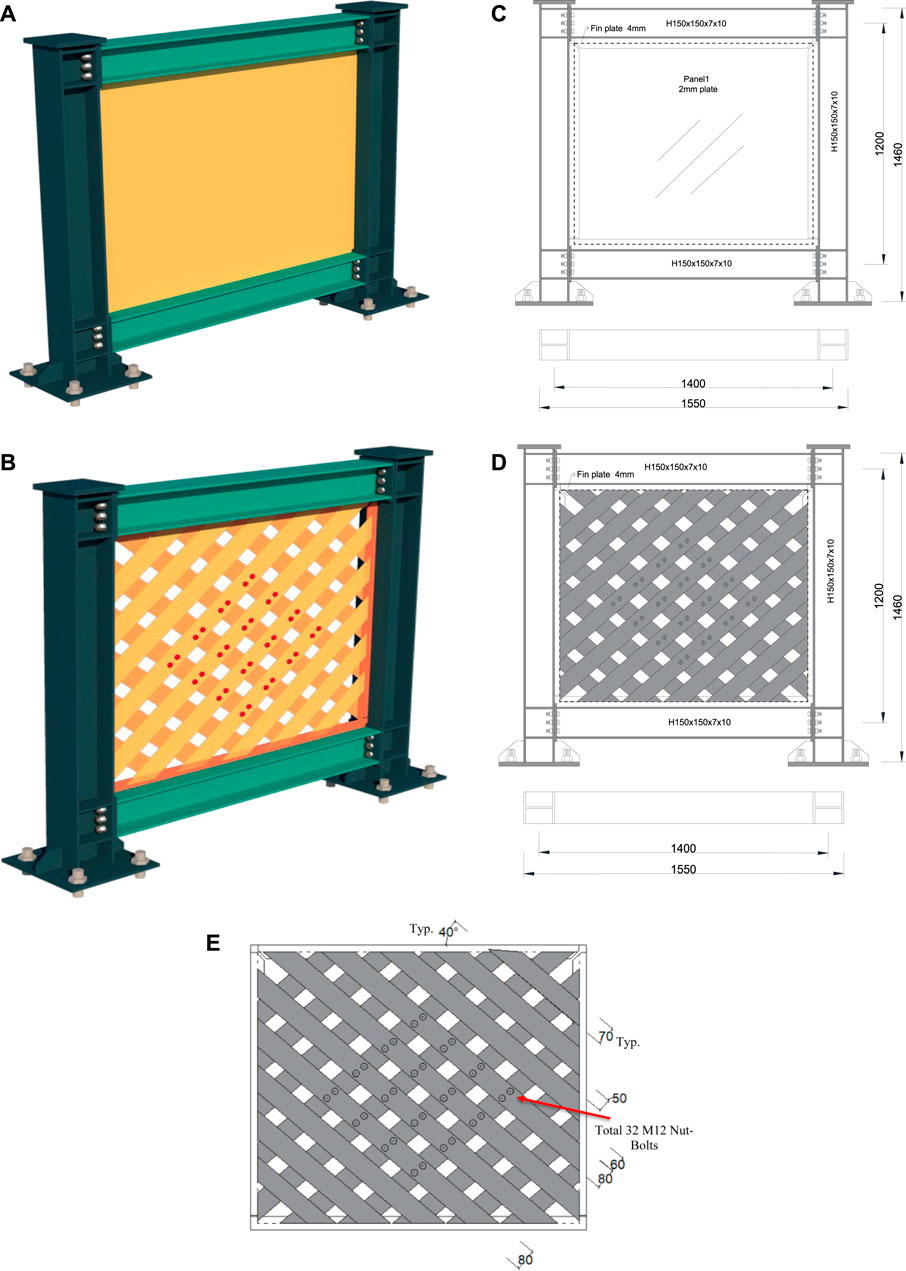
FIGURE 1. Geometric sketch of specimens (unit: mm): (A) Isometric view of USPSW; (B) Isometric of IWS-SPSW; (C) Front and Top -view of USPSW; (D) Front and Top view of IWS-SPSW; (E) Infill strips configurations and spacing.
Furthermore, as is seen in Figure 1E, the strip widths are not uniform. Strips come in two widths, the standard 70 mm, and the wider 80 mm. Because a strip cannot be delivered in perfect alignment with the connection joints, the width of the strips installed close to the beam-to-column joints was increased. The details of the essential parameters of the specimens are listed in Table 1.
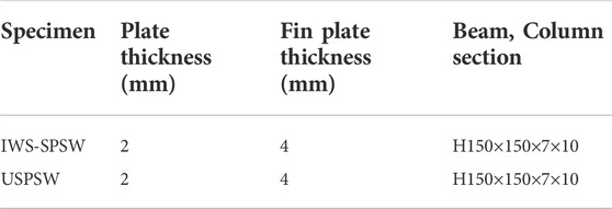
TABLE 1. Details of important parameters of the specimens.
2.1.1 Semi-rigid beam-to-column connections
In the SPSWs system, mainly two types of beam-to-column connections were recommended (AISC, 2016); fully rigid and partially rigid or semi-rigid beam-to-column connections. The previous study of USPSW by (Driver et al., 1998) with a fully rigid beam-to-column connection shows a significant increase in the energy dissipation of the system. Still, a fully rigid creates more concentration stress in the beam-column panel zone and nearby, which causes the beam-column connection to fracture. This study utilized the semi-rigid end-plate beam-to-column for both USPSW and IWS-SPSW, and this type of connection works as a dissipative energy zone, and it can prevent the HBEs and VBEs from earlier failure and fractures. Figure 2 represents the type of semi-rigid beam-to-column connections of the specimens. In the link of the semi-rigid beam-to-column, the beam web and flanges were welded to an end-plate, and M16 high-strength bolts were used to connect it to the column flange. The column bottoms were welded to the base plate with additional stiffeners. Table 2 provides complete details of the beam-column and base-plate connection components.
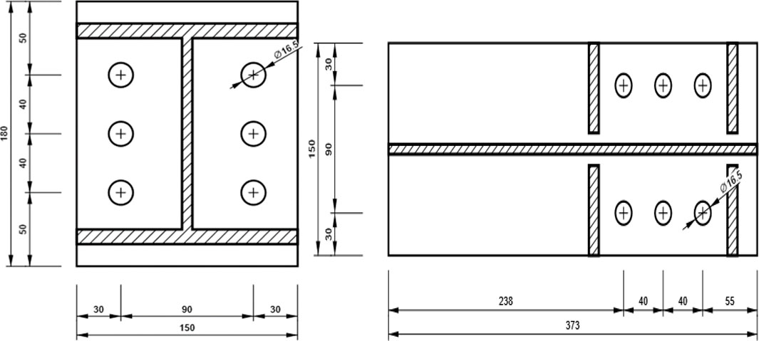
FIGURE 2. Semi-rigid beam-column connection properties (unit: mm).
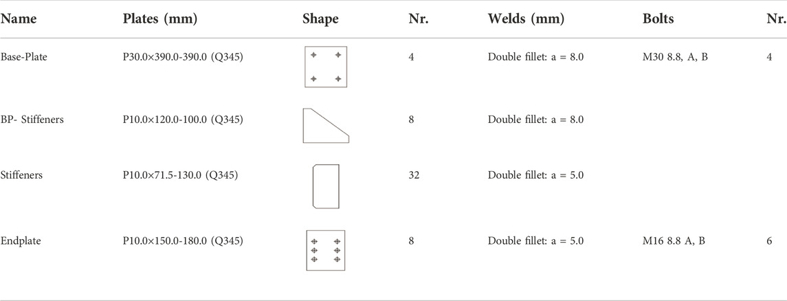
TABLE 2. Semi-rigid beam-columns and base-plate connection properties.
Figure 3 shows the web plate assembly and infill web strips connected to the boundary beam columns. First, a 4-mm-thick fin plate was welded to the beam columns; then, the web plate and infill strips were welded to the fin plate. In the end, the full-penetration groove and double fillet welding processes were carried out utilizing the electrode type E43. Coupon testing was conducted on two steel groups from the original material used to create the specimens. Table 3 lists the steel materials’ mechanical properties.
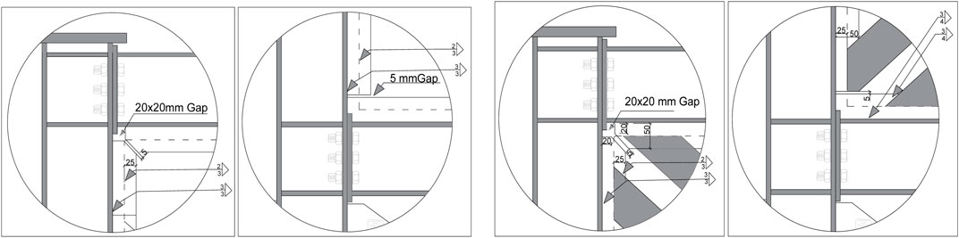
FIGURE 3. Connection details of web plates and infill web strips to beam columns (unit: mm).
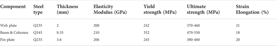
TABLE 3. Shows the steel materials' mechanical properties.
2.2 Test configuration
Figure 4A,B provides a visual representation of the test photo and configurations, including the loading mechanism and the boundary conditions. A singular hydraulic actuator was utilized to apply the lateral loads to one side of the top floor beam. A top beam was subjected to a vertical force of 200 kN, then transmitted to the columns below. A lateral support structure was also employed to limit the specimens’ potential for out-of-plane deformation. IWS-SPSW and USPSW specimens were tested at the “Yunnan Earthquake Engineering Research Institute” (YEERI). Different measuring tools, such as strain gauge, LVDT, and LC, were used to measure structure displacements, forces, and stresses.
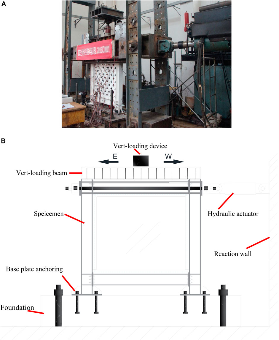
FIGURE 4. IWS-SPSW Test setup photo and configurations: (A) IWS-SPSW Test setup photo, (B) Test setup configurations.
2.3 Cyclic and gravity loading protocol
A full gravity force of roughly 100 kN was applied at the top of each column before any lateral weights were applied. This load was held steady right up until the final cycles. The specimens were laterally loaded in a cyclic quasi-static experiment employing a displacement control technique. The loading method recommended by the “Applied Technology Council ATC-24” was implemented (Krawinkler, 1992). The loading displacement history of the test specimens is shown in Figure 5. It offers an incremental rise in the number of deformation cycles. The loading steps started at 1.35 mm, and displacements grew to 54 mm. Note: “The drift in Figure 5 is calculated based on the maximum roof displacement divided by wall height (
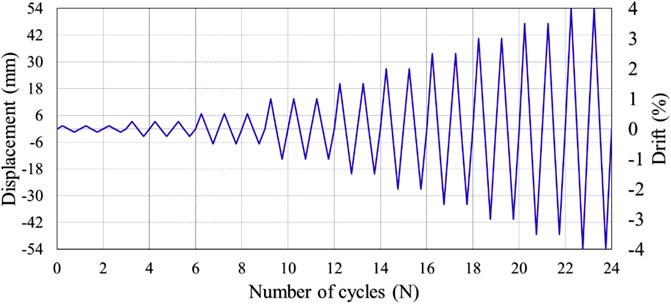
FIGURE 5. Applied loading pattern.
3 Test results and failure modes
The previous section used cyclic loading amplitudes to investigate the “IWS-SPSW and USPSW specimens” in a quasi-static configuration. The results of the SPSW experimental model are given in the following section. The evaluated effects include cyclic response, the hysteresis envelope, ductility characteristics, stiffness deterioration, energy dissipation capacity, and the failure modes mechanism.
3.1 The USPSW specimen’s cyclic behavior
During the first and second step loading cycles, the infill-web plate showed no buckling or yielding. In cycle seven’s third step, the infill plate initially yielded, and the web plate started to buckle. The displacement measured 6.75 mm (0.5% drift), corresponding to a shear force of 250 kN. The eighth and ninth cycles elicited the same response from the specimen as cycle seven, and buckling developed on the infill web plate. Throughout loading cycles 10, 11, and 12, the yielding and buckling wave of the infill web plate continued to increase. Infill web plate distortion, whitewash flaking, and column yielding were all observed at loading cycles 13 and 14. The horizontal deformation and corresponding shear forces in cycle 14 were 20.25 mm (1.5% drift) and 415.6 kN. As the force grew, there was noticeable bulging and buckling on the web plate and a loud sound. When the displacement reaches 27 mm (2.0% drift), the web plate corner tearing begins and gradually extends. Significant wrinkles were observed at the bottom of the columns when the displacement came to 33.75 mm (2.5% drift). The beam-column joint connection deformed slightly when the displacement reached 40.5 mm (3.0% drift), and the maximum load-bearing came to 510.4 kN. After the first cycle, the specimen failed by tearing the web plate corners when the displacement reached 47.2 mm (3.5% drift). The most significant out-of-plane displacement reached 42.62 mm in the final loading step, and the test was terminated. Figure 6 demonstrates the USPSW failure behavior.
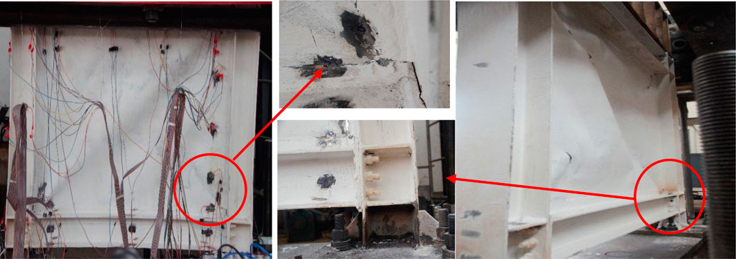
FIGURE 6. Failure phenomenon of USPSW specimen.
3.2 The IWS-SPSW specimen’s cyclic behavior
There was no remarkable phenomenon with the specimen until the drift ratio reached 1.5%. When the drift ratio hit 1.5%, a slight bulging deformation was seen, along with some noise from the infill web strips. As the load continued to increase, the infill web strips buckled all over and began to show clear signs of bulging. At the same time, a loud sound was produced. The beam-column joints gradually started deforming when the drift ratio was 2.0%. When the loading increased to 2.5% drift, the columns showed bending and wrinkling at the bottom. When the drift ratio reached 3.0%, the plastic hinges appeared at the bottom of the columns, and significant out-of-plane bucklings were observed on the infill web strips. The same occurrence was seen until the 4.0% drift ratio; no tearing or fractures were observed in the specimen. The maximum out-of-plane infill-strips deformation in the center, which had a nut-bolt connection, measured 35 mm, and the boundary reached 75.0 mm in the last loading step. The loading stopped because of significant infill web strips, out-of-plane buckling, and column bendings. Figure 7 illustrates the failure modes and cyclic response of IWS-SPSW.
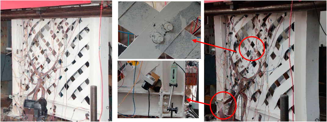
FIGURE 7. The IWS-SPSW specimen failure phenomenon.
3.3 Hysteresis behavior of the specimens
The two experiments’ force-displacement hysteresis curves were drawn (Figure 8). Both specimens displayed great flexibility and desirable behavior under lateral loads. The maximum lateral displacement in the USPSW and ISW-SPSW specimens was measured at 47.25 mm (corresponding to a drift ratio of about 3.5%) and 54 mm (corresponding to a drift ratio of about 4%). Overall excellent stability of the hysteresis response can be observed in the IWS-SPSW specimen, which indicates a ductile behavior under the cyclic loading test. Moreover, the lateral displacement and drift ratio of IWS-SPSW was higher than the USPSW, showing more lateral deformation capacity.
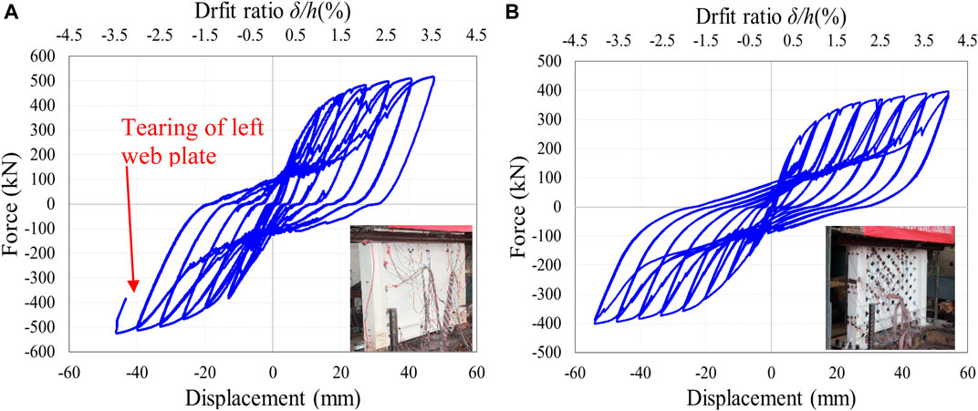
FIGURE 8. Hysteresis loop of (A) USPSW and (B) IWS-SPSW.
3.4 Skeleton curve of the specimens
The skeleton curve was drawn by combining the peak points of the first loading cycle for each specimen using the hysteretic curves. Both specimens’ smooth S-shaped skeleton curves indicate that the loading mechanism includes the elastic, elastic-plastic, and rupture stages, as shown in Figure 9. The ultimate shear and yield strength for the two test specimens are listed in Table 4. It could be deduced that the two specimens’ positive and negative bearing capacities differed only slightly, reflecting the symmetry of the specimens’ shear performance in both directions. The bi-diagonal infill strips significantly affected the initial stiffness of spacemen while creating greater flexibility. At the desired lateral drift ratio, no reduction in shear bearing capacity was observed at 4 percent drift.
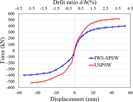
FIGURE 9. Comparison of skeleton curves.
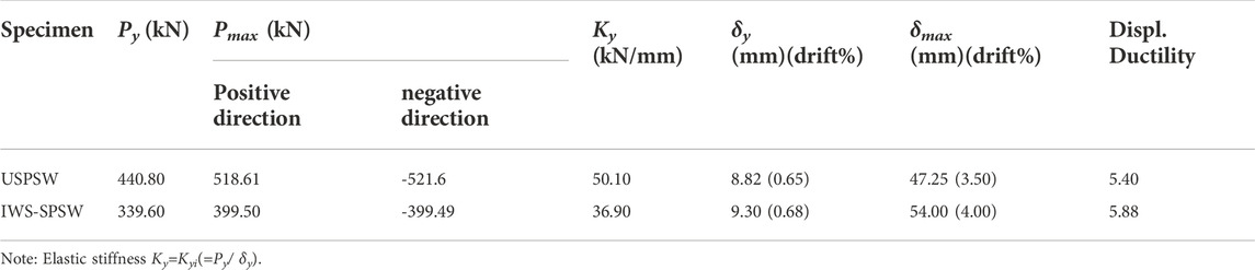
TABLE 4. Summary of the test results.
3.5 Initial stiffness and stiffness deterioration
When drawing an idealistic elastoplastic (IEP) envelope curve, equal amounts of plastic energy are used Park et al. (2007). The yield point is determined by comparing the region covered by the test envelope to the IEP curve, as shown in Figure 10. Figure 11 depicts the IEP curve and the load-displacement envelope curve derived from the test specimen’s findings. The initial stiffness of specimens, denoted by the symbol (Kyi), is determined by utilizing the IEP curve and calculating the force ratio to the displacement of the elastic area. According to Table 4, “the initial stiffness of USPSW and IWS-SPSW specimens were estimated at 50.10 and 36.90 kN/mm, respectively.” Figure 13A shows that the stiffness secant describes the specimens’ stiffness degradation.
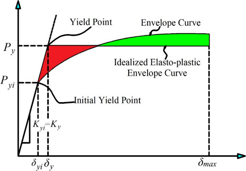
FIGURE 10. Yield point and initial yield point definitions.
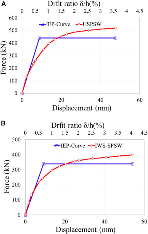
FIGURE 11. The test specimen's envelope and IEP curves: (A) USPSW; (B) IWS-SPSW.
The stiffness secant is obtained from an envelope curve and is equal to the line gradient that passes between points (δi, Pi); and (0,0); as the specimen’s displacement increases, the specimen’s stiffness reduces.
3.6 The specimens’ displacement ductility
The displacement ductility (μ) is demonstrated as the maximum relative lateral dis-placement (δmax) to the maximum relative lateral displacement at the yield point (δy), or (μ = δmax/δy) shown in Figure 10. Table 4 presents the computed ductility values for the various specimens. The “ductility-characterized values of the USPSW and IWS-SPSW were 5.40 and 5.88, respectively”. Both specimens’ yield point (δy) was approximately 0.65% and 0.68% drift (8.82 and 9.30 mm). In comparsion, the IWS-SPSW exhibit higher ductility than the USPSW specimen.
3.7 Energy dissipation capacity of the specimens
Figure 12 represents the area under the hysteresis loop, which can be used to calculate the energy dissipation capacities of this system (Gorji Azandariani et al., 2020). The two-step cyclic loading is in the elastic region, where the minimum energy dissipated capacity is shown. The IWS-SPSW specimen dissipated approximately the same energy as the USPSW until 1% drift. As indicated in Figure 13B, the energy dissipation capability of the specimens has risen with increasing loading steps. From general loading steps, the impact of the web plate’s energy dissipation performance, particularly in the plasticity region, is more significant than that of Infill web strips. In the USPSW specimen cycle 22nd, the maximum cumulative energy dissipation was 75.25 kJ, accounting for more than 43% of the IWS-SPSW 42.7 kJ. The IWS-SPSW resists more deformation than the USPSW, which causes to dissipate of more energies in the late loading cycle, and the cumulative energy is measured at 59.30 kJ.
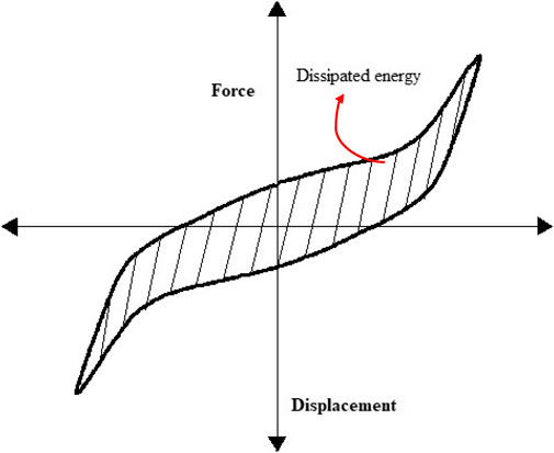
FIGURE 12. Method for calculating the energy dissipation capacity of a hysteresis curve.
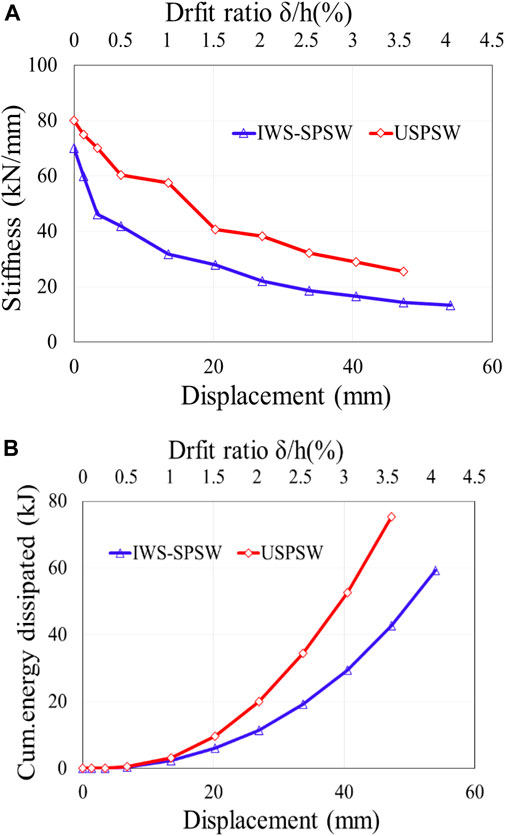
FIGURE 13. (A) Stiffness degradation, (B) cumulative energy dissipation.
4 Numerical simulation of the proposed shear wall
The nonlinear FE models for the USPSW and the IWS-SPSW were built in the commercial software ABAQUS. Large-strain formulations and reduced integration were used to model the complete specimen as four-node quadrilateral stress/displacement shell components (ABAQUS S4R Element) Abaqus (2022). Because we wanted to keep the shell models as straightforward as possible, we did not include any of the fin plates. Direct connections were made between the infill panels and the HBEs and VBEs. For the end-plate beam-column links, a method is used to define the nut bolts shown in Figure 14, the circular beam profile corresponding to the bolt shank, and two MPCs (Multi Point Constraints) were created to connect each endpoint of the end-plates to the joint members.
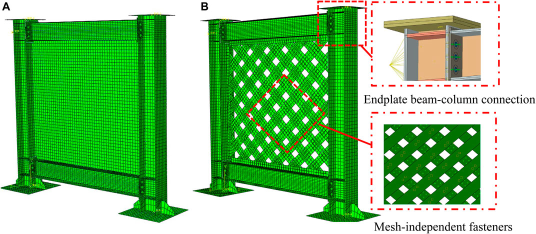
FIGURE 14. FE model of (A) USPSW and (B) IWS-SPSW.
Based on a mesh-independent fastener, the bolt connection of infill web strips was specified by (Abaqus, 2022). Both VBEs were secured to their respective base plates, the bottom constraint was fixed on the base plate, and the out-of-plane regulations were similar to earlier experimental tests. The loading pattern consists of two stages: the first stage involves vertical loads, while the second stage involves horizontal cyclic displacements. Figure 14A,B represents the FE models of the specimens. Given the FE models’ high levels of accuracy and efficiency, it was decided to perform a sensitivity analysis for the dimensions and element type. The mesh used in the FE models can significantly impact the accuracy of its results. Using a mesh refinement of 25 × 25 mm, the finite-element models’ results reasonably agreed with those of the experiments. In order to model the buckling of infill plates, an eigenvalue buckling analysis was used to estimate the mode forms of the plates. The magnitude of the fundamental imperfection was restricted to
It is possible to derive the parameters of the hardening-combined constitutive model through data fitting Wang et al. (2015b). Table 5 presents the hardening-combined properties of the steels Q235 and Q345, respectively. However, analyzing a thin steel plate shear wall subjected to cyclic loadings exhibits complex nonlinear behaviors. These behaviors include panel buckling, local buckling of columns, sizeable out-of-plane deformation, and bidirectional tension strips. The “ABAQUS dynamic implicit solver for a quasi-static based on the central difference time-stepping solution technique for incremental displacement is used to perform these analyses Abaqus (2022).”
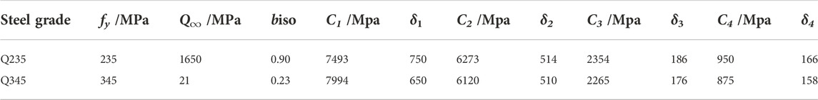
TABLE 5. Parameters of the cyclic constitutive models.
5 The validation of FE models
The FE models and experimental data were compared to verify the validity of numerical simulations regarding the specimens’ hysteresis loops, envelope curves, and failure mechanisms. The hysteresis loop under the quasi-static cyclic loading manner and the corresponding envelope curves of analysis and test results are shown in Figure 15; Figure 16A,B. The analysis slightly underestimated the initial stiffness of the USPSW and IWS-SPSW specimens because of the slip in the loading frame and its connection to the actuator. Despite this, the analysis’s maximum loads accord with the test results. The suggested FE analysis model accurately reflects the specimens’ hysteresis loop, including buckling and pinching phenomena. Figure 17A,B compare the failure mechanisms of specimens based on the Von-mises stress variations, respectively, obtained from the FE model analysis and test results.
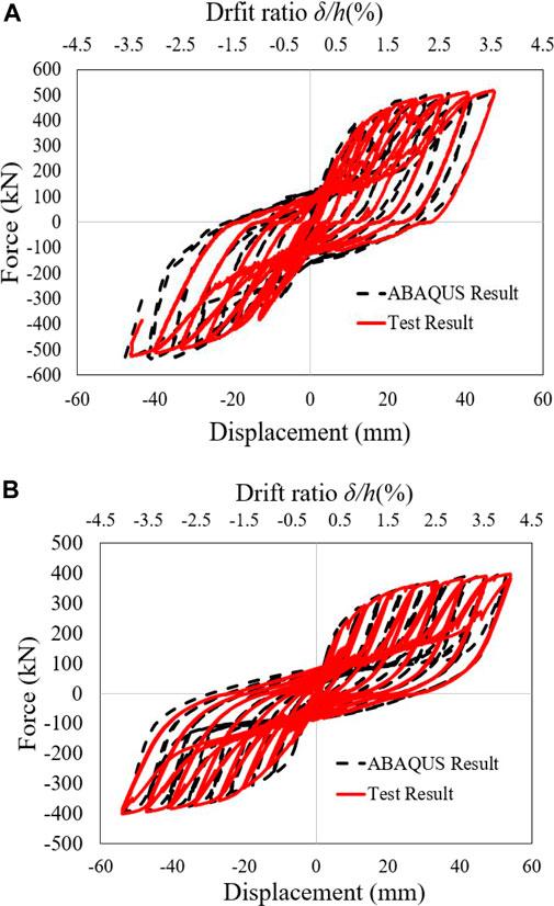
FIGURE 15. The hysteresis comparsion curves: (A) USPSW, and (B) IWS-SPSW specimen.
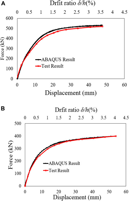
FIGURE 16. Envelope curves comparison: (A) USPSW, and (B) IWS-SPSW specimen.
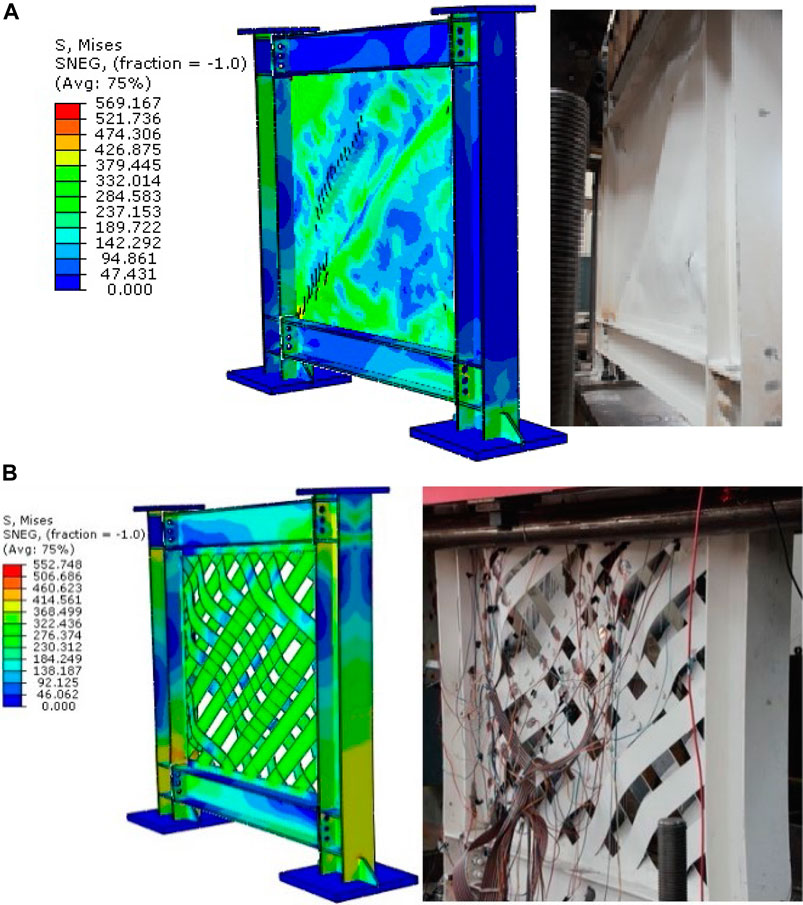
FIGURE 17. Comparison of failure mode: (A) USPSW, and (B) IWS-SPSWspeciemen.
5.1 Numerical analysis of the frame with and without infill panel
The FE model of the frame was modeled without the panel and analyzed under cyclic and pushover analysis to investigate the contribution of infill strips and panels in the steel shear walls system. Figure 18A shows the steel frame without panels, as same as the SPSW boundary condition, and the loading was used for the frame without panels in the FE model analysis. The hysteresis curve of the frame is shown in Figure 18B; The hysteresis loops start to open during the 16.85.25 mm (1.35% drift) cycle. The nonlinear response of the frame was initiated after a horizontal pulling load of 43.94 kN was applied. The first plastic hinge is formed at the end of the beams at a displacement of 41.5 mm. Figure 18C,D shows a pushover curve of the frame with and without infill panels; from the pushover curve, the yield and ultimate strength of the frame were calculated.
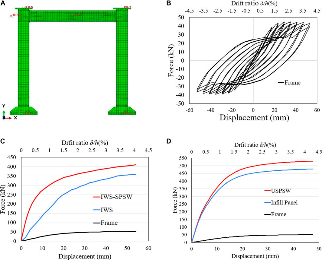
FIGURE 18. Cyclic and pushover response of frame with and without infill strips and infill panel: (A) FE model of the frame without infill panel, (B) hysteresis loops of the frame, (C) frame contribution in the IWS-SPSW, (D) frame contribution in the USPSW.
Additionally, the ductility and initial stiffness of the frame were determined and presented in Table 6. The frame contributed approximately 25% of the structure’s load bearing in the IWS-SPSW, and the infill strips generated 75% of resisting shear forces. Moreover, the frame shear force contributed approximately 12% of the USPSW and 88% shear force generated by the infill panel.
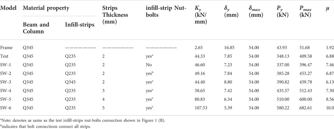
TABLE 6. The models' parametric analysis and the results of those investigations.
6 Parametric study
This parametric investigation tested six configurations of infill-web strip thickness, infill web-strip connections, and material yield strengths on one-story IWS-SPSW models. Table 6 summarizes and fully describes the mechanical properties of the materials used in the IWS-SPSW models that are the research focus. The simulation of the displacement-controlled type was utilized in place of the identical specimen for testing with cyclic loading. Table 6 presents the parametric analysis performed on the numerical models. The results of the computations are shown in Table 6, which includes the values for initial stiffness, yield shear strength, ultimate shear strength, yield displacement, and ductility coefficient. Additionally, Table 6 provides the suggested abbreviations for parametric models. “1) Infill web-strips steel plate shear wall without preventing large strips buckling bolt connections (SW-1). 2) Infill web-strips steel plate shear walls with all strips are prevented from significant elastic buckling by nut-bolt connections (SW-2). 3) Infill web-strips steel plate shear wall with the same boundary element and infill plate material (SW-3). 4) Infill web-strips steel plate shear wall with infill strips thickness of 3, 4 and 5 mm (SW-4, SW-5, and SW-6), respectively.”
6.1 Impact of the infill-strip nut bolt connections
According to the information presented in Table 6, a total of three models (Test, SW-1, and SW-2) were considered. On each of the models, lateral cyclic and pushover analyses were carried out so that the effects of the infill web-strips bolt connection on the inelastic response of the system could be studied.
The hysteresis, pushover, and “Idealized Elastic to Plastic (IEP) curves” of the three FE models are depicted in Figure 19A-D. The first parametric model (test specimen’s) stiffness, load-bearing, and post-buckling with initial stiffness of 44.33 kN/mm, and 348.13,409.58 kN yield, ultimate base shear, and a maximum strip deformation of 71.5 mm were measured. The SW-1 parametric model without web-strip nut bolt connections exhibited 46.60 kN/mm initial stiffness and 337.28, 396.47 kN yield and ultimate base shear. The maximum strip deformation was 107.2 mm at the loading end. Initial stiffness was found to be 49.16 kN/mm in the SW-2 parametric model with complete bi-diagonal strips bolt connections, with yield and ultimate base shear values of 385.28, 453.27 kN and ultimate base shear values of 453.33 kN correspondingly from the inelastic response finding. After the loading investigation, 49.4 mm of infill web-strip deformation was measured. Compared to the other three FE models, the SW-2 performed admirably and showed high strength and ductility. The Von-Mises stress and post-buckling behavior of the three models are shown in Figure 20A-C.
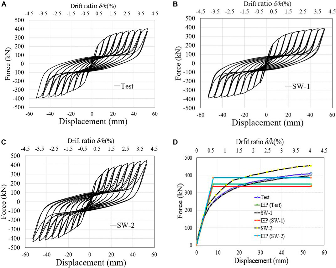
FIGURE 19. Hysteresis, skeleton, and IEP curves of FE model: (A–C) Hysteresis, (D) Pushover, and IEP curves.
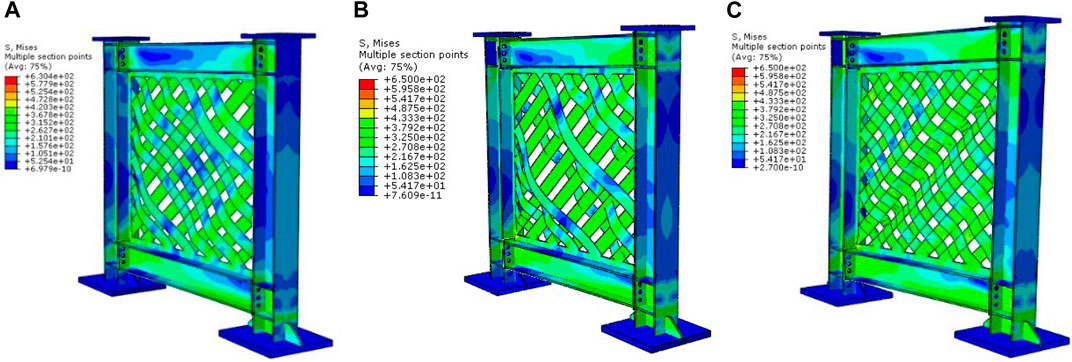
FIGURE 20. The Von-Mises stress and the post-buckling response of the parametric models: (A) Test, (B) SW-1, and (C) SW-2 model.
6.2 Impact of the infill web-strips material yield stress
Figure 21A-B displays the hysteresis, pushover, and “Idealized Elastic-to plastic (IEP) curves” of the SW-3 parametric model with a high infill web-strips steel yield strength; the inelastic response of the model was shown to have an initial stiffness of 44.40kN/and a yield and ultimate shear force of 390.82 and 459.78kN, respectively. Compared to the prior parametric models, a significant improvement in load-bearing capacity was achieved, while a reduction in displacement ductility was acquired. Because of this, the impact of the material’s yield strength on the load-bearing capacity can be considered accountable. The Von-Mises stress, deformation, and post-buckling behavior of model SW-3 are depicted in Figure 22. In addition to this, the joint between the beam and the column experienced severe deformations.
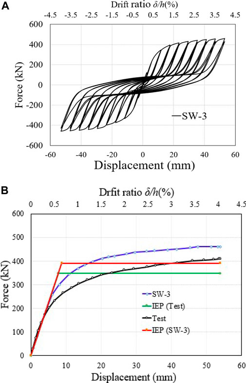
FIGURE 21. Hysteresis, pushover, and IEP curves of the FE model: (A) Hysteresis, (B) pushover, and IEP curves.
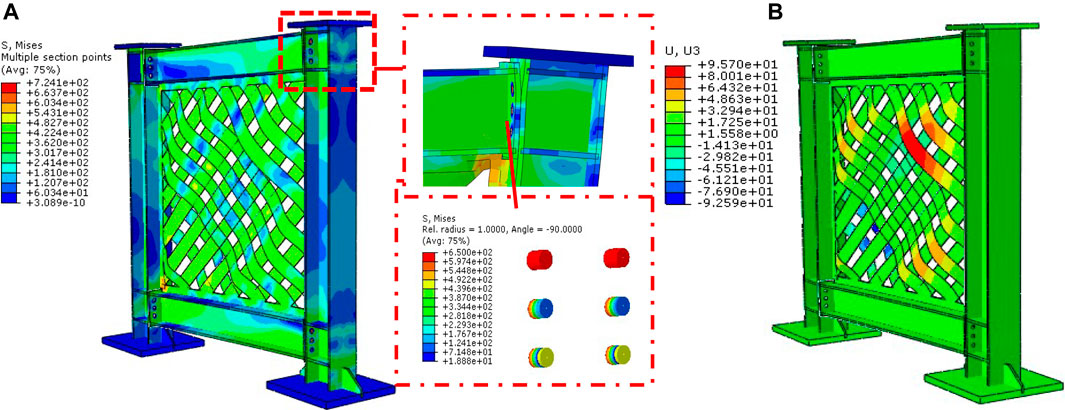
FIGURE 22. Von-Mises stress and post-buckling behavior of the parametric model, SW-3: (A) Von-Mises stress, and (B) Deformation.
6.3 Impact of infill web-strip thickness
Figure 23A-D hysteresis behavior, pushover, and Idealized Elastic to Plastic (IEP) curves are defined for the SW-4 through SW-6 parametric models. Different infill web-strips plate thicknesses were examined across three models (SW-4-5-6), all of which shared the same wall plate width and vertical and horizontal loading conditions. The SW-4 model with a thickness of 3 mm for its infill web strips showed an initial stiffness of 58.65 kN/mm and a yield and ultimate base shear of 435.57 and 512.43 kN, respectively. A yield and ultimate base shear force of 510,600 kN and 80.83 kN/mm were observed in the SW-5 model with a web-strip thickness of 4 mm. The SW-5 simulation found an in-plane column failure at the base. Therefore, after a lateral drift of 3.5%, there was a minor decline in both the hysteresis and envelope curves.
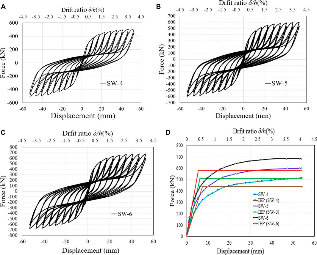
FIGURE 23. The FE model's hysteresis, pushover, and IEP curves are (A–C) Hysteresis, (D) Pushover, and IEP curves.
The SW-6 model with a web-strip thickness of 5 mm demonstrated an initial stiffness of 107.53 (kN/mm), yield, and ultimate base shear loads of 580.22 and 682.61 kN, respectively. The SW-6 model offered the same behavior as SW-5, with higher column bending deformations and significant beam-column joint damage. The analysis of three models with thicknesses of 2, 3, and 4 mm has shown remarkable performance in load-carrying capacity, ductility, and initial stiffness. The model with more significant than a 4 mm thickness has a high load-carrying capacity, ductility, and initial stiffness. But an extensive bending and axial force can be transformed to the beam columns, which will cause significant beam-column joint damage and plastic hinge deformations. Figure 24A-C illustrates the aforementioned parametric models’ Von-Mises stress and post-buckling behavior.
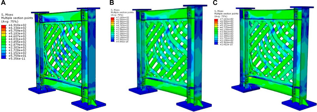
FIGURE 24. The Von-Mises stress and the post-buckling response of the parametric models: (A) SW-4, (B) SW-5, and (C) SW-6.
7 Conclusion
This article presents the results of an experimental and numerical investigation comparing the performance of a “novel infill web-strips steel plate shear wall (IWS-SPSW) to that of a regular, unstiffened steel plate shear wall (USPSW).” Under cyclic loading conditions, two 1:3 scale single-story SPSW specimens were built and analyzed. The nonlinear FE model of each specimen was developed and verified based on the results of the tests. Nonlinearities in materials and geometry, as well as large deformations and imperfections in geometry, were all considered in the FE models. A “parametric analysis was performed to determine the impact of the bolt connection of bi-diagonal strips, the yield stress of the infill web strips, and infill web-strips thickness.” Finally, the following significant points are highlighted:
• SPSWs specimens showed good shear load bearing, deformation, energy dissipation, and ductility. USPSW has a 5.40 displacement ductility factor, while IWS-SPSW has a 5.88. The ISW-SPSW displayed approximately 23.5% less yield and the ultimate load. The stress concentration at the USPSW web plate corners was also caused to tear after a 2% story drift ratio. This issue was not observed in the IW-SPSW specimen. Both specimens exhibited excellent energy dissipation. The end-plate beam-to-column connection was vital; “no fracture or tearing was observed in the joint connectors and panel zones.”
• In The USPSW infill web plate, significant cracks were observed; those cracks in the corners of the plate caused wide fractures, and finally, the specimen lost the load-bearing capacity and did not take more deformations. But the IWS-SPSW resisted more deformation till 4% story drift, and no significant cracks and fractures were observed.
• By comparing the hysteresis loops with experimental results determined that the numerical model could accurately show the buckling and post-buckling phenomena and load-bearing capacity under cyclic loading. The FE simulated models reasonably accurately reproduced the infill web plate tensile field, out-of-plane deformation, the specimen’s stiffness, and pinching effects. It was found that FE models could more accurately estimate the probability of SPSW failure modes based on the Von-mises stress and post-buckling deformation results.
• The FE model of the steel frame was developed as a baseline, and the contribution of the frame to the shear walls test was investigated. The frame hysteresis shows an ultimate force of 51.63 kN, indicating a 25% overall IWS-SPSW and 12% of the USPSW maximum shear force.
• The parametric investigation revealed that “the bolt connection of bi-diagonal strips, the yield stress of the infill web strips, and the thickness of the infill web strips all have substantial effects on the shear load-bearing and out-of-plane buckling of the IWS-SPSWs. After investigation, it was discovered that the SW-3, SW-4, and SW-5 showed the best performance.” IWS-SPSW, with thicker infill strips and bi-diagonal infill strip connections, can provide a novel lateral load-resisting steel shear wall system. Moreover, the length to height and the type of connection of infill strips to the boundary elements can impact the system’s overall seismic performance; therefore, recommended for future study.
Data availability statement
The original contributions presented in the study are included in the article/Supplementary Material, further inquiries can be directed to the corresponding authors.
Author contributions
WG: methodology, writing—review and editing, software, validation. TZ: conceptual-ization, investigation, funding acquisition. MA: writing—review and editing. EF: formal analysis. AM: project administration. AY: investigation, resources.
Funding
This research is supported by the Key Research and Development programs (Key R and D programs) department of science and technology of Yunnan province (Grant nos. 202003AC100001).
Conflict of interest
The authors declare that the research was conducted in the absence of any commercial or financial relationships that could be construed as a potential conflict of interest.
Publisher’s note
All claims expressed in this article are solely those of the authors and do not necessarily represent those of their affiliated organizations, or those of the publisher, the editors and the reviewers. Any product that may be evaluated in this article, or claim that may be made by its manufacturer, is not guaranteed or endorsed by the publisher.
References
Abdul Ghafar, W., Tao, Z., Tao, Y., He, Y., Wu, L., and Zhang, Z. (2022). Experimental and numerical study of an innovative infill web-strips steel plate shear wall with rigid beam-to-column connections. Buildings 12 (10), 1560. doi:10.3390/buildings12101560
AISC (2016). Seismic provisions for structural steel buildings, ANSI/AISC 341-16. Chicago, IL: American Institute for Steel Construction.
Berman, J. W., Celik, O. C., and Bruneau, M. (2005). Comparing hysteretic behavior of light-gauge, steel plate shear walls and braced frames. Eng. Struct. 27 (3), 475–485. doi:10.1016/j.engstruct.2004.11.007
Choi, I-R., and Park, H-G. (2009). Steel Plate shear walls with various infill plate designs. J. Struct. Eng. (N. Y. N. Y). 135 (7), 785–796. doi:10.1061/(asce)0733-9445(2009)135:7(785)
Dou, C., Cheng, X., Zhao, Y-Y., and Yang, N. (2021). Shear resistance and design of infill panels in corrugated-plate shear walls. J. Struct. Eng. (N. Y. N. Y). 147 (11), 04021179. doi:10.1061/(asce)st.1943-541x.0003162
Driver, R. G., Kulak, G. L., Kennedy, D. L., and Elwi, A. E. (1998). Cyclic test of four-story steel plate shear wall. J. Struct. Eng. (N. Y. N. Y). 124 (2), 112–120. doi:10.1061/(asce)0733-9445(1998)124:2(112)
Gorji Azandariani, M., Gholhaki, M., and Kafi, M. A. (2020). Experimental and numerical investigation of low-yield-strength (LYS) steel plate shear walls under cyclic loading. Eng. Struct. 203, 109866. doi:10.1016/j.engstruct.2019.109866
Haji Mirsadeghi, M. R., and Fanaie, N. (2021). Steel plate shear walls with partial length connection to vertical boundary element. Structures 32, 1820–1838. doi:10.1016/j.istruc.2021.02.003
Hajimirsadeghi, M. R., and Fanaie, N. (2021). Steel plate shear walls with large disconnected lengths of web plate to vertical boundary element. Structures 34, 4596–4615. doi:10.1016/j.istruc.2021.10.056
Hou, J., Guo, L., and Yan, J. (2021). Steel plate–restraining panel interaction behavior in buckling-restrained steel plate shear walls. Thin-Walled Struct. 169, 108348. doi:10.1016/j.tws.2021.108348
Jin, S., Du, H., and Bai, J. (2021). Seismic performance assessment of steel frame structures equipped with buckling-restrained slotted steel plate shear walls. J. Constr. Steel Res. 182, 106699. doi:10.1016/j.jcsr.2021.106699
Khalilzadehtabrizi, S., Seifiasl, A., and Hoseinzadeh Asl, M. (2021). Measurement of deformation patterns in steel plate shear walls subjected to cyclic loading based on multi-target digital image correlation (MT-DIC). Structures 33, 2611–2627. doi:10.1016/j.istruc.2021.06.007
Khaloo, A., Ghamari, A., and Foroutani, M. (2021). On the design of stiffened steel plate shear wall with diagonal stiffeners considering the crack effect. Structures 31, 828–841. doi:10.1016/j.istruc.2021.02.027
Kim, J. M., Varma, A., Seo, J., Bruhl, J., Lee, K., and Kim, K. (2021). Steel-Plate composite walls subjected to missile impact: Experimental evaluation of local damage. J. Struct. Eng. (N. Y. N. Y). 147 (2), 04020312. doi:10.1061/(asce)st.1943-541x.0002806
Kordzangeneh, G., Showkati, H., Rezaeian, A., and Yekrangnia, M. (2021). Experimental cyclic performance of steel shear walls with single rectangular opening. Struct. Des. Tall Spec. Build. 30 (2). doi:10.1002/tal.1821
Krawinkler, H. (1992). ATC-24: Guidelines for cyclic seismic testing of components of steel structures. Redwood City: Report prepared for the Applied Technology Council.
Li, C-H., Tsai, K-C., Lin, C-H., and Chen, P. C. (2009). Cyclic tests of four two-story narrow steel plate shear walls. Part 2: Experimental results and design implications. Earthq. Eng. Struct. Dyn. 39 (7), 801–826. doi:10.1002/eqe.964
Lu, J. Y., Yu, S. J., Xia, J., Qiao, X., and Tang, Y. (2018). Experimental study on the hysteretic behavior of steel plate shear wall with unequal length slits. J. Constr. Steel Res. 147, 477–487. doi:10.1016/j.jcsr.2018.05.002
Meng, B., Hao, J., and Zhong, W. (2021). Numerical study on the anti-progressive collapse performance of steel frame-steel plate shear wall structures. J. Build. Eng. 35, 102049. doi:10.1016/j.jobe.2020.102049
Ozcelik, Y. (2021). Expeditious strip model for steel plate shear walls with beam-connected web plates. J. Constr. Steel Res. 184, 106799. doi:10.1016/j.jcsr.2021.106799
Park, H-G., Kwack, J-H., Jeon, S-W., Kim, W. K., and Choi, I. R. (2007). Framed steel plate wall behavior under cyclic lateral loading. J. Struct. Eng. (N. Y. N. Y). 133 (3), 378–388. doi:10.1061/(asce)0733-9445(2007)133:3(378)
Qing, Y., Wang, C-L., Meng, S., and Zeng, B. (2022). Experimental study on the seismic performance of precast concrete columns with thread-bolt combination couplers. Eng. Struct. 251, 113461. doi:10.1016/j.engstruct.2021.113461
Sarcheshmehpour, M., Shabanlou, M., Meghdadi, Z., Estekanchi, H., and Mofid, M. (2021). Seismic evaluation of steel plate shear wall systems considering soil-structure interaction. Soil Dyn. Earthq. Eng. 145, 106738. doi:10.1016/j.soildyn.2021.106738
Shen, J., Groh, R. M. J., Wadee, M. A., Schenk, M., and Pirrera, A. (2022). Probing the stability landscape of prestressed stayed columns susceptible to mode interaction. Eng. Struct. 251, 113465. doi:10.1016/j.engstruct.2021.113465
Shin, D-H., and Kim, H-J. (2022). Post-buckling strengths of steel-plate shear walls with two-side clamped boundary conditions. Thin-Walled Struct. 170, 108499. doi:10.1016/j.tws.2021.108499
Tian, W., Ma, Y., and Berman, J. W. (2021). Uniform strip model of steel plate shear walls with different plate thicknesses. J. Struct. Eng. (N. Y. N. Y). 147 (11). doi:10.1061/(asce)st.1943-541x.0003134
Wang, M., Shi, Y. J., Xu, J., Yang, W., and Li, Y. (2015a). Experimental and numerical study of unstiffened steel plate shear wall structures. J. Constr. Steel Res. 112, 373–386. doi:10.1016/j.jcsr.2015.05.002
Wang, M., Yang, W., Shi, Y., and Xu, J. (2015b). Seismic behaviors of steel plate shear wall structures with construction details and materials. J. Constr. Steel Res. 107, 194–210. doi:10.1016/j.jcsr.2015.01.007
Wang M., M., Guo, Y., and Yang, L. (2021). Damage indices and fragility assessment of coupled low-yield-point steel plate shear walls. J. Build. Eng. 42, 103010. doi:10.1016/j.jobe.2021.103010
Wang, W., Luo, Q., Sun, Z., Wang, B., and Xu, S. (2021). Relation analysis between out-of-plane and in-plane failure of corrugated steel plate shear wall. Structures 29, 1522–1536. doi:10.1016/j.istruc.2020.12.030
Xu, L., Liu, J., and Li, Z. (2021). Parametric analysis and failure mode of steel plate shear wall with self-centering braces. Eng. Struct. 237, 112151. doi:10.1016/j.engstruct.2021.112151
Yang, X., Xu, L., and Pan, J. (2021). Mechanical behavior of full-scale composite steel plate shear wall restrained by ECC panels. J. Build. Eng. 44, 102864. doi:10.1016/j.jobe.2021.102864
Yu, J., Huang, J., Li, B., and Feng, X. (2021). Experimental study on steel plate shear walls with novel plate-frame connection. J. Constr. Steel Res. 180, 106601. doi:10.1016/j.jcsr.2021.106601
Yu, Y., Hu, C., Zhao, F., and Jiang, L. (2022). Research on the specially-shaped corrugated steel plate shear walls with horizontal corrugation. J. Constr. Steel Res. 188, 107012. doi:10.1016/j.jcsr.2021.107012
Keywords: steel shear walls, seismic performance, failure mode, hysteresis response, nonlinear finite element analysis, parametric study
Citation: Abdul Ghafar W, Zhong T, Abid M, Faizan E, Mohamed A and Yosri AM (2022) Seismic performance investigation of an innovative steel shear wall with semi-rigid beam-to-column connections. Front. Mater. 9:1075300. doi: 10.3389/fmats.2022.1075300
Received: 20 October 2022; Accepted: 14 November 2022;
Published: 01 December 2022.
Edited by:
Zhicheng Yang, Zhongkai University of Agriculture and Engineering, ChinaCopyright © 2022 Abdul Ghafar, Zhong, Abid, Faizan, Mohamed and Yosri. This is an open-access article distributed under the terms of the Creative Commons Attribution License (CC BY). The use, distribution or reproduction in other forums is permitted, provided the original author(s) and the copyright owner(s) are credited and that the original publication in this journal is cited, in accordance with accepted academic practice. No use, distribution or reproduction is permitted which does not comply with these terms.
*Correspondence: Tao Zhong, taozhong@kust.edu.cn; Muhammad Abid, abidkhg@gmail.com