Fatigue Behavior of Super Duplex Stainless Steel Exposed in Natural Seawater Under Cathodic Protection
 Flavien Vucko
 Geoffrey Ringot1
  Dominique Thierry
- 1French Corrosion Institute—RISE, Brest, France
- 2RISE Research Institute of Sweden, Kista, Sweden
Under operating conditions, alternated loading and fatigue are encountered, controlling the durability and safety of components and structures made of super duplex stainless steel (SDSS). In particular, the use of a cathodic protection (CP) system to protect the structure against corrosion can induce hydrogen charging of the SDSS. Thus, the aim of this study was to investigate the sensitivity of some industrial products made of SDSS 2507 (UNS S32750), without artificial thermal aging, under test conditions as close as possible to real environments. In situ fatigue tests under alternated 4-point bending conditions were conducted in natural seawater with and without CP. The fatigue behavior was evaluated as a function of environmental parameters, such as temperature, and material parameters, particularly the austenite spacing and microstructure around orbital welds by Tungsten Inert Gas (TIG) welding and stress concentrations, through the presence of surface defects. The fatigue life obtained in air or in seawater at the open circuit potential (OCP) was rather similar. Fatigue life enhancement was systematically observed under CP particularly in the range of low applied load, despite evidence of brittle failure on the fracture surfaces of samples tested under CP. The data suggest immunity of the SDSS to hydrogen embrittlement under the present experimental conditions of fatigue testing.
Introduction
Super duplex stainless steels (SDSSs) are widely used in offshore applications. They offer high strength, toughness, and excellent corrosion resistance. They are characterized by a mixed microstructure of austenite and ferrite in equal amount. SDSSs are often combined with carbon steel for offshore construction. They can, thus, be exposed to cathodic protection (CP), which is widely used for carbon steel offshore constructions. SDSS may also be protected by CP, for instance, where the operating temperature is above the maximum allowed temperature for the use of the alloys in seawater (Francis et al., 1997). A small decrease in the corrosion potential of SDSS is generally beneficial, limiting the risks of breakdown of the passivity of the stainless steels and the formation of anodic sites, for example, crevice. At the same time, cathodic polarization can activate water reduction reactions, generating hydrogen at the surface of the protected stainless steel, which can enter into the microstructure. Several failures have been reported in subsea applications due to cathodic protection, leading to hydrogen-induced stress cracking (HISC) (Cassagne and Busschaert, 2005).
The sensitivity to hydrogen embrittlement (HE) is related to some degree to the microstructure of the SDSS, considering that many other factors including the level of applied plastic strain can also influence this sensitivity. Crack propagation through the ferrite/austenite interface of a duplex stainless steel governs the resistance of the steel to HE (Oltra et al., 1996; Delafosse and Magnin, 2001; Alvarez-Armas et al., 2012; Dönges et al., 2014). As a result, small grain size and small austenite spacing enhance this resistance. As reported by Chai et al. (2009a), samples of SDSS SAF 2507 with a small austenite spacing (16 μm) are not sensitive to HISC under constant load testing, while samples with a high austenite spacing (42 μm) were found very sensitive. As highlighted by Örnek et al. (2018), increasing the austenite spacing can change the residual stresses in the ferrite from compressive to tensile, which affects the sensitivity to hydrogen embrittlement of the duplex alloy. The crack embryo in the austenitic phase is probably the critical defect necessary for hydrogen supply and crack growth in austenitic grains by a hydrogen plasticity enhanced mechanism(s) [Adsorption-Induced Dislocation Emission—AIDE (Lynch, 1988), Hydrogen Enhanced Localized Plasticity—HELP (Beachem, 1972; Birnbaum and Sofronis, 1994; Magnin et al., 2001) or Corrosion Enhanced Plasticity Model—CEPM (Delafosse and Magnin, 2001)]. The formation of metastable phases in the austenitic phase during hydrogen charging could also contribute to the hydrogen embrittlement mechanism (Örnek et al., 2020).
Welding thermal cycles can greatly affect the performance of the SDSS. For instance, the morphology, the distribution, and the amount of the ferritic phase can greatly differ from those of the base material (Gupta et al., 2018; A Hosseini et al., 2019; Putz et al., 2020). As a result, welded specimens can be sensitive to HE and show a large reduction of elongation to failure during slow strain rate testing under hydrogen cathodic charging (Świerczyńska et al., 2017; Świerczyńska et al., 2020).
Under normal operating conditions, subsea components are submitted to alternating loads that may lead to fatigue, controlling the durability of the whole structure. During fatigue loading, plastic strain is accumulated near the surface for smooth samples (Antolovich and Armstrong, 2014) or at the surface defect-tip such as notches or cracks (Ranganathan et al., 2011). Thus, fatigue failures are always linked to the localization of plastic strain at a microscopic or macroscopic scale. For SDSS, in the absence of pre-straining, the hardness of the ferrite phase is slightly higher than that of the austenite phase (Chai, 2006; Lillbacka et al., 2007; Chai et al., 2011). However, the strain hardening rate of the austenite phase is much higher. In fact, the damage crack initiation depends not only on the initial strength of each phase but also on their cyclic hardening behavior. Consequently, for high stress levels under fatigue loading, the austenite phase could become stronger than the ferrite. Then, the ferrite phase starts to suffer from more plastic deformation or damage than the austenite, and therefore slip bands and even dislocation cells might appear in the ferrite, leading to crack initiation.
Hydrogen effects on the mechanical properties of each phase are also different. Indeed, for very low hydrogen content, the yield strength of a model ferritic stainless steel [Fe-Cr15%, see (Gaspard, 2014)] increased, but the hardening rate decreased and so for the elongation to failure. For the stainless steel UNS S31603 (316L), the yield strength increased, but the hardening rate and the elongation to failure were not affected by hydrogen (Girardin, 2004). For UNS S32750 super duplex stainless steel, tensile tests performed after hydrogen pre-charging showed an increase of both yield strength and ultimate tensile strength related to the amount of hydrogen introduced into the specimens (San Marchi et al., 2007; Örnek et al., 2021). However, the hardening rate seems to be constant, and a drop of the elongation to failure was observed on both annealed and strain hardened specimens (San Marchi et al., 2007). Finally, the yield strength of annealed SDSS UNS S32750 specimens in the presence of hydrogen was increased by around 15–20% compared to that of uncharged specimens. This hardening should have an impact on the fatigue life of this steel under CP.
Mechanisms of hydrogen embrittlement are different in each phase of duplex steel. The ferritic phase is considered very sensitive to hydrogen embrittlement, with systematic reduction of the elongation at break (Konosu and Nakaniwa, 1998; Gaspard, 2014) and quasi-cleavage fracture surface (Michler and Naumann, 2010) for low hydrogen concentrations (typically from 1 to 10 wt. ppm). On the contrary, austenitic phases are more resistant, and the critical hydrogen content is, thus, much more important (Brass and Chêne, 2006). As a result, overall ductility loss under slow strain rate testing of the SDSS can be observed under hydrogen charging, with an important loss of plasticity in the ferritic phase, whereas the austenitic phase can maintain a rather good level of plasticity (Liang et al., 2020). The two phases also show very different hydrogen diffusion properties. While the hydrogen diffusivity in ferrite is four to five orders of magnitude higher than that in austenite, the hydrogen solubility in austenite is two to three orders of magnitude higher than that in ferrite (Turnbull and Hutchings, 1994).
Thus, hydrogen obviously has an effect on the mechanical properties and the fatigue behavior of stainless steels. Moreover, fatigue crack initiation and propagation can be affected by hydrogen. However, experimental data were required to evaluate the effect of hydrogen on the fatigue properties of SDSSs. Moreover, the embrittlement mechanism is probably very dependent upon the microstructure of the steel.
The aims of this study were to analyze the fatigue behavior of SDSS UNS S32750 in seawater with or without CP and to identify the relevant parameters that modify the fatigue life of this steel, particularly grain size, surface defects, and microstructure around an orbital weld. The influence of temperature, load ratio, and frequency was also investigated in detail.
Materials and Experimental Procedure
Properties of the Alloys
Three SDDS materials UNS S32750 were selected with different austenite spacing, which were determined with the line intercept method according to the recommended practice DNV-RP-F112 and the ASTM E 112-10 standard:
- SDSS 1 and 4: Tubes (2 mm thickness) showing very low austenite spacing (around 2 μm)
- SDSS 2: Thin plates (10 mm) with intermediate austenite spacing (around 10 μm)
- SDSS 3: Thick plates (70 mm) with larger austenite spacing (around 32 μm)
Typical optical microscope observations of the microstructure along the longitudinal direction are given in Figure 1. Even in the case of SDSS 3, the austenite spacing remains relatively low compared to forged or cast products that can easily reach 40–50 μm (Byrne et al., 2016). No precipitate or other deleterious phases were observed at the grain boundaries, which could be expected for SDSS without artificial thermal aging that would enhance its sensitivity to hydrogen embrittlement. Some samples were also tested with an orbital weld, obtained by Tungsten Inert Gas (TIG) welding, also called Gas Tungsten Arc Welding (GTAW). A filler material consisting of a wire of 25104L stainless steel (25Ni 10Cr 4Mo corresponding to 25 9 4 N L as per EN ISO 14343) was used. Such material showed slightly higher nickel content (9–10.5%) than that of the base material 2507 (6–8%) to avoid post-welding heat treatment that can be necessary to balance the austenite/ferrite content in the weld (Ozlati and Movahedi, 2020; Arabi et al., 2019). The microstructure in the weld and the heat affected zone are presented in Figure 2. These orbital welds were performed on 2-mm-thick tubes with very low austenite spacing (SDSS 4). Fine grains without deleterious phases were observed, such as sigma phase, and the ferrite content remained around 53–55% both in the weld and heat affected zone, which is in accordance, for instance, with API 938-C (API Technical, 2011), which recommends 25–60%, or with NACE MR0175 (NACE, 2015) which states that the volume fraction should be in the range of 35–65% for wrought alloys.
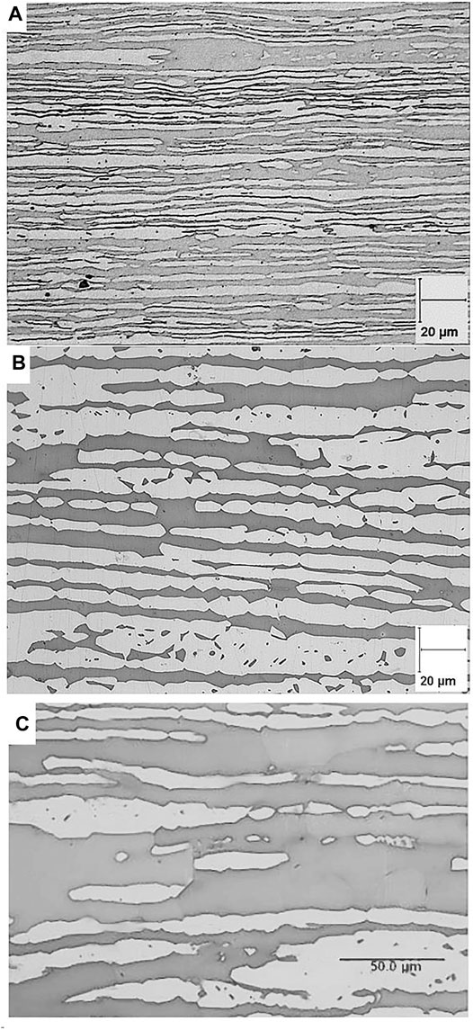
FIGURE 1. Microstructure of UNS 32750 SDSS alloys (A) thin tube SDSS 1, (B) thin plate SDSS 2, and (C) thick plate SDSS 3. Ferrite phase appears in dark gray and austenite phase in light gray.
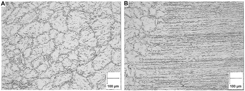
FIGURE 2. Microstructure of welded UNS 32750 SDSS 4 sample (A) weld and (B) HAZ.
The chemical compositions of the alloys were all in accordance with the specifications for UNS S32750 steel (Table 1). Their mechanical properties are indicated in Table 2. A slight decrease of the mechanical properties was observed with increasing austenite spacing, but the yield strength remained rather high compared, for instance, to forged materials (Byrne et al., 2016). It should also be pointed out that the mechanical properties were also sensitive to test temperature, with a decrease of the YS and UTS with increasing temperature.
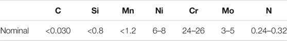
TABLE 1. Chemical composition of UNS S32750 SDSS (%) as per ASTM A240.
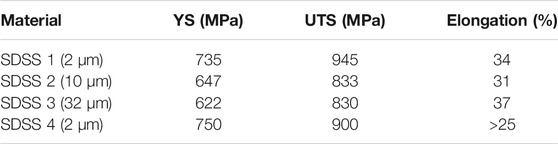
TABLE 2. Mechanical properties obtained by uniaxial tensile testing as per ASTM E8 of UNS S32750 steels at room temperature.
Specimens and Fatigue Tests
In situ fatigue tests were performed by 4-point bending. For SDSS 1 and 4, the samples were tubes with outer diameter (OD) of 25 mm and wall thickness of 2 mm. The orbital weld for SDSS4 was located at the center of the 500-mm-long specimen. For SDSS2 and 3, plates of 370 × 18 × 10 mm were sampled from the 10-mm- and 70-mm-thick plates. The load ratio (min. load over max. load) was R = 0.1, and a frequency from 0.08 to 5 Hz was used. However, most of the immersion tests were conducted at a frequency of 0.2 Hz up to 1 million cycles (approx. 58 days). No influence of the frequency was observed in this investigated range.
The tests were conducted in air and in natural seawater at room temperature (23 ± 3°C), with and without CP at −1,100 mV vs. the saturated calomel electrode (SCE). Additional tests were also conducted at 80°C ± 1°C. At least 12 samples (four load levels and three replicates) were used to plot one SN curve. In most of the cases, one additional load level was added. The open-circuit potential was monitored continuously. At the beginning of the test, the potential was stable at around −100 mV/SCE, and then, after potential ennoblement due to biofilm activity, the potential raises up to +200 mV/SCE [the potential increased within a week in agreement with results for natural seawater at room temperature (Audouard et al., 1996; Larché et al., 2010)].
A schematic representation of the equipment is given in Figure 3. The tank made of titanium was isolated from the specimen owing to ceramic cylinders. The counter electrode, in titanium mixed metal oxide (TiMMO), was positioned outside the main tank to avoid chlorination of the system. The tank was filled with natural seawater from the Bay of Brest. A circulation of seawater was imposed to renew the total volume of the tank (approx. 50 L) every day. Under such conditions, biologic activity from the natural seawater was maintained (Larche et al., 2016; Trigodet et al., 2019).
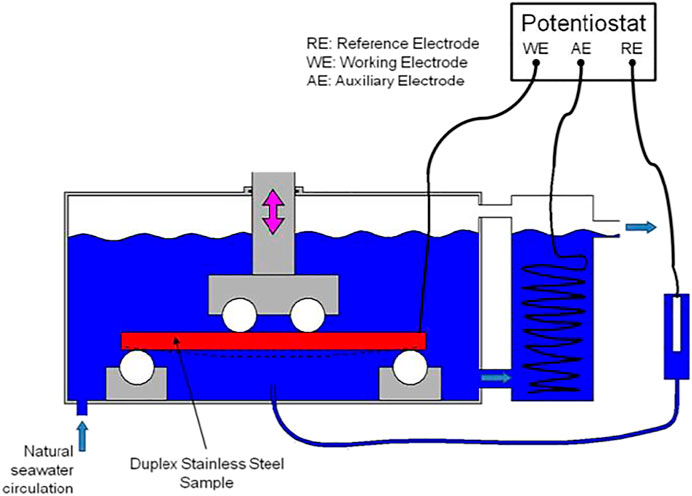
FIGURE 3. Equipment to perform the 4-point bending fatigue test in natural seawater with CP.
The specimens were tested as received, without further surface preparation at the laboratory, expect in the case of notches. These defects were prepared on plate specimens (SDSS 2) at the center along the transversal direction using wire saw and glass cutting tool to control the final shape of the notch, particularly notch tip radius in the range of 4–6 μm. The position of the notch on the samples and an example of the depth profile are shown in Figure 4. Using such a method, plastic deformation was obtained around the notch, which was representative of mechanical damages obtained on the site.
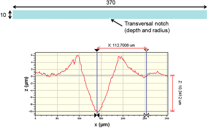
FIGURE 4. Position of the notch on the specimen and example of the profile using the glass cutting tool.
Hydrogen Quantification
Thermal desorption analysis (TDA) was performed using a katharometer (G8 Galileo from Bruker) to quantify the hydrogen content in pre-charged samples. The samples machined from tubes (approx. 2 cm long, half of the tube) were maintained under cathodic polarization at −1,100 mV/SCE for 1–30 days in natural seawater at room temperature (∼20°C) and at 80°C. Then, immediately after cathodic charging, the samples were etched using diluted nitric acid (20%) for few seconds to remove the calcareous deposit, rinsed with distilled water, and dry with blow air. Within 5 min after the end of the cathodic charging, the samples were introduced into the furnace of the hydrogen analyzer and heated up to 900°C at 1°C/s. The obtained spectra were analyzed to extract only the diffusible hydrogen content, corresponding to the amount of hydrogen in traps showing low binding energies, prone to diffuse at room temperature.
Fractography
Fracture surfaces and cross-section after fatigue testing were observed by a scanning electron microscope (SEM—SU 3500 from Hitachi). For cross-sections, the surface was prepared by mechanical grinding and polishing up to 1 μm diamond paste. The microstructure was revealed by polishing with silica colloidal suspension, without additional etching. The contrast between ferrite and austenite phases was enhanced using backscattered electrons to obtain the SEM images.
Results and Discussion
Diffusible Hydrogen Determination
Fatigue experiments were conducted in natural seawater under CP at −1,100 mV/SCE. Such conditions were known to lead to hydrogen uptake in the stainless steel as the potential was well below the water reduction potential even at the pH of natural seawater (7.9–8.0). Thus, the hydrogen uptake was quantified by TDA after pre-charging of the samples of SDSS 1 from 1 day to 30 days at 20°C and 80°C. The results are presented in Figure 5. In both cases, the hydrogen content increased with time of charging but showed a tendency to stabilize in the range of 15–30 ppm at room temperature and 35–55 ppm at 80°C.
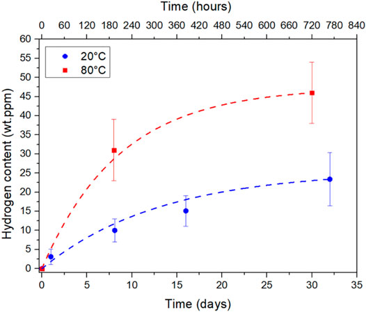
FIGURE 5. Diffusible hydrogen content in SDSS 1 after cathodic charging at room temperature and 80°C in natural seawater at −1,100 mV/SCE. The error bars indicate the standard deviation obtained using three to five samples in each case.
Fatigue Tests With and Without Cathodic Protection
The evolution of the stress amplitude as a function of the number of cycles to failure is shown in Figure 6A for specimens tested in air and at OCP. No significant difference could be noticed between the two sets of samples. Indeed, no corrosion on the SDSS was expected under the test conditions; thus, immersion in seawater did not affect fatigue performance. Failure occurs by pure mechanical loading, and fatigue mechanisms were probably the same in air and in seawater. These results were in good agreement with data from the literature obtained on similar tube samples (Chai et al., 2009b; Kivisäkk and Chai, 2009).
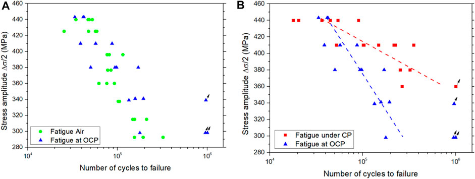
FIGURE 6. Comparison of the fatigue lives of SDSS 1 (A) in air and in natural seawater at OCP and (B) at OCP and under CP at −1,100 mV/SCE. Runouts (>1M cycles) are indicated by arrows.
The fatigue tests were also conducted under CP at a frequency of 0.2 Hz up to 1 million cycles. Such low frequency was selected to allow hydrogen uptake under the test conditions. As shown in Figure 6B, the fatigue strength under CP was higher than that in air or at the open circuit potential, particularly at lower stress amplitude, despite the expected higher amount of hydrogen (longer test time and charging). The fatigue strength was increased, despite reduction of toughness and elongation to failure which are usually observed in the presence of hydrogen for duplex stainless steels (Zheng and Hardie, 1991; El-yazgi and Hardie, 1996; San Marchi et al., 2007).
The enhancement of the fatigue life was attributed to a modification of the mechanical properties of the steel in the presence of hydrogen, as explained in the Introduction. Owing to continuous flux of hydrogen at the surface of the specimen during fatigue testing and considering that the maximum stress occurs at the outer surface of the tube, where the hydrogen concentration was at the maximum, it was expected that mechanical properties of the steel were locally improved by cathodic charging. Indeed, the yield strength of the SDSS can increase up to 15–20% at very high hydrogen content (120–130 wt. ppm) (San Marchi et al., 2007). Interestingly, the fatigue life enhancement was more pronounced at lower stress amplitude, with less accumulation of plastic strain at the surface of the specimen. Thus, hydrogen might affect the crack embryo formation in the austenite by modifying plastic strain accumulation in the austenitic grain and mobility of dislocations. At high stress amplitudes, this beneficial effect was probably compensated by the high sensitivity of the ferritic phase that cracked easily.
For large microstructures or low austenite content, the crack path is mainly observed in the sensitive ferritic phase. But, with low austenite spacing, crack will arrest at the ferrite/austenite interface, controlling the overall fatigue life of the tested sample. The crack will propagate when a critical level of damage (plastic strain) will be accumulated at the interface by the fatigue mechanism. In the presence of hydrogen, the yield strength of the austenitic steels is increased due to dynamic interactions of hydrogen with the dislocations (Robertson et al., 2009). By the localization of the plasticity (as in the HELP mechanism), strong dislocation bands will be formed in the austenite at the tip of the crack (Abraham and Altstetter, 1995). Thus, this mechanism could limit the accumulation of fatigue damage, making a favorable reversible path for the movement of the dislocations during alternated tension/compression loads.
Influence of the Test Temperature
The fatigue tests were also conducted under CP at 80°C on SDSS 1. To enhance the interaction of hydrogen with the microstructure, a pre-charging of 8 days under CP at 80°C was systematically applied on the specimens prior to fatigue loading. In this case, initial hydrogen content around 30 ppm could be expected in the samples as detailed previously in Figure 5.
As shown in Figure 7A, the fatigue life seemed to decrease at 80°C compared to tests performed at 20°C. However, considering the drop of mechanical strength with the temperature, with yield strength of 743 MPa at 20°C and 678 MPa at 80°C, the strength amplitude was normalized to compare the data obtained at these two temperatures. Owing to such normalizing, the fatigue curves were finally rather similar as shown in Figure 7B. Thus, even under severe hydrogen charging conditions, the fatigue performance of the SDSS 1 was not affected by cathodic charging.
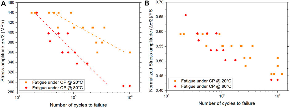
FIGURE 7. (A) SN curves obtained at 20°C and 80°C and (B) normalized by the YS of the SDSS 1 at the tested temperatures.
Influence of Austenite Spacing
The previous results highlighted the absence of deleterious effect of CP on the fatigue performance of SDSS 1 with very small austenite spacing. The same fatigue tests were conducted on SDSS 2 and 3, with larger austenite spacing of 10 and 32 μm, respectively. In terms of fatigue resistance, as shown in Figure 8A, SDSS 3 with larger austenite spacing showed the lowest performance. However, to compare the alloy, the stress amplitude was normalized by the YS. In this case, as illustrated in Figure 8B, the performance of SDSS 1 and 2 was rather similar, whereas the fatigue resistance of SDSS 3 was clearly lower. Thus, the beneficial effect of hydrogen on the mechanical resistance of the alloy was compensated by some embrittlement mechanism under fatigue loading.
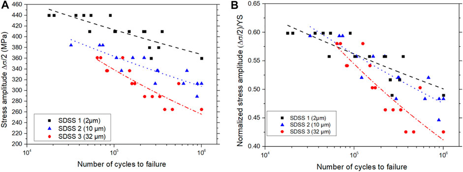
FIGURE 8. (A) SN curves obtained for SDSS 1, 2, and 3 and (B) normalized by the YS of each alloy.
The fracture aspect of the SDSS 3 sample after fatigue testing under CP is presented in Figure 9A. Some brittle areas were clearly observed on the fracture surfaces, corresponding to the ferritic phase. This highlighted the higher sensitivity of ferrite to hydrogen embrittlement, whereas the austenitic phase remained ductile. On cross-sections (Figure 9B), secondary cracks were systematically found in the ferritic phase. The cracking was facilitated owing to the high austenite spacing. As a result, the stress intensity factor at the ferrite/austenite interface was necessarily higher for SDSS 3 than for the other two stainless steels. The crack propagation into the austenitic phase was finally facilitated, which was the critical step controlling the overall fatigue performance. However, it should be pointed out that fatigue resistance under CP was still higher than for specimens tested in air, meaning that the beneficial effect from hydrogen uptake was not totally erased.
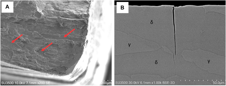
FIGURE 9. (A) Fracture aspect of the SDSS 3 sample after fatigue testing under CP and (B) example of secondary crack in the ferritic phase (δ) observed on the cross-section. Cleavage-like failure in the ferritic phase is indicated by arrows.
Influence of Stress Concentration
For real structures, stress concentrations linked to the design of the components or due to some damages (impact, tool scratching, and so on) cannot be avoided. Thus, fatigue tests were performed in seawater with and without CP on samples with a controlled notch showing a depth in the range of 10–250 μm. This way, the hydrogen effects at the notch root, with important cyclic plastic deformation, were expected to decrease the fatigue life of the specimens.
As shown in Figure 10, a critical notch depth around 90–100 μm was necessary to decrease the fatigue life of the specimens. Indeed, with a notch depth of 50 μm and even 88 μm, the failures were observed out of the notch, showing that stress concentration did not impact the fatigue performance of the specimens tested under CP. With a notch depth over 90 μm, the fatigue life reduction compared to un-notched samples increased with notch depth. However, under CP, at equivalent notch depth, the fatigue performance was still better than at OCP, which highlighted again the beneficial effect from hydrogen uptake, even in the case of rather large cyclic plastic straining.
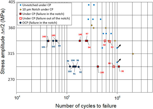
FIGURE 10. Impact of notch depth on the fatigue life of SDSS 2 samples tested in seawater at OCP and under CP. The notch depth in micrometer is indicated for each sample (in blue for OCP and red for CP).
During fatigue tests under CP, crack initiation occurs at several locations, mainly in the ferritic phase, but the crack growth mechanism is controlled by crack propagation from the ferritic phase to the austenitic one. To initiate a crack at the notch root, the stress concentration should be, at least, as important as for cracks formed at the surface of the sample out of the notch. However, from the fabrication process of the notch, using a specific glass cutting tool, local hardening and compressive stresses could be expected, which might decrease the local sensitivity of the microstructure to fatigue crack initiation. Finally, the stress concentration factor Kt for fatigue crack initiation at the notch root can be estimated using Eq. 1:
with
Influence of Welding
Specimens made in SDSS 4 were tested under CP and at OCP in natural seawater. Two configurations were tested, tube specimens without and with an orbital weld. In the case of non-welded specimens, the results were rather similar to the data obtained previously with SDSS 1. As shown in Figure 11A, the fatigue performance was, indeed, enhanced under CP compared to OCP condition.
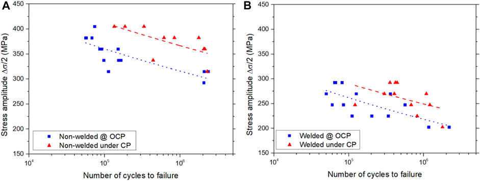
FIGURE 11. SN curves obtained under CP and at OCP on (A) non-welded specimens and (B) specimens with an orbital weld.
For welded specimens, as presented in Figure 11B, the fatigue performance was decreased compared to samples tested without the orbital weld. However, the fatigue life of welded specimens under CP was still slightly higher than that at OCP. The failure occurred systematically at the weld toe due to both microstructural modifications and stress concentration (non-machined weld). Thus, the beneficial effect from hydrogen uptake was still efficient even in the HAZ/weld area, with very different austenite and ferrite distribution.
As shown in Figure 12A, a fully ductile failure was obtained for the non-welded specimens tested at OCP. On the fracture surfaces, presented in Figures 12B,D, brittle areas (cleavage-like) were systematically observed for specimens tested under CP, both non-welded and welded ones. However, due to difference of the microstructure at the crack location, the brittle areas were larger and more equiaxed for welded samples, corresponding to the microstructure at the weld/HAZ interface. These features matched with the ferritic grains shown previously in Figure 2.
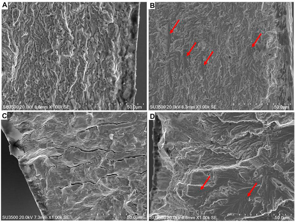
FIGURE 12. SEM observations of the fracture surfaces after fatigue testing in seawater at (A,C) OCP and (B,D) under CP for (A,B) non-welded samples and (C,D) samples with an orbital weld. Brittle areas are indicated by red arrows.
For the welded specimens tested at OCP, some secondary cracks were systematically observed on the fracture surface, which were not close to the crack initiation site shown in Figure 12C. These features highlighted higher sensitivity to cracking of the weld/HAZ area.
Conclusion
The fatigue performance of UNS S32750 stainless steel was evaluated in air and in natural seawater with and without cathodic protection (CP). Selected conditions of CP (−1,100 mV/SCE) generated diffusible hydrogen into the test samples which was able to interact with the microstructure. The selected alloys and welding procedure, according to the most recent state of the art, lead to good microstructure (no deleterious secondary phases) and optimal ferrite/austenite balance. Alloys presented systematically rather fine structures, more representative of wrought alloys. Thus, the results should not be extrapolated to larger structures, for example, forgings, showing specific cracking paths, secondary phases, austenite distribution, and mechanical properties. From the results, the following conclusions could be drawn:
• The fatigue performance at OCP in seawater and in air was similar as no risk of pitting was expected for this alloy under the tested conditions.
• Under CP, an increase of fatigue life was systematically observed for low and high austenite spacing at room temperature and at 80°C. The improvement was more pronounced at lower stress amplitude.
• Increasing the local stress and plastic strain with a notch affected the overall fatigue performance, but hydrogen uptake was still beneficial compared to OCP condition.
• The presence of an orbital weld, due to both microstructural evolutions and stress concentration at the weld toe, decreased the fatigue resistance of the tested specimens, but CP was still beneficial compared to OCP condition.
• Brittle aspects and cracking were systematically observed in the ferritic phase, linked to higher sensitivity of ferrite to hydrogen embrittlement.
For the SDSS, the ferritic phase is particularly sensitive to hydrogen embrittlement and can show brittle aspects when tested in natural seawater under normal operating conditions of the CP system. Despite these features, the fatigue performance of the samples tested under CP remained systematically, at least, equal to the performance at OCP or in air, but in most of the cases, fatigue life enhancement is observed. The quantity of hydrogen introduced into the SDSS samples under tested CP conditions led to an overall increase of the mechanical properties of the alloy, keeping the deleterious effect of hydrogen on the ferritic phase negligible in the range of investigated austenite spacing. Such behavior could be linked to the localization of the plasticity in the austenite phase in the presence of hydrogen, forming a favorable path for dislocation mobility. This would delay damage accumulation by the fatigue mechanism in the austenite phase and, thus, enhance the fatigue life.
Thus, the SDSS material prepared according to the state of the art showing a rather fine structure (wrought alloys) and good austenite/ferrite balance shows relative immunity to HE, even under fatigue conditions, in natural seawater under normal operating conditions of the CP system (−1,100 mV/SCE).
To extend this research for alloys showing coarser microstructure, additional experiments should be performed according to the same test procedure. At the end, the results may provide the basis for revision of knockdown factors applied to the design of subsea equipment.
Data Availability Statement
The original contributions presented in the study are included in the article/Supplementary Material; further inquiries can be directed to the corresponding author.
Author Contributions
FV, DT, and NL contributed to the conception and design of the study. FV and GR performed the experimental work and analyzed the data. FV wrote the original and revised manuscript. All authors contributed to manuscript revision and read and approved the submitted version.
Funding
The authors declare that this study received funding from ARCOR association in the frame of the Member Research Consortium (MRC) “Marine Corrosion”. The industrial members of this association are: Aker Solutions, Aperam, DGA, EDF, Equinor, FlexiFrance/TechnipFMC, Industeel ArcelorMittal, IxBlue, Neotiss, National Oilwell Varco, Outokumpu, Saipem, Sandvik, Thalès, TotalEnergies, Vallourec, Veolia, voestalpine BOHLER Edelstahl, and Volvo Penta. The design of the study and the decision to publish the paper was discussed and validated with the consortium. The funders were not involved in the collection, analysis, interpretation of data and the writing of this article.
Conflict of Interest
The authors declare that the research was conducted in the absence of any commercial or financial relationships that could be construed as a potential conflict of interest.
Publisher’s Note
All claims expressed in this article are solely those of the authors and do not necessarily represent those of their affiliated organizations, or those of the publisher, the editors, and the reviewers. Any product that may be evaluated in this article, or claim that may be made by its manufacturer, is not guaranteed or endorsed by the publisher.
Acknowledgments
The authors acknowledge the industrial partners of the Member Research Consortium (MRC) “Marine Corrosion” from the ARCOR association for funding, material supply, and fruitful discussions on the experimental protocol and results: Aker Solutions, Aperam, DGA, EDF, Equinor, FlexiFrance/TechnipFMC, Industeel ArcelorMittal, IxBlue, Neotiss, National Oilwell Varco, Outokumpu, Saipem, Sandvik, Thalès, TotalEnergies, Vallourec, Veolia, voestalpine BOHLER Edelstahl, and Volvo Penta.
References
A Hosseini, V., Hurtig, K., Eyzop, D., Östberg, A., Janiak, P., and Karlsson, L. (2019). Ferrite Content Measurement in Super Duplex Stainless Steel Welds. Weld. World 63, 551–563. doi:10.1007/s40194-018-00681-1
Abraham, D. P., and Altstetter, C. J. (1995). Hydrogen-enhanced Localization of Plasticity in an Austenitic Stainless Steel. Mmta 26, 2859–2871. doi:10.1007/bf02669644
Alvarez-Armas, I., Krupp, U., Balbi, M., Hereñú, S., Marinelli, M. C., and Knobbe, H. (2012). Growth of Short Cracks during Low and High Cycle Fatigue in a Duplex Stainless Steel. Int. J. Fatigue 41, 95–100. doi:10.1016/j.ijfatigue.2012.01.010
Antolovich, S. D., and Armstrong, R. W. (2014). Plastic Strain Localization in Metals: Origins and Consequences. Prog. Mater. Sci. 59, 1–160. doi:10.1016/j.pmatsci.2013.06.001
API Technical (2011).Use of Duplex Stainless Steels in Oil and Refining Industry. API Technical Report 938-C.
Arabi, S. H., Pouranvari, M., and Movahedi, M. (2019). Pathways to Improve the Austenite-Ferrite Phase Balance during Resistance Spot Welding of Duplex Stainless Steels. Sci. Technol. Welding Joining 24, 8–15. doi:10.1080/13621718.2018.1468949
Audouard, J.-P., Thierry, D., Feron, D., Compere, C., Scotto, V., Wallen, B., et al. (1996). Crevice Corrosion Resistance of Stainless Steels in Natural Sea Water. Results of a Paneuropean Test Programme. Düsseldorf, Germany: Conference Stainless Steels, 83–88.
Beachem, C. D. (1972). A New Model for Hydrogen-Assisted Cracking (Hydrogen "embrittlement"). Mt 3, 441–455. doi:10.1007/bf02642048
Birnbaum, H. K., and Sofronis, P. (1994). Hydrogen-enhanced Localized Plasticity-A Mechanism for Hydrogen-Related Fracture. Mater. Sci. Eng. A 176, 191–202. doi:10.1016/0921-5093(94)90975-x
Brass, A.-M., and Chêne, J. (2006). Hydrogen Uptake in 316L Stainless Steel: Consequences on the Tensile Properties. Corrosion Sci. 48, 3222–3242. doi:10.1016/j.corsci.2005.11.004
Byrne, G., Francis, R., and Warburton, G. (2016). “Hydrogen Induced Stress Cracking (HISC) Resistance and Improvement Methods for Super Duplex Stainless Steels,” in NACE Corros, Vancouver, BC, Canada, March 2016, (CORROSION 2016)
Cassagne, T., and Busschaert, F. (2005). “A Review on Hydrogen Embrittlement of Duplex Stainless Steels,” in NACE Int. Corros. Conf., Houston, TX, April 2005 (CORROSION 2005), 1–26.
Chai, G. (2006). Fatigue Behaviour of Duplex Stainless Steels in the Very High Cycle Regime. Int. J. Fatigue 28, 1611–1617. doi:10.1016/j.ijfatigue.2005.06.054
Chai, G., Kivisäkk, U., Tokaruk, J., and Eidhagen, J. (2009). “Hyper Duplex Stainless Steel for Deep Subsea Applications,” in Stainl (Maastricht, Netherlands: Stainless Steel World Conference and Exhibition).
Chai, G., Lillbacka, R., and Peng, R. (2011). “Advances in Heterogeneous Material Mechanics (ICHMM-2011),” in Proceedings of the Third International Conference on Heterogeneous Material Mechanics, Shanghai, China, May 22-26, 2011.
Chai, G., Ronneteg, S., Kivisäkk, U., Peng, R. L., and Johansson, S. (2009). Mechanisms of Hydrogen Induced Stress Crack Initiation and Propagation in Super Duplex Stainless Steels. Steel Res. Intenational. 80, 482–487.
Delafosse, D., and Magnin, T. (2001). Hydrogen Induced Plasticity in Stress Corrosion Cracking of Engineering Systems. Eng. Fracture Mech. 68, 693–729. doi:10.1016/s0013-7944(00)00121-1
Dönges, B., Giertler, a., Krupp, U., Fritzen, C.-P., and Christ, H.-J. (2014). Significance of Crystallographic Misorientation at Phase Boundaries for Fatigue Crack Initiation in a Duplex Stainless Steel during High and Very High Cycle Fatigue Loading. Mater. Sci. Eng. A. 589, 146–152.
El-yazgi, A. A., and Hardie, D. (1996). The Embrittlement of a Duplex Stainless Steel by Hydrogen in a Variety of Environments. Corrosion Sci. 38, 735–744. doi:10.1016/0010-938x(95)00162-d
Francis, R., Byrne, G., and Warburton, G. R. (1997). Effects of Cathodic protection on Duplex Stainless Steels in Seawater. Corrosion 53, 234–240. doi:10.5006/1.3280465
Gaspard, V. (2014). Interactions Hydrogène-Plasticité dans les Alliages Ferritiques. PhD Thesis France: Saint-Etienne.
Girardin, G. (2004). Interactions hydrogène plasticité dans le nickel et ses alliages. PhD Thesis France: Saint-Etienne.
Gupta, A., Kumar, A., Baskaran, T., Arya, S. B., and Khatirkar, R. K. (2018). Effect of Heat Input on Microstructure and Corrosion Behavior of Duplex Stainless Steel Shielded Metal Arc Welds. Trans. Indian Inst. Met. 71, 1595–1606. doi:10.1007/s12666-018-1294-z
Kivisäkk, U., and Chai, G. (2009). Corrosion Fatigue Properties of Sandvik SAF 3207 HD Umbilical Tubes. Nice, France: Conference Eurocorr.
Konosu, S., and Nakaniwa, T. (1998). Hydrogen Cracking of Ferritic Stainless Steel thermal Storage Tanks. Eng. Fail. Anal., 212–220. doi:10.1016/s1350-6307(98)00020-x
Larche, N., Thierry, D., Boillot, P., Cassagne, T., Blanc, J., Dezerville, P., et al. (2016). “Crevice Corrosion Performance of High Grade Stainless Steels and Ni-Based Alloys in Natural and Treated Seawater,” in NACE - Int. Corros. Conf. Ser. Vancouver, BC, Canada, March 2016, (CORROSION 2016), 779–792.
Larché, N., Thierry, D., Debout, V., Blanc, J., Cassagne, T., Peultier, J., et al. (2010). “Crevice Corrosion of Duplex Stainless Steels in Natural and Chlorinated Seawater,” in Duplex World (France: Beaune).
Liang, X. Z., Zhao, G.-H., Dodge, M. F., Lee, T. L., Dong, H. B., and Rivera-Díaz-del-Castillo, P. E. J. (2020). Hydrogen Embrittlement in Super Duplex Stainless Steels. Materialia 9, 100524. doi:10.1016/j.mtla.2019.100524
Lillbacka, R., Chai, G., Ekh, M., Liu, P., Johnson, E., and Runesson, K. (2007). Cyclic Stress-Strain Behavior and Load Sharing in Duplex Stainless Steels: Aspects of Modeling and Experiments. Acta Materialia 55, 5359–5368. doi:10.1016/j.actamat.2007.05.056
Lynch, S. P. (1988). Environmentally Assisted Cracking: Overview of Evidence for an Adsorption-Induced Localised-Slip Process. Acta Metallurgica 36, 2639–2661. doi:10.1016/0001-6160(88)90113-7
Magnin, T., Bosch, C., Wolski, K., and Delafosse, D. (2001). Cyclic Plastic Deformation Behaviour of Ni Single Crystals Oriented for Single Slip as a Function of Hydrogen Content. Mater. Sci. Eng. A 314, 7–11. doi:10.1016/s0921-5093(00)01920-1
Michler, T., and Naumann, J. (2010). Microstructural Aspects upon Hydrogen Environment Embrittlement of Various Bcc Steels. Int. J. Hydrogen Energ. 35, 821–832. doi:10.1016/j.ijhydene.2009.10.092
NACE (2015). NACE MR0175, ISO 15156, NACE/ISO, Petroleum and Natural Gas Industries - Materials for Use in H2S Containing Environments in Oil and Gas Production.
Oltra, R., Bouillot, C., and Magnin, T. (1996). Localized Hydrogen Cracking in the Austenitic Phase of a Duplex Stainless Steel. Scripta Materialia 35, 1101–1105. doi:10.1016/1359-6462(96)00293-x
Örnek, C., Reccagni, P., Kivisäkk, U., Bettini, E., Engelberg, D. L., and Pan, J. (2018). Hydrogen Embrittlement of Super Duplex Stainless Steel – towards Understanding the Effects of Microstructure and Strain. Int. J. Hydrogen Energ. 43, 12543–12555.
Örnek, C., Larsson, A., Harlow, G. S., Zhang, F., Kroll, R., Carlà, F., et al. (2020). Metastable Precursor Structures in Hydrogen-Infused Super Duplex Stainless Steel Microstructure – an Operando Diffraction experiment. Corros. Sci. 176, 109021.
Örnek, C., Şeşen, B. M., and Ürgen, M. K. (2021). Understanding Hydrogen-Induced Strain Localization in Super Duplex Stainless Steel Using Digital Image Correlation Technique. Met. Mater. Int.
Ozlati, A., and Movahedi, M. (2020). Effect of In Situ Post Weld Heat Treatment on Mechanical Behavior and Austenite–Ferrite Phase Balance of Fe-Cr-Ni/Fe-Cr Stainless Steels Upset Resistance Dissimilar Weld. J. Manuf. Sci. Eng. 142. doi:10.1115/1.4045656
Putz, A., Hosseini, V. A., Westin, E. M., and Enzinger, N. (2020). Microstructure Investigation of Duplex Stainless Steel Welds Using Arc Heat Treatment Technique. Weld. World 64, 1135–1147. doi:10.1007/s40194-020-00906-2
Ranganathan, N., Aldroe, H., Lacroix, F., Chalon, F., Leroy, R., and Tougui, A. (2011). Fatigue Crack Initiation at a Notch. Int. J. Fatigue 33, 492–499. doi:10.1016/j.ijfatigue.2010.09.007
Robertson, I. M., Birnbaum, H. K., and Sofronis, P. (2009). “Chapter 91 Hydrogen Effects on Plasticity,” in Dislocations in Solids. Editors J. P. Hirth, and L. Kubin 15, 249–293. doi:10.1016/s1572-4859(09)01504-6
San Marchi, C., Somerday, B. P., Zelinski, J., Tang, X., and Schiroky, G. H. (2007). Mechanical Properties of Super Duplex Stainless Steel 2507 after Gas Phase Thermal Precharging with Hydrogen. Metall. Mat Trans. A. 38, 2763–2775. doi:10.1007/s11661-007-9286-3
Świerczyńska, A., Fydrych, D., Landowski, M., Rogalski, G., and Łabanowski, J. (2020). Hydrogen Embrittlement of X2CrNiMoCuN25-6-3 Super Duplex Stainless Steel Welded Joints under Cathodic protection. Constr. Build. Mater. 238, 117697.
Świerczyńska, A., Łabanowski, J., Michalska, J., and Fydrych, D. (2017). Corrosion Behavior of Hydrogen Charged Super Duplex Stainless Steel Welded Joints. Mater. Corros. 68, 1037–1045.
Trigodet, F., Larché, N., Morrison, H. G., Jebbar, M., Thierry, D., and Maignien, L. (2019). Electroactive Bacteria Associated with Stainless Steel Ennoblement in Seawater. Front. Microbiol. 10, 170. doi:10.3389/fmicb.2019.00170
Turnbull, A., and Hutchings, R. B. (1994). Analysis of Hydrogen Atom Transport in a Two-phase alloy. Mater. Sci. Eng. A 177, 161–171. doi:10.1016/0921-5093(94)90488-x
Keywords: super duplex stainless steel, hydrogen, natural seawater, fatigue, cathodic protection (CP)
Citation: Vucko F, Ringot G, Thierry D and Larché N (2022) Fatigue Behavior of Super Duplex Stainless Steel Exposed in Natural Seawater Under Cathodic Protection. Front. Mater. 9:826189. doi: 10.3389/fmats.2022.826189
Received: 30 November 2021; Accepted: 11 January 2022;
Published: 31 January 2022.
Edited by:
Cem Örnek, Istanbul Technical University, TurkeyReviewed by:
Dariusz Fydrych, Gdansk University of Technology, PolandMustafa Ürgen, Istanbul Technical University, Turkey
Copyright © 2022 Vucko, Ringot, Thierry and Larché. This is an open-access article distributed under the terms of the Creative Commons Attribution License (CC BY). The use, distribution or reproduction in other forums is permitted, provided the original author(s) and the copyright owner(s) are credited and that the original publication in this journal is cited, in accordance with accepted academic practice. No use, distribution or reproduction is permitted which does not comply with these terms.
*Correspondence: Flavien Vucko, flavien.vucko@institut-corrosion.fr