Broadband Sound Absorption of Subwavelength Porous Meta-Liner
 Heye Xiao
 Tianyue Yuan2†
  Jie Zhou
- 1Unmanned System Research Institute, Northwestern Polytechnical University, Xi’an, China
- 2School of Aeronautics, Northwestern Polytechnical University, Xi’an, China
- 3First Aircraft Design and Research Institute, Aviation Industry Corporation of China Ltd., Xi’an, China
This work proposes a subwavelength porous meta-liner with broadband sound absorption from 900 to 1,200 Hz. The meta-liner consists of four subunits, which are made up of porous material and hollow coiling slit embedded in it. Each subunit is designed by adjusting the length of its coiling slit to achieve resonance in the target frequency and examined by the finite element method (FEM). These subunits are arranged in an axial direction uniformly and radial direction periodically to propose a meta-liner duct. Then, the noise reduction of the propeller system with the meta-liner duct is measured by the microphone array. The result shows that the propeller with the meta-liner duct can reduce the noise level of the ducted propeller between 3.6 and 5.5 dB in the design frequency range, which also effectively reduces the noise level in the broadband frequency range. Therefore, the meta-liner shows a good application prospect in the noise reduction of the propeller.
Introduction
The noise reduction problem of small-scale unmanned aerial vehicles (UAVs) is widely researched for the improvement of the competitiveness in the civil market and the increase of the concealment in the military application (Mueller, 2001; Christian and Cabell, 2017). The primary noise source of the UAVs is the propeller noise (Zhou and Fattah, 2017). The propeller emission noise may be divided into broadband noise and tonal noise (Kemp, 1932; Kurtz and Marte, 1970). The broadband noise results from the turbulence generated by the interaction between the air and the propeller blade, and the tonal noise comes from the motion of the rotor.
Usually, the tonal noise is a significant noise source, which is most prominent at the harmonics of the passing frequency of the propeller blade. In order to control the noise of the propeller, several techniques have been utilized to reduce the noise level both in the generation and propagation of the noise. For example, the serrated trailing edge blades can reduce the broadband noise and the ducted propeller. Except for reducing the noise level of the propeller, the ducted propeller can also improve the aerodynamic efficiency of the UAVs and protect the propeller blade from damage.
Meanwhile, Pereira et al. pointed out that a hard wall duct can result in a slight increment of noise if the duct is not designed well (Pereira, 2008). Malgoezar et al. investigated the characteristics of the noise of the propeller with a rigid duct according to the experiment (Malgoezar et al., 2019). They found the introduction of the duct will result in the increase of the broadband noise, a decrease of the first harmonics, and an overall decrease in the noise level. Furthermore, Lu et al. investigated the acoustic performance of the rigid duct and a micro-perforated duct. Their acoustic benefits were not as high as expected (Lu et al., 2016). Guo et al. designed a lined duct using a Helmholtz resonator with an extended neck and achieved approximately 3 dB noise reduction in the range of 700–1,000 Hz (Guo et al., 2021). In general, a ducted propeller can significantly increase the aerodynamic and acoustic performance if the duct is designed properly. There is still a lack of design for the new ducted propellers to reduce the propeller noise in the wider frequency. Moreover, it is significant to control the weight of the ducted propellers to meet the lightweight requirement of the aircraft (Reducing the weight of ai, 2014). Therefore, a new lightweight duct occupying a small space, which also has excellent acoustic performance both in low and high frequencies, needs to be studied and designed.
Traditional Helmholtz resonator (HR)-type acoustic liners, composed of a honeycomb layer placed between a perforated plate and a rigid back-plate (Nark and Jones, 2017), are commonly used to control noise in many duct sound suppression problems (e.g., aero-engines and air-conditioning ducts). This type of liner is effective across a narrow band of frequencies (Durau, 2012), thus making it unsuitable for broadband noise reduction. Fortunately, new acoustic metamaterials offer greater potential for noise control. Most metamaterials for sound absorption have only been studied in lab tests (Li and Assouar, 2016; Zhou et al., 2017; Fang et al., 2018a; Fang et al., 2018b; Wang et al., 2018; Wang et al., 2019; Wu et al., 2019; Li et al., 2020; Liu et al., 2020; Zhao et al., 2020; Liang et al., 2021; Liu et al., 2021), leaving a research gap of their applications to aeroacoustic problems. In this article, we present the numerical and experimental investigations on sound absorption of subwavelength porous meta-liner. The coiling slit with rigid walls is embedded in the porous material to build the subunit of the meta-liner. The sound absorption of each subunit in the meta-liner is examined by using the finite element method (FEM). Then, the designed meta-liner, which is composed of several subunits, is applied in the duct. A meta-liner duct is proposed to reduce the propeller-induced noise. Finally, we verify the noise reduction of the designed meta-liner in the duct for the propeller system by carrying out experiments.
Meta-Liner Subunit Description and Design
Meta-Liner Subunit Description
The propeller-induced noise includes broadband noise and tonal noise. Usually, the porous material panel and microperforated panel are used to reduce broadband noise at high frequency and tonal noise at low frequency, respectively. It is perfect to integrate these two structures in the limited space for reducing the propeller-induced noise in the wide frequency range. Therefore, the subunit of a meta-liner is designed and shown in Figure 1. It is seen that the subunit is composed of a coiling slit and porous material. The coiling slit with rigid walls is embedded in porous material to build the subunit and works as a composite structure.

FIGURE 1. Structure of acoustic liner and its subunit.
Melamine foam is chosen as the base porous material of the subunit in the design, because of its good sound absorption performance in the high-frequency range. A microperforated panel is placed at the entrance of the coiling slit, which constitutes a microperforated panel (MPP) system. The length of the sound propagating channel in the coiling slit is longer and presents a good sound absorption performance at low frequency. The subunit structure and its cross section are also shown in Figure 1. The length, width, and height of the whole subunit are l, b, and h, respectively. The width and height of the porous material part are bp and hp, respectively. The thickness of the rigid wall is hw, and the diameter of the micro-perforation is r. The width of the acoustic channel in the coiling slit is ba. To obtain the broadband sound absorption at target frequencies, it is significant to design the parameters of the subunit and construct a meta-liner.
Calculation of Absorption Performance by the Finite Element Method
As a powerful calculation method, the FEM is widely used in the sound absorption performance prediction of acoustic metamaterials. Therefore, the sound absorption performance of the designed meta-liner is calculated by the FEM in this study. The acoustic control equation considering non-viscosity and thermal loss is also built first in the FEM, which can be expressed as
where c0 is the speed of sound, p is the acoustic pressure, and
where
Under the combined effect of viscous loss and heat conduction absorption, the density change of the acoustic medium can be expressed as
where βT is the isothermal compressibility.
There are hard boundary conditions around the structure, and the total temperature change Tt and boundary velocity ut on the boundary are zero:
If the boundary condition belongs to a soft type of the porous material, the density and bulk modulus should be obtained to the present boundary velocity. The vibration of the skeleton in the porous material has a very small effect on acoustic performance and can be ignored. Assuming that the skeleton is rigid, the sound propagation in the porous material can be described by the Johnson–Champoux–Allard model (JCA model), which can describe the acoustic properties of porous materials accurately. In this study, the equivalent density of porous material ρe based on the JCA model can be written as (Allard and Atalla, 2009)
The equivalent bulk modulus Ke is written as
where
The boundary conditions are substituted into Eq. 2–4 with the sound pressure of the incident field, and the sound pressure of the reflected field can be calculated. The reflection coefficient of the composite structure can be expressed as
where Pr and Pi are the average sound pressure of the incident field and the average reflected field, respectively. The sound absorption of the metasurface can then be obtained by
In this article, a finite element solver COMSOL Multiphysics is implemented to solve the problem of sound absorption performance mentioned above. The thermoviscous acoustics module is used to study the sound pressure distribution of the small holes, considering the effect of thermal viscosity on sound waves.
The acoustic property of the porous material is described by the JCA model. In the JCA model, the five parameters of the melamine foam used in this study are
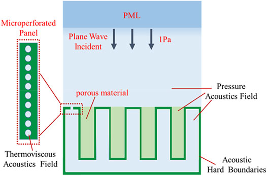
FIGURE 2. Structure of acoustic liner and its subunit.
Meta-Liner Subunit Design
The target frequency range of the meta-liner is chosen as 900–1,200 Hz in this study. To obtain broadband absorption performance, several subunits with different parameters are designed for achieving good absorption performance at different frequencies and combined to work for reducing noise in broadband frequency. The target frequency of sound absorption is tunable by changing the length of the coiling slit. The expected length of the coiling slit can be adjusted by placing a rigid partition into the slit, while the thickness and width of the whole structure are unchanged. Therefore, the whole size of the subunit is designed as 50 mm (length l) × 50 mm (width b) × 10 mm (height h), and the thicknesses hw of the rigid wall of the subunit and the diameter r of the micro-perforation are both 1 mm. The sound absorption peaks of these structures are chosen as 910 Hz, 1,000 Hz, 1,110 Hz, and 1,140 Hz. For the convenience of description, these subunits are numbered sequentially 1, 2, 3, and 4, as shown in Figure 3. The width ba of the cavity is designed as 2 mm. By the finite element method, the absorption performances of these subunits are calculated and plotted in Figure 3. The highest sound absorption coefficients of these subunits are all above 0.9. Therefore, broadband sound absorption can be well achieved by combining these four subunits into a meta-liner.
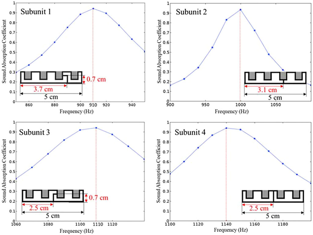
FIGURE 3. Sound absorption coefficient of each subunit.
Experiment Validation of Meta-Liner
Application of Meta-Liner in the Duct
The duct is a cylinder-shaped structure and is shown in Figure 4. Its length, diameter, and thickness are L, D, and t, respectively. In this article, the length L of the duct is selected as 150 mm. The diameter D and the thickness t of the duct are chosen as 254 and 12 mm, respectively. To decrease the propeller-induced noise, subunit 1 to subunit 4 of the meta-liner are arranged uniformly from S1 to S4 along the length direction inside the duct. Also, these subunits are arranged periodically along the circumferential direction of the duct. Then, the meta-liner duct is proposed and made by 3D printing.
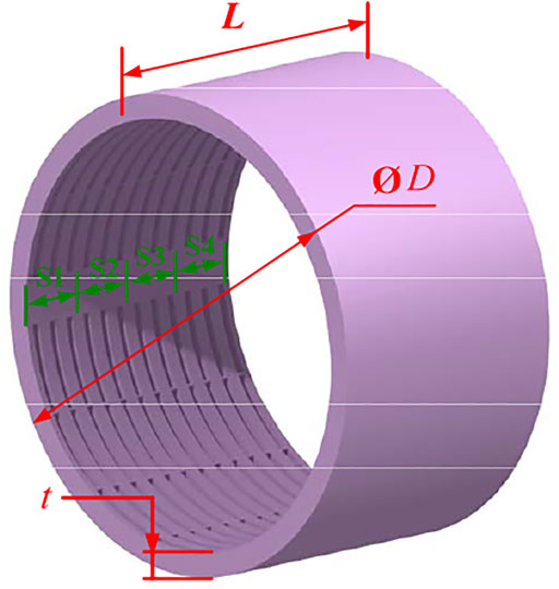
FIGURE 4. Structure of the meta-liner duct.
Experimental Configurations
In this work, a commercial fixed-wing propeller was used for testing. As shown in Figure 5A, the propeller is made of glass fiber nylon with an outer diameter of 228.6 mm (9 inches), and its weight is 17.4 g. The distance between the propeller tip and the internal face of the duct is 2.7 mm. The propeller is driven by a brushless motor (X2814-KV1, 200). The speed of the motor is controlled by the control transceiver system WFT07. Figures 5B,C present the brushless motor and WFT70, respectively. The entire blade rotation system is fixed on the optical vibration isolation table to avoid test errors caused by the shaking of the propeller.
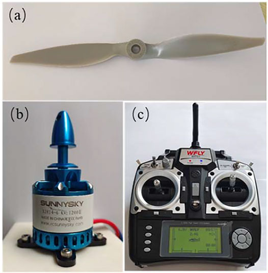
FIGURE 5. Photographs of the (A) propeller, (B) motor, and (C) remote-controller.
The experimental study focuses on the overall noise of the propeller system that varied with the change of the meta-liner duct. A ring microphone array was used to measure the effect of the meta-liner on the propeller noise. It was placed at a distance of 1.47 m from the propeller blades for testing. In order to reduce interference from the flow field, each microphone was covered with a spherical windscreen, as shown in Figure 6A. The microphone array is composed of 40 GRAS 40PH free-field array microphones. The minimum inner ring diameter and the maximum outer ring diameter of the array were set as 0.2 and 0.8 m, respectively, which are shown in Figure 6B. The center of the microphone array was aligned with the center of the propeller. The sound signal was acquired by the NI PXIe-4499 system. The sampling frequency for the acoustic test was selected as 20,000 Hz. The experiment was carried out in the anechoic room (size 2 m × 2.8 m × 2.5 m, cutoff frequency 275 Hz) of Northwestern Polytechnical University. The established system for noise reduction measurement of the meta-liner duct is shown in Figure 7.
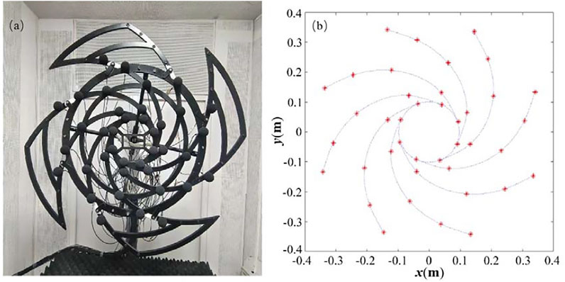
FIGURE 6. (A) Photograph of the microphone array and (B) sketch of microphone position.
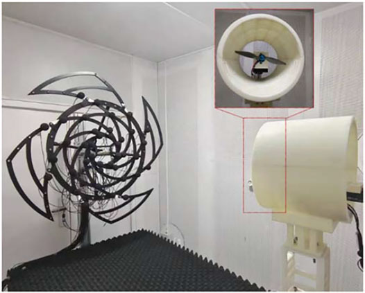
FIGURE 7. Test system arranged in the anechoic chamber.
Experimental Results and Discussions
In order to compare the sound suppression performance of the rigid duct and the meta-liner duct, the average spectrum level is used to evaluate the general noise level. According to the data obtained by the microphone array, it can be expressed by
where j is the index of the microphones, n is the number of the microphones,
which can be viewed as the overall sound pressure level (OASPL). The factor
During the test, the motor was kept at the same speed of 5,100 r/min. The center of the duct and the center of the propeller blade were kept concentric, and the distance between the center of the propeller blade and the inlet of the pipe is 0.4 times the total length of the lined duct.
The average spectrum levels for the propeller with a rigid duct, a meta-liner duct, and the background are shown in Figure 8. It can be seen from Figure 8 that the measured average spectrum level is over 10 dB above the background noise. The maximum averaged spectrum level of the propeller with a rigid duct is 61.1 dB at 1,118 Hz, and the meta-liner duct reduced the noise level by 7.1 dB at that frequency. Figure 9 shows the reduction of the OASPL (filtered between 50 and 6,000 Hz) of the propeller with the meta-liner duct which is relative to the rigid duct. A significant reduction in the OASPL can be found for all the microphones. The maximum and minimum noise reduction are 4.1 and 3.2 dB, respectively. In order to show the effect of the designed duct, the sound pressure level (filtered between 900 and 1,200 Hz) for all the microphones is shown in Figure 10. The maximum and minimum noise reduction are 5.5 and 3.6 dB, respectively. In summary, the addition of meta-liner in the duct can reduce the noise level of the propeller with the rigid duct, not only in the design frequency but also in the whole frequency.
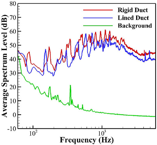
FIGURE 8. Averaged spectrum levels over the microphones in the array for the propeller with a rigid duct, a lined duct, and the background.
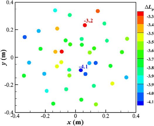
FIGURE 9. Difference in OASPL (filtered between 50 and 6,000 Hz) of the propeller at 5,100 r/min in the acoustic array.
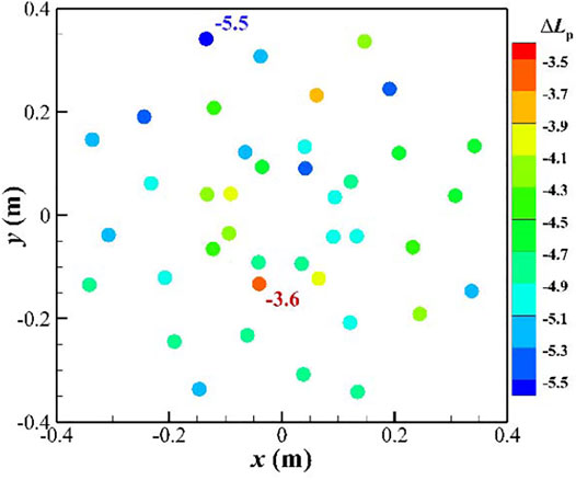
FIGURE 10. Difference in OASPL (filtered between 900 and 1,200 Hz) of the propeller at 5,100 r/min in the acoustic array.
The noise attenuation at the microphone array is close to each other. It seems that the aperture of the array is small, which means the range of the observation angle is narrow. Meanwhile, the radius of the microphone array is larger than that of the meta-liner duct. The tested results are accurate enough to describe the noise changes which are originated from the meta-liner duct.
Conclusion
In this work, a subwavelength porous meta-liner with broadband sound absorption is designed, which is composed of four subunits with different target frequencies. A hollow coiling slit with rigid walls is embedded in the porous material to build subunits as a composite structure. Then, the target frequency of sound absorption is achieved by adjusting the length of the coiling slit in each subunit. For the four designed subunits, the sound absorption coefficient is over 0.9 at the target frequency of 910 Hz, 1,000 Hz, 1,110 Hz, and 1,140 Hz, respectively. By arranging these subunits in axial direction uniformly and radial direction periodically, a meta-liner duct is built to achieve noise reduction of the ducted propeller in broadband frequency.
Finally, the change of the meta-liner duct to the overall noise of the propeller system is studied experimentally by a ring microphone array. Compared with the propeller system with a rigid duct, the meta-liner duct can reduce the noise level of the ducted propeller at broadband frequency. In particular, in the design frequency range, the propeller with the meta-liner duct can reduce the noise level between 3.6 and 5.5 dB. Therefore, our research provides an excellent method to improve the noise reduction of propeller systems with comparatively less cost, which is convenient for practical engineer applications.
Data Availability Statement
The raw data supporting the conclusions of this article will be made available by the authors, without undue reservation.
Author Contributions
HX organized and wrote the whole article. TY built the finite element model of the porous meta-liner and wrote part 2 of the article. XS and JC prepared the experiment equipment and test noise of the ducted propeller. JZ and DS analyzed the data of the experiments and wrote part 3 of the article. JG designed the structure of the ducted propeller and is responsible for its fabrication.
Funding
The authors are grateful for the financial support from the National Natural Science Foundation of China (Grant number 12072277) and the Fundamental Research Funds for the Central Universities of China (Grant numbers G2019KY05202 and G2019KY05207).
Conflict of Interest
Author JG was employed by company First Aircraft Design and Research Institute, Aviation Industry Corporation of China Ltd.,.
The remaining authors declare that the research was conducted in the absence of any commercial or financial relationships that could be construed as a potential conflict of interest.
Publisher’s Note
All claims expressed in this article are solely those of the authors and do not necessarily represent those of their affiliated organizations, or those of the publisher, the editors, and the reviewers. Any product that may be evaluated in this article, or claim that may be made by its manufacturer, is not guaranteed or endorsed by the publisher.
References
Allard, J. F., and Atalla, N. (2009). Propagation of Sound in Porous Media : Modelling Sound Absorbing Materials. 2nd edition. West Sussex: John Wiley & Sons.
Beltman, W. M., Van Der Hoogt, P. J. M., Spiering, R. M. E. J., and Tijdeman, H. (1998). Implementation and Experimental Validation of a New Viscothermal Acoustic Finite Element for Acousto-Elastic Problems. J. Sound Vibration 216, 159–185. doi:10.1006/jsvi.1998.1708
Christian, A., and Cabell, R. (2017). “Initial Investigation into the Psychoacoustic Properties of Small Unmanned Aerial System Noise,” in 23rd AIAA/CEAS Aeroacoustics Conference.
Durau, M. (2012).Acoustic Liner - Mean Flow Interaction. PhD thesis. Eindhoven, Netherland: Eindhoven University of Technology.
Fang, Y., Zhang, X., and Zhou, J. (2018). Acoustic Porous Metasurface for Excellent Sound Absorption Based on Wave Manipulation. J. Sound Vibration 434, 273–283. doi:10.1016/j.jsv.2018.08.003
Fang, Y., Zhang, X., and Zhou, J. (2018). Experiments on Reflection and Transmission of Acoustic Porous Metasurface with Composite Structure. Compos. Structures 185, 508–514. doi:10.1016/j.compstruct.2017.11.054
Guo, J., Zhou, T., Fang, Y., and Zhang, X. (2021). Experimental Study on a Compact Lined Circular Duct for Small-Scale Propeller Noise Reduction. Appl. Acoust. 179, 108062. doi:10.1016/j.apacoust.2021.108062
Kemp, C. F. B. (1932). Some Properties of the Sound Emitted by Airscrews. Proc. Phys. Soc. 44, 151–165. doi:10.1088/0959-5309/44/2/305
Kurtz, D. W., and Marte, J. E. (1970). A Review of Aerodynamic Noise from Propellers, Rotors, and Lift Fans. California: California Institute of Technology.
Li, D., Huang, S., Mo, F., Wang, X., and Li, Y. (2020). Low-frequency Broadband Absorbers Based on Coupling Micro-perforated Panel and Space-Curling Chamber. Chin. Sci. Bull. 65, 1420–1427. doi:10.1360/tb-2019-0703
Li, Y., and Assouar, B. M. (2016). Acoustic Metasurface-Based Perfect Absorber with Deep Subwavelength Thickness. Appl. Phys. Lett. 108, 063502. doi:10.1063/1.4941338
Liang, Q., Lv, P., He, J., Wu, Y., Ma, F., and Chen, T. (2021). A Controllable Low-Frequency Broadband Sound Absorbing Metasurface. J. Phys. D: Appl. Phys. 54, 355109. doi:10.1088/1361-6463/ac08cd
Liu, C., Wu, J., Yang, Z., and Ma, F. (2020). Ultra-broadband Acoustic Absorption of a Thin Microperforated Panel Metamaterial with Multi-Order Resonance. Compos. Structures 246, 112366. doi:10.1016/j.compstruct.2020.112366
Liu, H., Wu, J. H., and Ma, F. (2021). Dynamic Tunable Acoustic Metasurface with Continuously Perfect Sound Absorption. J. Phys. D: Appl. Phys. 54, 36. doi:10.1088/1361-6463/ac0ab9
Lu, Z., Debiasi, M., and Khoo, B. C. (2016). “Acoustic Characteristics of a Multi-Rotor MAV and its Noise Reduction Technology,” in INTER-NOISE and NOISE-CON Congress and Conference Proceedings.
Malgoezar, A. M., Vieira, A., Snellen, M., Simons, D. G., and Veldhuis, L. L. (2019). Experimental Characterization of Noise Radiation from a Ducted Propeller of an Unmanned Aerial Vehicle. Int. J. Aeroacoustics 18, 372–391. doi:10.1177/1475472x19852952
Mueller, T. J. (2001). Fixed and Flapping wing Aerodynamics for Micro Air Vehicle Applications. Reston, Virginia, USA: American Institute of Astronautics and Aeronautics. doi:10.2514/4.866654
Nark, D. M., and Jones, M. G. (2017). “Development of a Multi-Fidelity Approach to Acoustic Liner Impedance Eduction,” in 23rd AIAA/CEAS Aeroacoustics Conference.
Pereira, J. L. (2008). Hover and Wind-Tunnel Testing of Shrouded Rotors for Improved Micro Air Vehicle Design. Dissertations & Theses Gradworks.
Wang, Y.-F., Liang, J.-W., Chen, A. L., Wang, Y.-S., and Laude, V. (2019). Wave Propagation in One-Dimensional Fluid-Saturated Porous Metamaterials. Phys. Rev. B 99. doi:10.1103/physrevb.99.134304
Wang, Y., Zhao, H., Yang, H., Zhong, J., Zhao, D., Lu, Z., et al. (2018). A Tunable Sound-Absorbing Metamaterial Based on Coiled-Up Space. J. Appl. Phys. 123, 185109. doi:10.1063/1.5026022
Wu, F., Xiao, Y., Yu, D., Zhao, H., Wang, Y., and Wen, J. (2019). Low-frequency Sound Absorption of Hybrid Absorber Based on Micro-perforated Panel and Coiled-Up Channels. Appl. Phys. Lett. 114, 151901. doi:10.1063/1.5090355
Zhao, H., Wang, Y., Yu, D., Yang, H., Zhong, J., Wu, F., et al. (2020). A Double Porosity Material for Low Frequency Sound Absorption. Compos. Structures 239, 111978. doi:10.1016/j.compstruct.2020.111978
Zhou, J., Zhang, X., and Fang, Y. (2017). Three-dimensional Acoustic Characteristic Study of Porous Metasurface. Compos. Structures 176, 1005–1012. doi:10.1016/j.compstruct.2017.06.050
Keywords: porous meta-liner, subwavelength, duct, propeller noise reduction, finite element method
Citation: Xiao H, Yuan T, Song X, Chen J, Zhou J, Sui D and Gu J (2022) Broadband Sound Absorption of Subwavelength Porous Meta-Liner. Front. Mater. 9:845597. doi: 10.3389/fmats.2022.845597
Received: 30 December 2021; Accepted: 14 January 2022;
Published: 07 February 2022.
Edited by:
Yong Xiao, National University of Defense Technology, ChinaReviewed by:
Bu Huanxian, Hong Kong University of Science and Technology, Hong Kong SAR, ChinaChongrui Liu, Xi’an Jiaotong University, China
Copyright © 2022 Xiao, Yuan, Song, Chen, Zhou, Sui and Gu. This is an open-access article distributed under the terms of the Creative Commons Attribution License (CC BY). The use, distribution or reproduction in other forums is permitted, provided the original author(s) and the copyright owner(s) are credited and that the original publication in this journal is cited, in accordance with accepted academic practice. No use, distribution or reproduction is permitted which does not comply with these terms.
*Correspondence: Dan Sui, suidan@nwpu.edu.cn
†These authors have contributed equally to this work