Research on a Large Diameter Magnetic Fluid Seal With Thin-Wall Parts
 Yunqi Guo
 Decai Li
 Guobao Zang
 Zhiqiang Qi
 Zhili Zhang
- 1School of Mechanical, Electronic and Control Engineering, Beijing Jiaotong University, Beijing, China
- 2State Key Laboratory of Tribology, Department of Mechanical Engineering, School of Mechanical Engineering, Tsinghua University, Beijing, China
Magnetic fluid seal is a new type of sealing method, which has been applied in many fields. For some fields, such as aviation and aerospace, high sealing performance, large shaft diameter, and small design space are required, which brings difficulties to the sealing design. Therefore, it is necessary to study a large diameter magnetic fluid seal with thin-wall parts. In this article, the effects of seal clearance and shaft deflection on the magnetic field distribution of magnetic fluid seal are analyzed by the finite element method. At the same time, the force of seal shaft in the assembly process is also simulated. The influence of the amount of magnetic fluid on the pressure resistance is analyzed. The low-temperature starting torque and high-temperature pressure resistance of magnetic fluid seal are experimentally studied, and the optimal injection amount of magnetic fluid is obtained. The research content of this article can be used as a reference for the design of a large diameter magnetic fluid seal with thin-wall parts.
Introduction
Magnetic fluid (MF), also known as ferrofluid, is a new type of smart material. It comprises magnetic particles with a diameter of about 10 nm, surfactants and base carrier liquid (Li et al., 2002; Li, 2010). It is characterized by both magnetism and fluidity, which makes it irreplaceable in engineering application.
Rheology is one of the hot topics of research on magnetic fluids; for example, magnetic fluids have a magnetoviscous effect that other fluids do not have. Odenbach et al. systematically studied the rheological properties of magnetic fluid. Under the constant shear rate, the viscosity of the magnetic fluid increases with the increase of the magnetic field. They also proposed the influence of particle size on viscosity and found that the larger the particle size of magnetic particles in magnetic fluid under magnetic field, the higher the viscosity (Odenbach and Störk, 1998; Odenbach, 2000). Shah et al. showed that magnetic particles with large particle size increase the yield stress of magnetic fluids (Shah et al., 2012). Li et al. studied the thixotropic yielding behavior of magnetic fluids with different particle volume concentrations for a long enough time (Li et al., 2019).
Magnetic fluid seal is one of the most successful applications of magnetic fluid, and magnetic fluid seal has the advantages of zero leakage and long service life. The performance of magnetic fluid seals is closely related to the rheological properties of the magnetic fluid itself. The study of the frictional torque of the seal and the starting torque of the seal is one of the hot spots of magnetic fluid seal research in recent years. Li Decai et al. studied the low-temperature large-diameter magnetic fluid rotary seal and investigated the low-temperature starting torque of the magnetic fluid seal with an operating temperature of −40°C. The factors affecting the starting torque of the seal were systematically studied (Li et al., 2001; Li et al., 2004). Chung kyun kim et al. investigated the frictional torque of magnetic fluid seal with different pole tooth shapes and parameters (Kim and Kim, 1997). He xinzhi et al. showed that the yield stress is one of the main factors affecting the pressure resistance and starting torque of magnetic fluid seal (He et al., 2015). Zhixin studied the variation of starting torque of the magnetic fluid seal with the resting time. It was found experimentally that the starting torque of the seal increased with the increase of the resting time and then tended to saturate (Li, 2002). They attributed the abovementioned phenomenon to the magnetic fluid film under the magnetic field in which the Cai et al. found that large magnetic particles and low temperature environment would change the microstructure of magnetic fluid and proposed a method to reduce the large size particles in the magnetic fluid (Cai and Xing, 2013). Chen et al. found that the magnetic fluid seal starting torque would increase sharply with the decrease of temperature through the experimental study (Chen et al., 2018). Cheng Yanhong et al. studied the factors affecting the starting torque of fluoroether oil-based magnetic fluid seals (Cheng et al., 2021). Thus, it can be seen that the starting torque of magnetic fluid seals is one of the key points of the seal research.
The magnetic fluid seal faces various design problems in the environment of limited space. For example, how to design the distribution of magnetic field strength, the influence of installation accuracy and deformation of thin-walled parts on the magnetic field, and the size of magnetic field force during the assembly should be studied on the design basis. In this article, the abovementioned problems are simulated by ANSYS Maxwell software. The simulation results show that the large-diameter thin-wall magnetic fluid sealing structure has guiding significance.
Theory
Theory of Pressure Resistance of Magnetic Fluid Seal
Sealing is the most extensive and successful application of magnetic fluid in engineering. It has outstanding advantages of zero leakage, long service life, and high reliability, especially in vacuum containers, vacuum pumps, and other vacuum sealing effects. The basic structure of magnetic fluid seal is composed of rotating shaft, pole shoe, permanent magnets, and magnetic fluid, as shown in Figure 1.
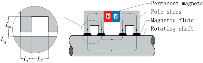
FIGURE 1. Magnetic fluid seal structure.
Under the action of the magnetic field, the magnetic fluid forms liquid rings similar to “O” rings in the gap between the pole teeth and the shaft so as to play a sealing role.
The biggest difference between the magnetic fluid and other fluids is its response to the magnetic field, which is also reflected in the Bernoulli equation. The Bernoulli equation of general fluid is
Rosensweig derived the Bernoulli equation of magnetic fluid (Rosensweig, 1985; Li, 2010):
Compared with the Bernoulli equation of general fluid, magnetic fluid has one more magnetic energy product term, so the flow characteristics of magnetic fluid are more complex than those of the general fluid, and it also has irreplaceable applications in engineering.
For the calculation of pressure resistance of magnetic fluid seal, it is assumed that the gravity and magnetic force of magnetic fluid are relatively small and can be ignored; The magnetic field line can be approximately replaced by an arc, and the equal magnetic field line coincides with the magnetic field line; the surface tension of the magnetic fluid is ignored. At this time, the pressure resistance of magnetic fluid single-stage seal is
Torque of Magnetic Fluid Seal
Unlike traditional contact seals, such as packing seals and mechanical seals, magnetic fluid seals have no solid friction, so their friction torque is low and there is no wear. However, under the strong magnetic field or low temperature conditions, the rheological properties of magnetic fluid will change obviously, which affects the application of magnetic fluid seal. Therefore, it is necessary to study the torque of magnetic fluid seal. Magnetic fluids usually behave like H-B fluids under the action of a magnetic field (Rosensweig, 1985; Yang et al., 2006; Hong et al., 2007; Li et al., 2019), so we assume that:
where τ is the shear stress,
where F is the minimum value of the force that allows the shaft to rotate, r1 is the radius of the rotating shaft, and S is the area of the contact surface between the shaft and the magnetic fluid. The surface area S is given by
where ω is the speed of the shaft, Lt is the width of the pole teeth, Lg is the width of the sealing gap, and N is the number of the pole teeth.
Force Calculation Method of Magnetic Fluid Seal Rotating Shaft
Electromagnetic calculation is a part of the design of magnetic fluid seal and one of the important bases for the normal operation of equipment. There are two classical electromagnetic force calculation methods, Maxwell stress method and the virtual displacement method. For the virtual displacement method, according to the principle of virtual work, the force on the object in the Q direction is (Yan et al., 2003; Mingli et al., 2007; Yang et al., 2009):
where Wm is the magnetic field energy of the system,
For Maxwell’s stress method, it usually starts from Maxwell’s stress constant T.
T is a second-order tensor in which the elements are
where
Then, the combined force acting on the magnetic mass is
where S is any one of the closed surface surrounding the magnetic mass, S is usually set in the air around the magnetic mass, and for a two-dimensional problem, this area fraction is reduced to a closed curve, and the combined force F can be expressed as
where t and n are the tangential and normal unit vectors of the integration path, respectively.
Magnetic Field Simulation and Analysis
Modeling and Magnetic Field Analysis in the Ideal State
The key factor in the design of magnetic fluid seal is the magnetic field design, which is directly related to the pressure resistance of the seal. Ideally, the sealing clearance of the magnetic fluid seal is 0.1mm, which is guaranteed by the bearings installed on both sides of the pole shoe. For a large-diameter magnetic fluid seal, the installation accuracy of thin-walled shaft has a significant impact on the pressure resistance of magnetic fluid seal. At the same time, thin-walled parts are easy to deform during transportation, assembly, and loading. Therefore, it is very necessary to study the pressure resistance of thin-walled parts under deformation.
The design requirements of the seal are the radius of the shaft r1 = 173 mm and the shaft width is 18 mm, and the seal pressure resistance is not less than 0.08 MPa in the temperature range of -55–70°C.
The magnetic field strength (H) and magnetic flux density (B) at the seal gap can be obtained quickly and accurately by simulation using ANSYS Maxwell. First, a simplified calculation of the magnetic fluid seal structure is performed. It is assumed that the magnetic permeability of the non-magnetic material parts such as bearings, bearing seats, and end caps is 1; the relative permeability of the magnetic fluid is much smaller than the relative permeability of the material of the rotating shaft and the pole shoe, so it is assumed that the magnetic fluid has a permeability of 1; and the magnetic field provided by multiple sets of cylindrical magnets is assumed to be uniformly distributed. Based on the abovementioned assumptions, the simulation model can be simplified to Figure 2, and the three-dimensional problem can be simplified to a two-dimensional problem. Since the magnetic permeability of parts such as bearings is assumed to be 1, which is always the same as that of the air domain, these parts can be ignored in this analysis.
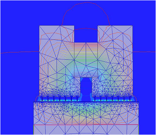
FIGURE 2. Cloud diagram of magnetic field strength at 0.1 mm sealing gap.
The following is a description of the finite element simulation modeling: the material used for the pole shoe and the shaft is 2Cr13 with a relative permeability of 4,000; the permanent magnet is N35 with a relative permeability of 1.1, and a coercivity of 890 kA/m. The saturation magnetization strength of the magnetic liquid is 450Gs; each pole shoe has seven pole teeth, and a total of 14 pole teeth are designed with a width of 0.2 mm and a height of 0.7 mm, and the distance between the two adjacent pole teeth is 0.8 mm. Since the ratio of axial constancy to the radial length is 0.052 for the seal structure analyzed in this article, the seal structure is a large diameter thin-wall magnetic fluid seal. At the sealing gap, we set the maximum length of the element to 0.01 mm, we set the maximum number of passes to 10, the percentage error to 1, and the optimal pass rate to 30%, the maximum number of passes as 10, percent error as 1, and refinement per pass as 30%.
First, the magnetic field in the ideal state of magnetic fluid seal is analyzed, and the magnetic field strength of the model can be obtained through calculation. The cloud diagram of magnetic field intensity after analysis is shown in Figure 2, and the distribution of magnetic field intensity under the polar teeth is shown in Figure 3. Assuming that the magnetic fluid is in the best working position when receiving the pressure, the coordinates of the highest point and the lowest point are taken and the pressure resistance of the seal as 0.28 MPa is calculated according to the formula (Odenbach and Störk, 1998).

FIGURE 3. Magnetic field intensity distribution in the sealing gap at 0.1 mm sealing gap.
Analysis of Magnetic Field Forces During Assembly
In the assembly of magnetic fluid seal, the two pole shoes and permanent magnet are generally assembled before installation. During installation, due to the magnetic force, the pole shoe and the rotating shaft attract each other, resulting in eccentricity, which eventually leads to the hanging of the pole teeth and the shaft during installation, which will seriously lead to the deformation and damage of the pole teeth. Therefore, it is necessary to explore the magnetic force on the shaft sleeve during installation. The axial force of the shaft sleeve can be calculated by changing the x-axis coordinate of the shaft sleeve and using the energy gradient method or Maxwell stress tensor. It can be seen from the calculation results that the force received is quasi periodic, as shown in Figure 4, which is caused by the polar tooth structure. According to the calculation results, the maximum value is 1.436 kN.
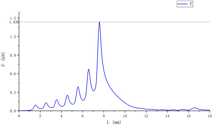
FIGURE 4. Axial magnetic field force on the rotating shaft.
In the practical application of magnetic fluid seals, most magnetic fluid seals require custom designs, except for standard parts from companies such as Ferrotec. In addition, most magnetic fluid seals are small-diameter seals, so manual assembly is sufficient to meet the assembly accuracy requirements. However, for large-diameter thin-walled magnetic fluid seals, the abovementioned study shows that the axial force during the assembly is up to 1.436 kN, which makes manual assembly impossible to ensure that the process is free from scratches and knocks. In order to solve the abovementioned problem situation, a large diameter fixture should be designed to fit the assembly. The principle is to ensure the coaxiality between the machine shoe and the rotating shaft in the assembly by the clearance fitting surface of the upper and lower fixture. The axial distance during assembly is adjusted by screws, and the installation of sealing parts is completed under the premise of ensuring the coaxiality, thus effectively avoiding scraping and collision caused by the magnetic field force.
Analysis of the Effect of Different Parameters on the Seal
The thin-wall parts are prone to deformation during machining, especially for large-diameter thin-walled shafts. Therefore, it is necessary to study the effect of different sealing clearances on the pressure resistance and thus use it as a basis for designing the tolerance of the pole shoes and the rotating shafts. This research can play a key role in the design of thin-wall seals.
As can be seen from Figures 5, 6, the pressure resistance of the seal decreases significantly with the increase of the seal clearance. When the sealing gap is greater than 0.6 mm, the pressure resistance of the seal is 0.0241 MPa, which is less than 1/10 of that when the sealing gap is 0.1 mm. It can be considered that when the sealing gap is greater than 0.6, the magnetic fluid seal has no sealing ability and the seal fails. It is worth mentioning that when the thin-walled rotating shaft is deformed due to the force, the shape of the shaft will change, and the magnetic fluid seal gap under the pole teeth will be uneven. Here, the change of magnetic field strength caused by the shaft deformation is ignored, and the maximum value of sealing gap at each level is taken to calculate the pressure resistance. Similarly, this method can be used to calculate the pressure resistance, when the bearing runout is large or when the accuracy of the shape tolerance is low.
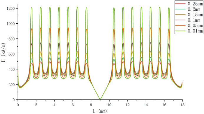
FIGURE 5. Distribution of sealing magnetic field strength under different sealing gaps.
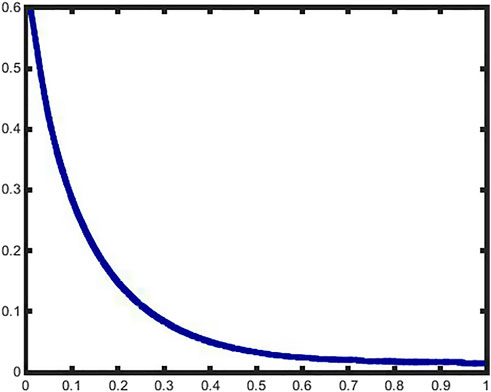
FIGURE 6. Relationship between the sealing gap and sealing pressure resistance.
The sealing structure studied in this article has 14 pole teeth, and the actual requirement of sealing is 0.08 MPa, and the sealing medium is nitrogen or dry air. When the sealing gap is larger than 0.31 mm, the theoretical pressure resistance is 0.0791 Mpa, and the sealing performance cannot meet the design requirements at all. When the seal gap is 0.1 mm, the theoretical pressure resistance is 0.2854 Mpa, and this value is consistent with the design experience. If the magnetic field design requires that the pressure resistance should be 2.5 times larger than that of the application, which means that the pressure resistance is not less than 0.2 Mpa, it is known from the simulation results that the seal gap should not be larger than 0.15 mm. The simulation results are not only applicable to the design of the seal structure but also can be used to analyze the pressure resistance after the deformation of the thin-walled sleeve or to analyze the effect of the eccentricity of the sleeve, that is, for the cumulative tolerance offset of the design on the radius should not be greater than 0.05 mm.
If the shaft is subjected to radial forces, the shaft may also be deflected, so it is necessary to study the magnetic field intensity distribution when the pole shoe is not parallel to the shaft. By calculation, for this sealing mechanism, the shaft and the pole shoe will contact when the shaft is rotated by 0.66°, so this research studies the change of magnetic field intensity distribution, when the rotation shaft deflection angle is from 0° to 0.66°, and obtains the effect of deflection angle on the seal pressure resistance.
As can be seen from Figure 7, the magnetic field intensity under the right pole shoe increases significantly with the increase of deflection angle, and the magnetic field intensity under the left pole shoe decreases with the increase of deflection angle. In this article, the three-dimensional problem is simplified into a two-dimensional model, so the value of the minimum magnetic field strength under each pole tooth should be taken after calculating the sealing pressure resistance. Through calculation, the relationship between different rotation angles and sealing pressure resistance can be obtained in Figure 8. The results show that the pressure resistance of the seal decreases with the increase of the deflection angle of the rotating shaft. It should be noted that the maximum deflection angle is 0.66°, and the calculated sealing pressure resistance is 0.2045 Mpa. Compared with the deflection angle of 0, the sealing pressure resistance is 0.02853 Mpa, a decrease of 28.3%. However, this does not mean that the deflection of the shaft has less influence on the seal. Considering the bearing life and seal life, the design and assembly should still minimize the deflection angle of the rotating shaft.
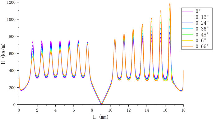
FIGURE 7. Effect of different rotation angles of the shaft on the distribution of magnetic field strength.
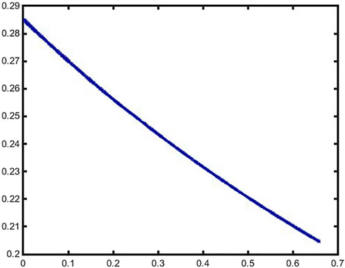
FIGURE 8. Relationship between different rotation angles of the shaft and the pressure resistance.
Under normal assembly conditions, an overfilling of magnetic fluid should be injected to ensure a long life of the magnetic fluid seal. However, excess magnetic fluid will increase the sealing torque, a problem that is not significant in ambient temperature environments. However, if there is a need for low temperature sealing, such as in a −55°C environment, the start-up torque of the magnetic fluid seal will increase significantly, which may cause damage to the motor and other components. If there is a strict requirement for the rotational torque of the seal, it is necessary to study the relationship between the volume of the magnetic fluid and the pressure resistance. In the seal gap, the distribution interface of the magnetic fluid will coincide with isomagnetic lines. To facilitate the calculation, the isomagnetic lines is reduced to a circular arc, as shown in Figure 9.
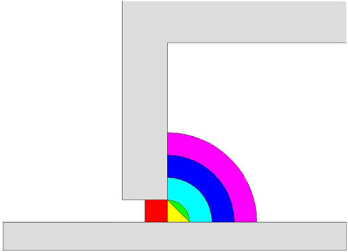
FIGURE 9. Distribution of magnetic fluid under the polar teeth.
The abovementioned analysis results are calculated based on the finite element magnetic field strength analysis. According to the abovementioned curve, when the volume of magnetic fluid reaches 0.6 ml, the pressure resistance reaches 0.27 MPa, which is only a theoretical decrease of 3.5% compared to the pressure resistance of an excess of magnetic fluid, as shown in Table 1 and Figure 10. Therefore, it can be assumed that the volume of magnetic fluid seal used in this study is at least 0.6 ml. It is worth discussing that in the general assembly process of magnetic fluid seal, it is usually necessary to inject an excess amount of magnetic fluid and only a small amount of magnetic fluid is adsorbed at the pole teeth. Also, due to different assembly processes, the magnetic fluid may be adsorbed directly on the permanent magnet, resulting in waste. Therefore, it is necessary to explore a new magnetic fluid seal structure and its assembly method.

TABLE 1. Relationship between the volume of magnetic fluid and pressure resistance.
FIGURE 10. Effect of different volumes of magnetic fluid on the pressure resistance of the seal.
Experimental Analysis
Experimental conditions: after holding at −55°C for 2 hours, conduct low temperature sealing pressure and low temperature starting torque test. After heating to 70°C and holding for 2 hours, the high-temperature pressure resistance test is conducted.
Experimental equipment: high- and low-temperature environmental chamber.
Test method. Measure the length of the long rod connected to the rotating shaft with an arm length of L. Hang a bucket on one end of the long rod and add the weights slowly and sequentially to the bucket. The weight m is measured after the rotating axis is rotated. The starting torque is calculated according to the following formula:
The graph below shows the relationship between the magnetic fluid volume and the low temperature start-up torque of the magnetic fluid seal at a low temperature of −55°C. The viscosity and yield stress increase as the temperature decreases. Also, the viscosity and yield stress of the magnetic fluid increase with increasing magnetic field strength due to the response of the magnetic fluid to the magnetic field. Therefore, for magnetic fluid in large diameter magnetic fluid seal, the magnetic force in the seal gap is very high. At a low temperature of −55°C, the viscosity and yield stress of the magnetic fluid increase significantly. This leads to a significant increase in the low temperature start-up torque of the magnetic fluid seal compared to that at the room temperature and high temperature. The relationship between the magnetic fluid injection volume and the low-temperature start-up torque of a large-diameter magnetic fluid seal was investigated. The experimental results are shown in Figure 11. With a magnetic fluid volume of 3 ml, the start-up torque of the seal can be as low as 30 Nm at a sealing pressure of 0.08 MPa. The pressure does not decrease after the seal is rotated. The results show that the low-temperature starting torque of the large-diameter magnetic fluid seal increases with the increase of the magnetic fluid volume. It should be noted that the lubrication performance of the magnetic fluid seal bearing is poor at low temperature, which also affects the starting torque and rotating torque. When the volume of the magnetic fluid is less than 3 ml, the magnetic fluid seal will leak above 70°C. Therefore, in the design, it is necessary to consider both the connection of reducing the low-temperature starting torque and the high-temperature seal failure. Large diameter magnetic fluid seal with thin-walled parts are shown in Figure 12.
FIGURE 11. Magnetic fluid volume versus starting torque in −55°C environment.

FIGURE 12. Large diameter magnetic fluid seal with thin-walled parts.
Since there is no rheometer dedicated to measure the yield stress of magnetic liquids in −55°C, the calculation can be performed by equation (7). The starting torque of the seal is measured with a small rotational speed of the rotating shaft, ω ≈ 0,N = 14, r1 = 173 mm, Lt = 0.2 mm, and T = 30 Nm. Thus, we obtained the yield stress of the magnetic liquid in a strong magnetic field after 2 hours of holding at −55°C. The yield stress ts = 57 kPa.
Conclusion
Based on the principle of magnetic fluid seal, the influencing factors of magnetic field distribution of a large-diameter thin-walled magnetic fluid seal are studied by the finite element method, and the low-temperature starting torque of magnetic fluid seal is studied by the experiment.
1) The pressure resistance formula of magnetic fluid seal, the torque of magnetic fluid, and the force on the rotating shaft of magnetic fluid seal are analyzed.
2) Through the finite element analysis method, the magnetic field force of the rotating shaft of large-diameter magnetic fluid seal during the assembly is simulated and analyzed.
3) The influencing factors of magnetic field distribution in magnetic fluid seals were analyzed by the finite element method. The effects of seal gap and shaft deflection angle on the magnetic field distribution in the magnetic fluid seal gap were analyzed to help the tolerance design of the parts.
4) The effect of magnetic fluid volume on the pressure resistance of magnetic fluid seal is analyzed.
5) The effect of the volume of the magnetic fluid on the low-temperature starting torque and the pressure resistance of the magnetic fluid seal was analyzed by the experiment.
Data Availability Statement
The raw data supporting the conclusion of this article will be made available by the authors, without undue reservation.
Author Contributions
YG and DL conducted the theoretical study and finite element simulation study of magnetic fluid seal. YG, DL, GZ, ZQ, and ZZ have participated in the experimental study of the starting torque of the seal in the low-temperature environment.
Funding
This work was supported by the National Natural Science Foundation of China (Grant Nos. 51735006, 51927810, and U1837206) and Beijing Municipal Natural Science Foundation of China (Grant No. 3182013).
Conflict of Interest
The authors declare that the research was conducted in the absence of any commercial or financial relationships that could be construed as a potential conflict of interest.
Publisher’s Note
All claims expressed in this article are solely those of the authors and do not necessarily represent those of their affiliated organizations, or those of the publisher, the editors, and the reviewers. Any product that may be evaluated in this article, or claim that may be made by its manufacturer, is not guaranteed or endorsed by the publisher.
References
Cai, Y. Q., and Xing, N. (2013). The Analysis on the Starting Friction Torque Increase of Magnetic Fluid Revolving Sealing. Amm 275-277, 429–432. doi:10.4028/www.scientific.net/amm.275-277.429
Chen, J., Li, D., and Hao, D. (2018). Investigation on the Influence of Temperature on Starting Torque of Magnetic Fluid Seal. J. Magneics 3 (23), 436–441. doi:10.4283/jmag.2018.23.3.436
Cheng, Y., Li, D., and Li, Z. (2021). Influence of Rheological Properties on the Starting Torque of Magnetic Fluid Seal. IEEE Trans. Magn. 57 (3), 1–8. doi:10.1109/tmag.2019.2934716
He, X., Li, D., and Hao, R. (2015). The Influence of Magnetic Fluid Yield Stress on the Performance of Magnetic Fluid Seal. Acta Armamentarii 36 (01), 175–181. doi:10.3969/j.issn.1000-1093.2015.01.025
Hong, R. Y., Ren, Z. Q., Han, Y. P., Li, H. Z., Zheng, Y., and Ding, J. (2007). Rheological Properties of Water-Based Fe3O4 Ferrofluids. Chem. Eng. Sci. 62 (Issue 21), 5912–5924. doi:10.1016/j.ces.2007.06.010
Kim, C. K., and Kim, H. G. (1997). A Study on the Friction Torque and Temperature Distribution of Magnetic Fluid Seals. Trans. Korean Soc. Mech. Eng. A 21 (1), 53–61. doi:10.22634/KSME-A.1997.21.1.53
Li, D., Hong, J., and Yang, Q. (2002). The Study on the Magnetic Fluid Sealing of Dry Roots Pump. Vac. Sci. Technol. 22 (04), 78–81. doi:10.13922/j.cnki.Cjovst.2002.04.019
Li, D., Xu, H., Liao, P., and Cui, H. (2004). Study on the Breakaway Torque of Magnetic Fluid Sealing at Low Temperature and Large Diameter. J. Funct. Mater. 35, 566. doi:10.3321/j.issn:1001-9731.2004.z1.150
Li, D, Xu, L, Wang, Q, and Chui, H (2001). “Study of low temperature and large diameter magnetic fluid rotatory sealing,” in Proceedings of the 4th China Academic Conference on Functional Materials and Applications; 2001, 568, Xiamen, China, Ocotober 1, 2001.
Li, Z., Li, D., Chen, Y., Guo, Y., and Zhang, Z. (2019). Thixotropic Yielding Behaviors of Ferrofluids. J. Magnetism Magnetic Mater. 486, 165277. doi:10.1016/j.jmmm.2019.165277
Li, Z., Li, D., Cui, H., Zhang, Y., and Wang, H. (2019). Influence of the Carrier Fluid Viscosity on the Rotational and Oscillatory Rheological Properties of Ferrofluids. J. Nanosci. Nanotechnol., 19, 5572–5581. doi:10.1166/jnn.2019.16525
Li, Z. (2002). Magnetic Fluid Seals for DWDM Filter Manufacturing. J. Magnetism Magnetic Mater. 252 (1-3), 327–329. 2002-01-01. doi:10.1016/s0304-8853(02)00681-9
Mingli, S., Decai, L., Xinzhi, H., and Ruican, H. (2007). Simulation and Design of Magnetic Fluid Sealing Devices. Chin. J. Vac. Sci. Technol. 27 (03), 269–272. 2007-05-15. doi:10.3969/j.issn.1672-7126.2007.03.021
Odenbach, S., and Störk, H. (1998). Shear Dependence of Field-Induced Contributions to the Viscosity of Magnetic Fluids at Low Shear Rates. J. Magn. Magn. MATER 183 (1-2), 188–194. doi:10.1016/s0304-8853(97)01051-2
Odenbach, S. (2000). Magnetoviscous Effects in Ferrofluids. Appl. Rheol. 10 (4), 178–184. doi:10.1515/arh-2000-0011
Shah, K., Upadhyay, R. V., and Aswal, V. K. (2012). Influence of Large Size Magnetic Particles on the Magneto-Viscous Properties of Ferrofluid. Smart Mater Struct. 21 (7), 75005. 2012-07-01. doi:10.1088/0964-1726/21/7/075005
Yan, X., Xie, D., Gao, Z., and Yu, C. (2003). Research on Integration Path Selection of Maxwell Stress Tensor Method Used in Electromagnetic Force FEM Analysis. Trans. China Electrotech. Soc. 18 (05), 32–36. doi:10.3321/j.issn:1000-6753.2003.05.007
Yang, W., Li, D., Cai, Y., Huang, Y., and Li, Q. (2009). Numerical Calculation of Magnetic Field and Magnetic Force Exerted on the Shaft with Eccentricity in Magnetic Fluid Seal. Lubr. Eng. 34 (12), 48–51. doi:10.3969/j.issn.0254-0150.2009.12.013
Keywords: magnetic fluid, magnetic fluid seal, large diameter, thin-wall parts, finite element simulation
Citation: Guo Y, Li D, Zang G, Qi Z and Zhang Z (2022) Research on a Large Diameter Magnetic Fluid Seal With Thin-Wall Parts. Front. Mater. 9:932662. doi: 10.3389/fmats.2022.932662
Received: 30 April 2022; Accepted: 22 June 2022;
Published: 05 August 2022.
Edited by:
Yang Yu, Western Sydney University, AustraliaReviewed by:
Stefano Giordano, Institut d'électronique, de microélectronique et de nanotechnologie (IEMN), FranceYoshinori Mitamura, Hokkaido University, Japan
Copyright © 2022 Guo, Li, Zang, Qi and Zhang. This is an open-access article distributed under the terms of the Creative Commons Attribution License (CC BY). The use, distribution or reproduction in other forums is permitted, provided the original author(s) and the copyright owner(s) are credited and that the original publication in this journal is cited, in accordance with accepted academic practice. No use, distribution or reproduction is permitted which does not comply with these terms.
*Correspondence: Decai Li, lidecai@mail.tsinghua.edu.cn