Design selection and dynamic response analysis of CFG pile composite foundation in soft soil areas
 Huahua Zhang
 Liming Liu1,2
  Bingqin Zhao
- 1Hubei Provincial Engineering Research Center of Slope Habitat Construction Technique Using Cement-based Materials, China Three Gorges University, Yichang, China
- 2College of Civil Engineering and Architecture, China Three Gorges University, Yichang, China
- 3Housing and Urban-Rural Development Bureau, Yichang, China
- 4The Seventh Geological Brigade of Hubei Geological Bureau, Yichang, China
The construction of roads along rivers plays a crucial role in the construction of economic belts and social and economic development along rivers. Roadbeds are the foundation of highway construction, while the soft soil foundation is widely distributed on both sides of rivers, resulting in some difficulties for roadbed construction and highway use. Despite diverse technical methods for the treatment of general roadbeds, the treatment of soft soil roadbeds should be further explored. In this paper, various advantages of applying CFG (Cement Fly-ash Gravels) pile treatment to the soft foundation in Bailinhe Road, Yichang are investigated. Specifically, the soft soil roadbed treated by CFG pile is numerically simulated, the changes in engineering index response before and after foundation treatment are analyzed, and then the dynamic analysis under vehicle dynamic load is performed. The results demonstrate that the reinforcement effect of the CFG pile significantly weakens the influence of vehicle dynamic load on roadbeds.
1 Engineering background
Influenced by the rise and fall of river water level, the roadbed of Bailinhe Road in Yichang City has complicated geological and hydrological conditions (Cui et al.,2022). If the roadbed is treated by the conventional roadbed treatment method, it would not reach the design bearing capacity during construction and compaction, and it is easy to cause uneven settlement after construction (Bai et al., 2021a). The existing data theory and processing methods have some limitations (Bai et al., 2021b). Nevertheless, the requirements of national general norms are still adopted, and the targeted theoretical research and analysis are not conducted in the combination with the particularity of the region (Jones Jr, 1981; Cui et al.,2019). Therefore, a comprehensive theoretical analysis based on engineering geology and hydrology conditions in Yichang should be conducted to propose corresponding treatment measures and lay a theoretical basis for the treatment of similar special soil foundations (Peng et al., 2016; Yin and Yu, 2009; Bai et al.,2022). Besides, the roadbed, as the foundation of the road, is the prerequisite to guarantee the high-speed, smooth, comfortable, and safe operation of vehicles. Hence, the deformation and dynamic issues of soft soil roadbeds under dynamic loads are crucial in road roadbed engineering (Tan, 1995; Bai et al.,2019).
Currently, researchers around the world have conducted a lot of studies on the dynamic response and reinforcement of roadbeds under dynamic loads and achieved a series of achievements (Derbyshire et al., 1994; Bai et al.,2020). For example, Zhao Guotang and Liang Bo et al. simplified the superstructure and established a roadbed model under the consideration of the relationship between each structure layer and the dynamic response characteristics of roadbeds. Xu Peng et al. investigated the dynamic response caused by vehicles’ dynamic loads using the dynamic model and then provided the longitudinal and transverse distribution of dynamic deformation and dynamic stress along roadbeds. Chen Renpeng et al. discussed the influence of vehicle speed on the mean value and variation coefficient of dynamic stress based on the roadbed roughness and then established two-dimensional and three-dimensional analysis models of roadbed structures. Since the particularity of soft soil engineering properties makes the dynamic characteristics of soft soil roadbeds complicated, the stability induced by dynamic response is also concerned (Terzaghi, 1943; Habibagahi and Mokhberi, 1998). Although many research achievements on the dynamic response of roadbeds have been obtained, there are few studies on the reinforcement effect of soft roadbeds (Alamgir et al., 1996; Otani et al., 1998). Moreover, the roadbeds built on soft soil generally need reinforcement in the actual engineering due to an insufficient foundation bearing capacity, and CFG pile reinforcement is one of the effective methods (Jung et al.,2001; Lai et al., 2016). The three-dimensional finite element method was employed to analyze the effect after CFG pile reinforcement and the variation rules of vertical velocity, acceleration, and compressive stress based on the roadbed reinforcement engineering of Bailinhe Road, Yichang City. The simulation results are of great significance for promoting the development of foundation treatment technology for soft soil roadbed engineering (Ye and Gong, 2017; Cheng et al., 2018).
2 Roadbed settlement calculation
Soil masses are compressible, and foundation settlement is inevitable during construction. Foundation settlement generally includes three parts: Instantaneous settlement, primary consolidation settlement, and secondary consolidation settlement. Instantaneous settlement occurs in the initial stage and is provoked by the deformation of the soil skeleton and elastic deformation of the soil. Secondary consolidation settlement occurs in the final stage and results from the creep of soil. Primary consolidation settlement is the most concerned. The settlement in a general sense indicates the primary consolidation settlement and is generated by the drainage of excess pore water in the soil particle clearance and the change in the soil void. In practice, the three kinds of settlements are not completely independent, and there are frequently multiple settlement components simultaneously, while one of them occupies a higher proportion.
The deformation settlement of soft soil roadbeds has two characteristics: A large amount of deformation and a long duration of deformation settlement. Instantaneous settlement and secondary consolidation settlement usually adopt estimation, while main consolidation settlement adopts more theoretical calculation methods. Appropriate calculation methods should be employed to handle specific issues. Under the Winkler model, the settlement of a certain point on the foundation is related to the pressure of soil action at that point, rather than the pressure of other points. With regard to the foundation with similar mechanical properties to water, such as the semi-liquid soil with very low shear strength (such as silt, soft clay) or the plastic zone under a relatively large foundation, the winkle elastic foundation beam method is considered to be more appropriate for soft foundation reinforcement treatment, and the composite stiffness method is more suitable for the composite foundation treatment.
In China, the calculation of foundation settlement is primarily performed by the layerwise summation method, which is clear in theory, simple in the calculation, and easy to obtain the calculation parameters. The calculation results are consistent with the actual situation. Unfortunately, the influence of soil lateral deformation is neglected.
The volume of soil particles for single-layer soil masses remains unchanged before and after compression, as Formula (1):
Therefore, the settlement value can be obtained following the e-p curve as Formula (2):
Finally, the sum of all layers of soil is utilized to acquire the final settlement expression, as Formula (3)
Where Vs. represents the initial volume, e1 indicates the initial porosity ratio, e2 denotes the compressed pore ratio, H refers to the thickness of the soil, A means the area of the soil, s stands for the height of settlement, a represents the compression coefficient, Δp means the average additional stress applied to the soil layer, and Es denotes the amount of compressed soil.
3 Cement fly-ash gravels pile reinforcement mechanism
Cement Fly-ash Gravel (CFG) pile is a high-strength bonded pile formed by cement, gravel, fly ash, stone debris, and water through the long Auger pipe pump pressure into the pile in the foundation drilling perfusion. CFG pile composite foundation is composed of the pile body, the soil between piles, and the cushion layer. CFG piles are widely used in the treatment of soft soil foundations owing to their characteristics of simple construction, significant improvement of foundation bearing capacity, green environmental protection, low economic cost, and strong applicability.
CFG pile generally reinforces the foundation through compaction, restraint, and drainage consolidation between piles and the soil.
1) CFG pile body. Since the pile strength and elastic modulus in the CFG pile composite foundation are significantly greater than those of the soil between piles, the CFG pile body shares most of the upper pile load, improves the overall foundation stiffness, and reduces the roadbed settlement.
2) Compaction. The soil particles become compact through the construction vibration and impact of the CFG pile, leading to a decrease in the soil pore ratio and water content, an increase in the soil weight, and an improvement in the bearing capacity of the foundation.
3) Constraint effect. CFG piles can limit the lateral deformation of the soil between piles, maintain the interaction between piles and the soil, and weaken the roadbed settlement.
4) Drainage consolidation. CFG pile body and cushion, with good water permeability, can be used as the foundation drainage channel to accelerate the consolidation settlement after foundation construction.
5) Cushion. The cushion can lower the stress concentration of the bottom of the foundation, adjust the proportion of pile to soil to share the upper load, provide conditions for CFG pile penetration, and assure the cooperation of the pile body and the soil between the piles.
4 Analysis of reinforcement effect of cement fly-ash gravels pile on soft foundation
Foundation survey data reveal that the foundation soil contains silty clay, silt soil, gravel soil, and containing-gravel silty clay from shallow and deep. Based on the comprehensive consideration of the engineering geology, the replacement has not been economic enough and fails to satisfy the requirement of the time limit for engineering. Therefore, CFG pile treatment can be employed to guarantee the construction progress and make the roadbed rapidly consolidate. The depth of soft soil in highway roadbeds is 5–10 m, and it is brown soft clay, with high moisture content and large compressibility. Hence, there is a large settlement and risk of embankment instability.
4.1 Establishment and parameter selection of finite element model
Foundation survey data suggest that the foundation soil contains silty clay, silt soil, gravel soil, and containing-gravel silty clay from shallow and deep. Based on the comprehensive consideration of the engineering geology, the replacement has not been economic enough and cannot meet the requirement of the time limit for engineering. Therefore, it is feasible to adopt CFG pile treatment to guarantee the construction progress and make the roadbed rapidly consolidate.
Plaxis software was used for two-dimensional numerical modeling. Method 1: Plate element method is adopted. The disadvantage of this method is that it ignores the seepage in plate element, but it is relatively easy to calculate the bending moment, shear force and axial force. Method 2: Solid element method is adopted to calculate the solid element parameters of 2-days pile based on the equivalence of stiffness, weight and permeability coefficient. Besides, permeability is taken into account. However, the bending moment, shear force and axial force are not obtained directly. They can only be calculated by using the stress on the pile. Considering that the highway has a symmetrical structure, half of the structure was used for modeling analysis, and the actual design values were selected for the geometric parameters of the model. The 2D model of the highway cross-section was established with a 10 m-deep soft soil base and a 10 m-deep bearing layer foundation. The sheet element was utilized to simulate the pile, and the pile length was 11 m according to the design. Then, it traversed the soft soil area and was embedded in 1 m under the bearing layer. The pile spacing was 1.4m, and the pile diameter was 0.4 m. The mechanical properties of the CFG pile are presented in Table. 1. The geological survey report did not provide the more detailed parameters of the foundation soil. Thus, the highway filling was filled with gravel soil, the stratified construction with a thickness of 0.5 m was conducted, and the bottom of the embankment adopted a 0.4 m-thick gravel cushion, so as to simplify the model and fully consider the unfavorable factors of the soft soil foundation. The parameters of the highway soil body are listed in Table. 2. Moore-coulomb soil constitutive model and Goodman contact element without thickness were utilized to simulate pile-soil interaction, and then the strength reduction was used for the interface element.

TABLE 1. Mechanical parameters of CFG pile.
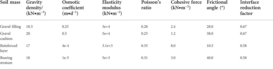
TABLE. 2. Parameters of the soil mass.
The highway embankment is 5 m high, 27 m wide at the top, and 42 m wide at the bottom. The embankment slope rate is 1:1.5. Besides, the modeling range is 50 m in width and 25 m in depth to avoid any influence on numerical results due to the geometric size of the model. Standard boundary conditions were applied to the boundary, with horizontal constraints for the left and right sides, and complete constraints for the bottom. Meanwhile, the influence of water level on the model was ignored.
4.2 Displacement result analysis of reinforced foundation
As demonstrated in Figure 1A, B, the foundation settlement after CFG pile treatment decreased from 253.25mm to 107.23mm, with a decrease of about 57.66%. In other words, the CFG pile significantly improved the stiffness of the soft soil foundation and effectively reduced the settlement caused by insufficient foundation stiffness. In Figure 1C, compared with the case without foundation treatment, the uneven settlement has been slowed down under the CFG pile group effect, and the settlement was more integrated, leading to the lowered potential risk of upper structure damage induced by uneven settlement. Without CFG pile foundation treatment, the embankment even produced uplift near the slope angle, presenting a slope deformation form and even instability risks.
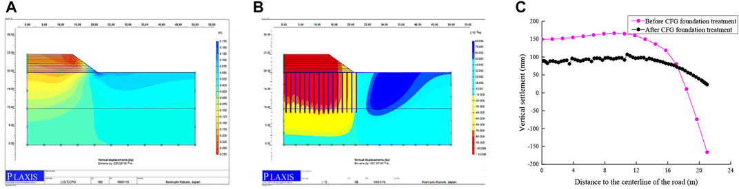
FIGURE 1. Settlement calculation results before and after foundation treatment: (A) Vertical settlement of the road without foundation treatment; (B) Vertical settlement of the road after CFG pile foundation treatment; (C) Distribution of vertical settlement of pile top along the width of the embankment before and after foundation treatment.
As demonstrated in Figure 2. Regarding the horizontal displacement of the roadbed, the embankment load was transferred to the deeper soil layer given the reinforcement of piles. The shallow soil mass exhibited no significant horizontal displacement, while the deep soil mass possessed a certain horizontal displacement (the horizontal displacement is positive toward the center of the embankment). The shallow horizontal displacement decreased from 362.54mm to 151.85mm, transferring the shallow horizontal displacement to the deep layer and guaranteeing the safety of the structure. After CFG pile foundation treatment, the horizontal displacement of the pile top was small and directed towards the center of the embankment.
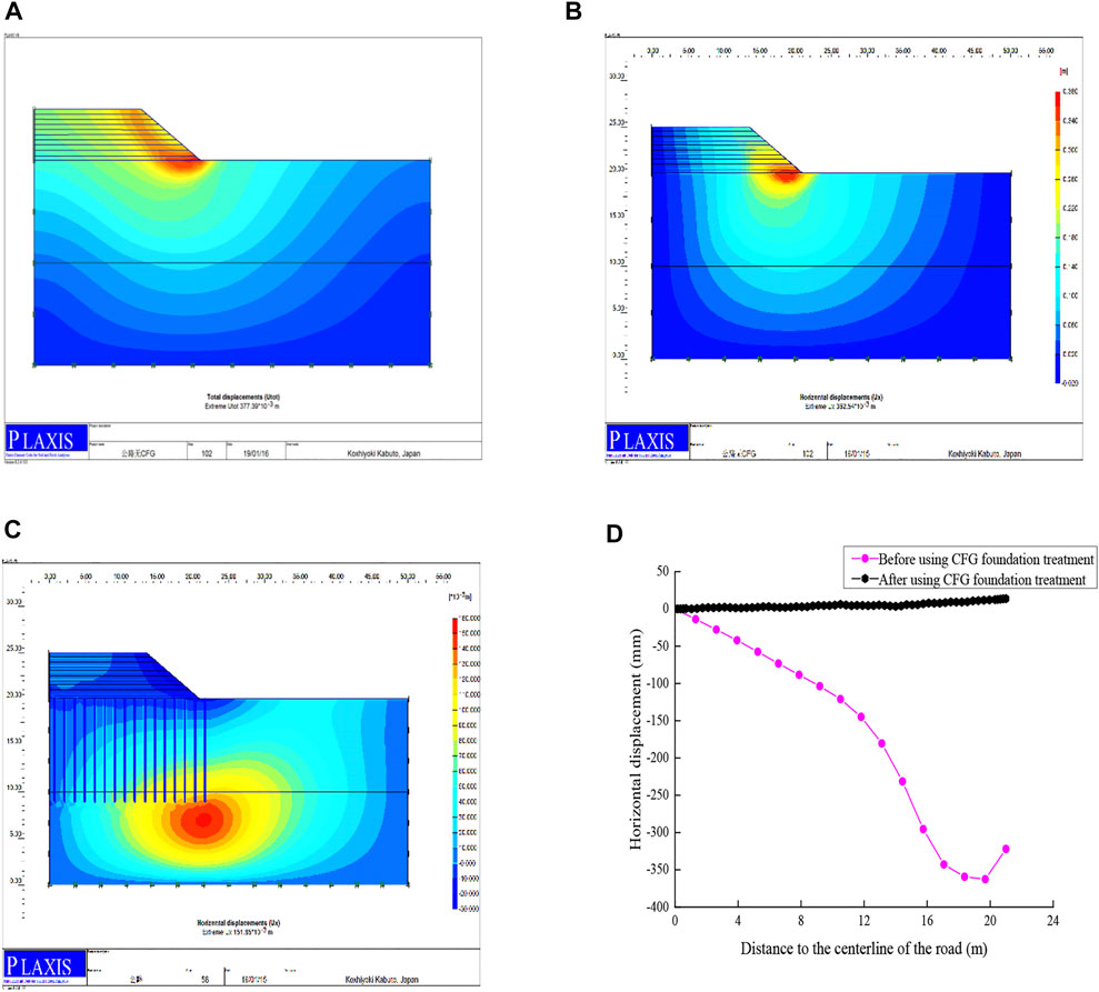
FIGURE 2. Calculation results of horizontal displacement before and after foundation treatment: (A) Deformation form of embankment without foundation treatment; (B) Horizontal displacement of the highway without foundation treatment; (C) Horizontal displacement of the highway after CFG pile foundation treatment; (D) Distribution of horizontal displacement of pile top along the width of the embankment before and after foundation treatment.
Generally, the highway embankment after CFG pile foundation treatment was significantly reinforced and demonstrated significantly improved structural performance compared with the original embankment. To summarize, the following effects can be achieved:
1) The settlement was significantly reduced. The maximum settlement decreased from 253.25mm to 107.23mm, with a decrease of about 57.66%.
2) The uneven settlement effect was significantly improved. At the pile top position, the settlement was evenly distributed along the width of the embankment, and there was no significant change.
3) The horizontal displacement was effectively lowered. Since the embankment load was transferred to the deeper soil layer, the horizontal displacement was transferred from the shallow layer to the deep soil layer, decreasing from 362.54mm to 151.85 mm. As a result, safety was strengthened.
4) The horizontal displacement of the embankment was effectively controlled. Under the action of the pile body, the horizontal displacement of the pile top was controlled to a small value, and the displacement to both sides of the road was avoided.
5 Analysis of factors influencing the reinforcement effect of cement fly-ash gravels pile composite foundation
The CFG pile had a significant reinforcement effect on the highway embankment, while it was affected by multiple factors. Clarifying the influence factors of CFG pile composite foundation treatment was of great significance to explore its reinforcement mechanism. In this study, parameter analysis of pile length and pile distance of the CFG pile composite foundation, as well as the thickness of gravel cushion under the embankment, was performed using the numerical method to understand the main factors and changing laws of the reinforcement effect of the CFG pile composite foundation.
5.1 Influence of pile length on the composite foundation
With pile length as a variable quantity, 11, 13, and 15 m were selected to obtain the changes in the vertical settlement and horizontal displacement of the embankment at the pile top along the embankment width resulting from the change in pile length. Figure 3 suggested that the vertical settlement was significantly affected when the pile length changed from 11m to 15m, and the horizontal displacement was different depending on the pile length. The maximum settlement was 107mm and 41.86 mm when the pile length was 11m and 15m, respectively. The horizontal displacement trend and size distribution were similar when the pile length was 11m and 13 m. The horizontal displacement was significantly controlled when the pile length was 15 m. Therefore, the improvement effect of the CFG pile length on the settlement was significantly stronger than that of horizontal displacement, and the change was more linear with pile length. However, the horizontal displacement was different with different pile lengths. The horizontal displacement was effectively controlled when the pile length exceeded 13 m. The pile length had little effect on the horizontal displacement when it was less than 13 m. Hence, when CFG pile was used for highway soft foundation reinforcement, an appropriate pile length should be considered to ensure that settlement could be controlled, while the influence of pile length can be overlooked for the relatively minor horizontal displacement.
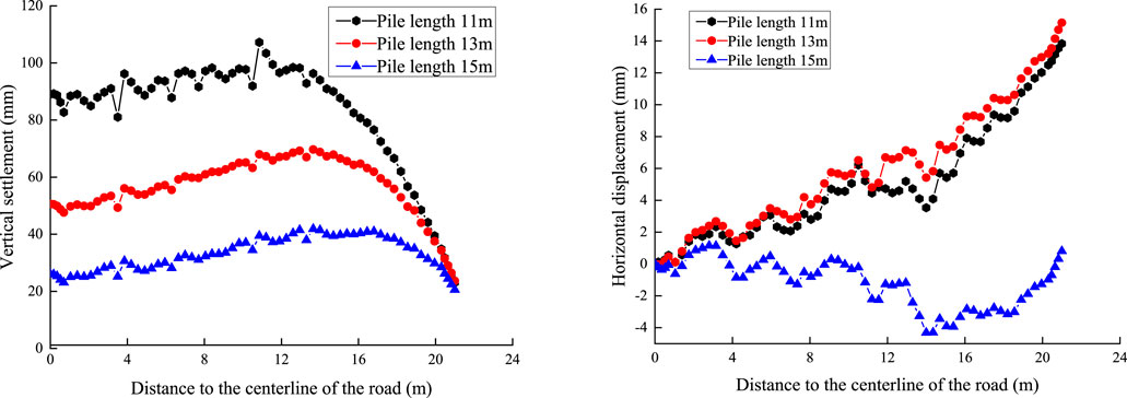
FIGURE 3. Influence of pile length change on reinforcement effect of CFG pile composite foundation:(A) Vertical settlement affected by pile length; (B) horizontal displacement affected by pile length.
Standard working conditions:(1) pile length: 11 m, pile distance: 1.4 m, cushion: 0.4 m; (2) pile length: 13 m, pile distance: 1.4 m, cushion: 0.4 m; (3) pile length: 15 m, pile distance: 1.4 m, cushion: 0.4 m. As shown in Figure 4.
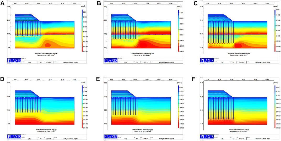
FIGURE 4. Horizontal soil pressure of pile length: (A) 11m; (B) 13m; (C) 15 m. Vertical soil pressure of pile length: (D) 11m; (E) 13m; (F): 15 m
The statistical diagrams of the horizontal and vertical soil pressures of the roadbed under different pile lengths are shown in the figures below:
5.2 Influence of pile distance on composite foundation
With pile distance as the variable quantity, 1.2, 1.4, and 1.6 m were selected to obtain the changes in the vertical settlement and horizontal displacement of the embankment at the pile top along the embankment width owing to the changes in the pile distance. As implied in Figure 5, the changes in the pile distance slightly affected the vertical settlement, because the change of pile distance has little impact on the replacement rate of pile and the vertical elastic modulus of composite foundation, with barely any change in the vertical settlement. But significantly affected the horizontal displacement. As the pile distance changed from 1.2 m to 1.6 m, the vertical settlement distribution and size were almost the same without significant difference, and the pile distance had a limited effect on the vertical settlement change. However, the changes in the pile distance significantly improved the soil stiffness in the horizontal direction. With the decrease in the pile distance, the horizontal stiffness of the soil mass increased, and the horizontal displacement decreased. The maximum horizontal displacement was 22.84mm and 3.85 mm when the pile distance was 1.2 m and 1.6 m, respectively. Therefore, the changes in the pile distance effectively influenced the horizontal displacement change in the design process of the CFG pile.
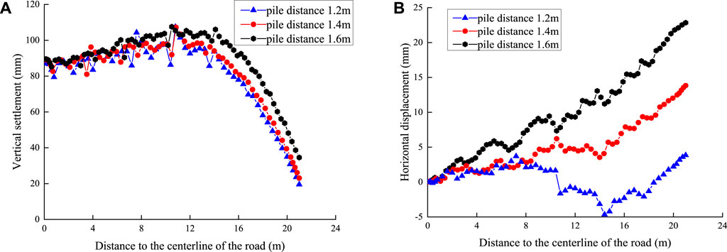
FIGURE 5. Influence of pile distance change on reinforcement effect of CFG pile composite foundation: (A) Vertical settlement affected by pile distance; (B) horizontal displacement affected by pile distance.
Standard working conditions: (1) pile length: 11m, pile distance: 1.2m, cushion: 0.4 m; (2) pile length: 11 m, pile distance: 1.4 m, cushion: 0.4 m; (3) pile length: 11m, pile distance: 1.6 m, cushion: 0.4 m. As shown in Figure 6.
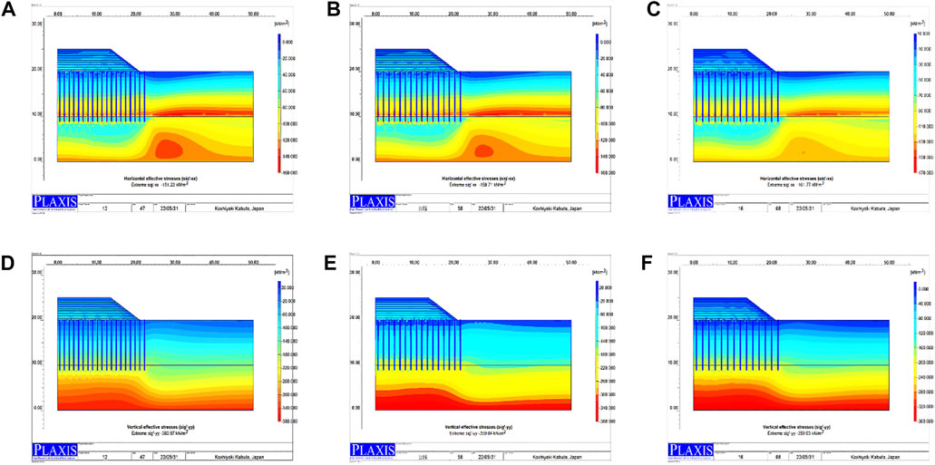
FIGURE 6. Horizontal soil pressure of pile distance: (A) 1.2m; (B) 1.4m; (C) 1.6 m. Vertical soil pressure of pile distance: (D) 1.2m; (E) 1.4m; (F) 1.6 m
The statistical diagrams of the horizontal and vertical soil pressures of the roadbed under different pile distances are shown in the figures below:
5.3 Influence of gravel cushion on composite foundation
With the cushion thickness as the variable quantity, 0.4, 0.6, and 0.8 m were selected to obtain the changes in the vertical settlement and horizontal displacement of the embankment at the pile top induced by the cushion thickness changes along the embankment width. As demonstrated in Figure 7 the gravel cushion exerted no impact on the structural deformation due to the large embankment height and equivalent load. Moreover, the changes in the cushion thickness did not cause significant differences in the structural response.
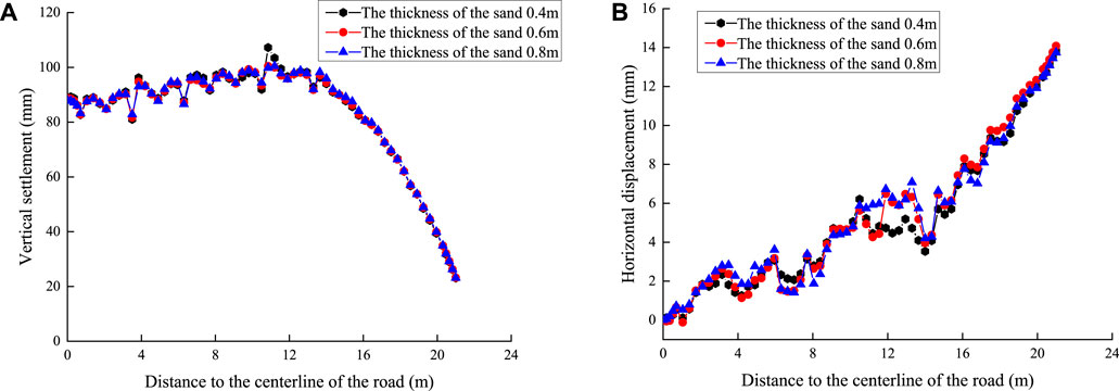
FIGURE 7. Influence of cushion thickness change on reinforcement effect of CFG pile composite foundation: (A) Vertical settlement affected by cushion thickness; (B) horizontal displacement affected by cushion thickness.
Standard working conditions: (1) pile length: 11 m, pile distance: 1.4m, cushion: 0.4m; (2) pile length: 11 m; (3) pile distance: 1.4m, cushion: 0.6 m pile length: 11 m, pile distance: 1.4 m, cushion: 0.8 m. As shown in Figure 8.
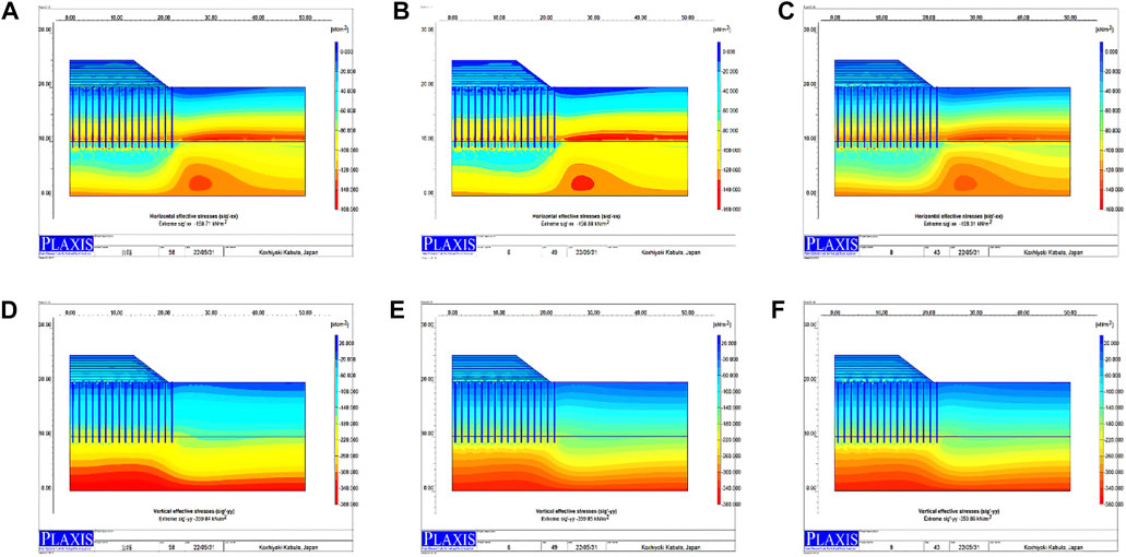
FIGURE 8. Horizontal soil pressure of cushion thickness: (A) 0.4m; (B) 0.6m; (C) 0.8 m. Vertical soil pressure of cushion thickness: (D) 0.4m; (E) 0.6m; (F) 0.8 m
The statistical diagrams of the horizontal and vertical soil pressures of the roadbed under different cushions are shown in the figures below:
The numerical method was used to analyze the pile length, pile distance, and the thickness of the gravel cushion of the CFG pile composite foundation. The changes in the pile length had a significant impact on the vertical settlement of the embankment, and the settlement decreased significantly with the increase in the pile length. The changes in the pile distance had a significant impact on the horizontal displacement of the embankment, and the horizontal displacement of the soil was reduced with the increase in the horizontal stiffness of the pile distance. The influence of cushion thickness on the vertical settlement and horizontal displacement of the embankment was small and can be ignored. In the design process, the pile length is considered with the vertical settlement as the main control variable, the horizontal displacement of the embankment is controlled through appropriate pile distance, and the cushion is not the focus of the structural design.
As revealed by the above analysis, the CFG pile can improve highway soft foundation, reflected in the following aspects. (1) The settlement was significantly reduced; (2) The effect of uneven settlement was significantly improved; (3) the horizontal displacement was effectively reduced; (4) the horizontal displacement of the embankment was controlled. After CFG pile treatment, the service performance of the highway embankment was improved, and its safety and stability were guaranteed.
6 Dynamic response of vehicle load of roadbed
The design concept of current roadbeds in China is based on statics theory, which is slightly different from the actual situation, especially with low embankments. Since vehicle load is a dynamic load, it is insufficient to replace its effect on roadbeds with static force (Song et al., 2021; Milne et al., 2017). Various dynamic loads such as earthquake and vehicle vibration may cause the liquefaction, instability and subsidence of saturated soft soil subgrade. By increasing the external load, the soft foundation can be compressed, which causes lateral and vertical deformation to the soft foundation. If this deformation occurs in the bridge, it can lead to bridge jump, the uneven settlement in the middle of the road, transverse cracking and so on. Therefore, the theory of roadbed design must develop from a static method to a dynamic method. It is of practical significance to explore the dynamic effect of vehicle loads on highway roadbeds (Li and Selig, 1996; Liu et al., 2021).
The 3D finite element method and Midas gts nx were employed to establish the composite foundation model after CFG pile treatment. Then, the dynamic load of the vehicle was utilized to analyze the variation rule of vertical velocity and acceleration of the roadbed. The simulation results are of great significance to the development of foundation treatment technology for soft soil roadbed engineering.
This model simulated a vehicle fleet with a speed of 40km/h on the road. It was assumed that moving vehicles passed each node of the model in a short time, the impact load was applied to the node, and the impact load was idealized into a triangle. The simulation of automobile load adopted the built-in train load function, with wheelbase and axle weight parameters being modified. The axle weight and axle base parameters were set according to The General Code for Highway Bridge and Culvert Design (JTG D60-2015). Among them, the duration of applying train dynamic loading was 3s, and the time increment was 0.03s.
Representative nodes and model cross-sections were selected to analyze the dynamic characteristics of the roadbed. Three nodes were selected as the research working condition points at the starting point, midpoint, and end point of the central axis of the roadbed surface.
The following assumptions will be made during the simulation. (1) All materials in the model are homogeneous, continuous and isotropic. (2) The Mohr coulomb yield condition is used to simulate each soil layer. CFG pile is simulated by beam element. (3) Ignoring the relative slip between CFG pile and soil, composite foundation is used for simulation. (4) Considering the mutual space effect, a THREE-DIMENSIONAL model is used for numerical simulation. The model is exhibited in Figure 9.
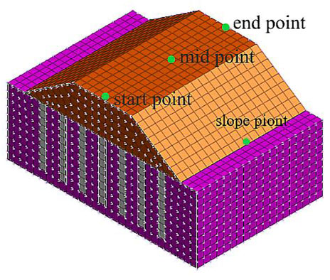
FIGURE 9. CFG pile composite foundation model.
6.1 Distribution rule of the vertical velocity of road surface along the longitudinal roadbed surface
With time as the abscissa and vertical velocity response value as the ordinate, the simulation results were drawn into the variation curve of the vertical velocity of the roadbed surface. As implied by the vibration velocity in Figure 10, the vibration of each point in the roadbed had a certain response time with the movement of the train. The variation of the vertical velocity of each part of the roadbed surface exhibited regular vibration.
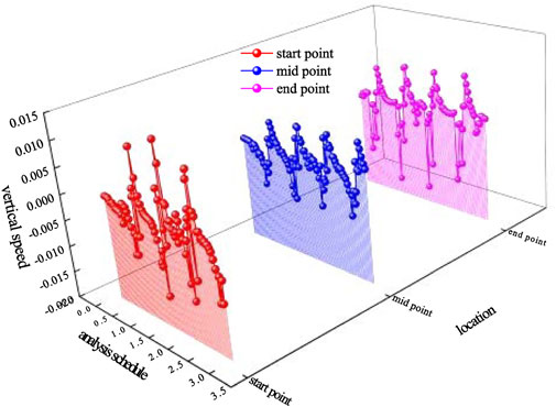
FIGURE 10. Vibration rule of the vertical velocity along with different road surface feature points in driving direction.
At the starting point of the road surface, the positive and negative maximum values of the vertical vibration velocity were 0.01427 m/s and -0.01397m/s, respectively, with relatively close absolute values. At the midpoint of the road surface, the positive and negative maximum values of the vertical vibration velocity were 0.00617 m/s and -0.00877 m/s, respectively, with an absolute value difference of about 30%. At the endpoint of the road surface, the positive and negative maximum values of the vertical vibration velocity are 0.00832m/s and -0.01681 m/s, respectively, presenting an absolute value difference of around 50%.
According to the time travel curves of each feature point, the vibration law of each feature point is the same, demonstrating a periodic motion with different peak values and periods.
6.2 Distribution rule of the vertical velocity of roadbed points at different depths on the cross-section of roadbed midpoint
With time as the abscissa and vertical velocity response value as the ordinate, the simulation results were drawn into the variation curve of the vertical velocity of the roadbed surface. As unveiled from the vibration velocity in Figure 11, the variation of the vertical velocity of each part of the roadbed surface exhibited regular vibration with the movement of the train.
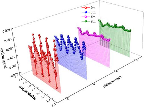
FIGURE 11. Vibration rule of the vertical velocity of feature points at different depths of midpoint cross-section of the roadbed.
It can be observed that at the midpoint of the roadbed, the positive and negative maximum values of the vertical vibration velocity were 0.00622m/s and -0.00886m/s, respectively, with an absolute value difference of about 30%. The positive and negative maximum values of the vertical vibration velocity were 0.00257m/s and -0.00408m/s, respectively, at 3 m below the midpoint of the roadbed, and the absolute value difference was around 50%. At 6 m below the road surface at the midpoint of the roadbed, the positive and negative maximum values of the vertical vibration velocity were 0.000606m/s and -0.00199m/s, respectively, displaying an absolute value difference of approximately 70%. At 9 m under the road surface at the midpoint of the roadbed, the positive and negative maximum values of the vertical vibration velocity were 0.000605m/s and -0.00199m/s, respectively, demonstrating an absolute value difference of roughly 70%.
As the depth increased, the peak value of the vertical vibration velocity at the feature point gradually decreased, the additional stress in the subgrade gradually decreases to zero, and the vertical vibration velocity at 6m and 9 m below the road surface was the same. Therefore, as the depth increases, the additional stress generated by dynamic load in the soil layer declines continuously, and the vibration generated by vehicle driving has diminishing influence on the roadbed. When it is below 6m, the additional stress becomes extremely low, its effect is almost uniform, and its absolute value is negligible.
The time travel curves of each feature point uncovered that the vibration laws of each feature point were the same. In other words, they presented a periodic motion with different peak values. With the increase in the depth of feature points, the vibration peak decreased gradually, while the period was the same.
6.3 Distribution rule of vertical acceleration of roadbed surface along the longitudinal road surface
With time as the abscissa and vertical velocity response value as the ordinate, the simulation results were drawn into the variation curve of the vertical acceleration of the roadbed surface. The vibration acceleration in Figure 12 suggested that the vibration of the roadbed exhibited a certain response time with the movement of the train. Meanwhile, the variation of the vertical velocity of each part of the roadbed surface changed regularly.
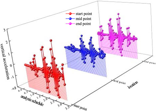
FIGURE 12. Vibration rules of vertical acceleration of feature points along different road surfaces in driving directions.
At the midpoint of the roadbed, the positive and negative maximum values of the vertical vibration acceleration were 2.511m/s−2 and -1.949m/s−2, respectively, and the absolute value difference was about 22%. At the midpoint of the roadbed, the positive and negative maximum values of the vertical vibration acceleration were 1.3471m/s−2 and -1.2708m/s−2, respectively, with an absolute value difference of roughly 6%. At the endpoint of the roadbed, the maximum positive and negative values of the vertical vibration acceleration were 2.1971m/s−2 and -1.9319m/s−2, respectively, demonstrating an absolute value difference of around 12%.
According to the time travel curves of each feature point, the vibration law of each feature point was the same, showing a periodic motion with different peak values and periods. Moreover, the time point of peak acceleration at each point was delayed owing to the difference in the arrival time of vehicle loads. The peak value of acceleration at the starting point was relatively close to that at the endpoint, while the acceleration value at the midpoint of the roadbed remarkably differed from the first two because the first two were at the model boundary and affected by the boundary constraints.
6.4 Distribution rules of vertical acceleration of roadbed points at different depths on the cross-section of roadbed midpoint
With time as the abscissa and vertical acceleration response value as the ordinate, the simulation results were drawn into the variation curve of the vertical acceleration of the roadbed surface. The vibration speed in Figure 13 revealed that the variation of the vertical acceleration of each part of the roadbed surface changed regularly with the movement of the train.
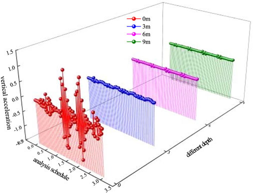
FIGURE 13. Vibration rules of vertical acceleration of feature points at different depths of the cross-section of roadbed midpoint.
At the midpoint of the roadbed, the positive and negative maximum values of the vertical vibration acceleration were 1.3471m/s and -1.2708m/s, respectively, and the absolute value difference was about 6%. The positive and negative maximum values of the vertical vibration velocity were 0.07482m/s and -0.0583m/s, respectively, at 3 m below the midpoint of the roadbed, with an absolute value difference of roughly 22%. At 6 m below the road surface at the midpoint of the roadbed, the positive and negative maximum values of the vertical vibration acceleration were 0.03922m/s and -0.04671m/s, respectively, presenting an absolute value difference of approximately 19%. At 9 m under the road surface at the midpoint of the roadbed, the positive and negative maximum values of the vertical vibration acceleration were 0.03926m/s and -0.04674m/s, respectively, and the absolute value difference was around 19%.
On the road surface, the vertical vibration acceleration of the feature point was the largest. The peak value of the vertical vibration acceleration of the feature point sharply decreased to about 1/20 of that of the road surface feature point when the depth increased by 3 m. The maximum positive vertical vibration acceleration at 6 m below the road surface was reduced to about 1/2 of that at 3 m below the road surface. The vertical vibration acceleration at 6m and 9 m below the road surface was the same. Therefore, the acceleration transfer depth of roadbed vibration caused by the vibration of vehicle driving was relatively small, which mainly affected the road surface and the range of about 4 m under the road surface. Additionally, the influence was almost the same from 6 m below the depth, and its absolute value can be overlooked.
6.5 Distribution rule of vertical vibration acceleration of roadbed slope point
With time as the abscissa and vertical acceleration response value as the ordinate, the simulation results were drawn into the variation curve of the vertical acceleration of the roadbed slope point. As suggested by the vibration acceleration in Figure 14, the vertical vibration of slope points presented certain rules with the movement of trains. The positive and negative maximum values of the vertical vibration acceleration were 0.002314m/s and -0.00265m/s, respectively, with an absolute value difference of about 14%.
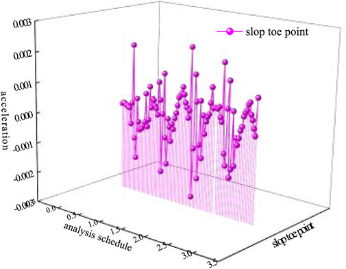
FIGURE 14. Vibration rule of vertical acceleration of roadbed slope point at midpoint.
The time interval between the peak accelerations was about 0.69s. If it was calculated according to the set vehicle speed, the driving distance was exactly the distance between the front and rear axles of a standard vehicle. The roadbed slope point demonstrated irregular vibrations when the vehicle distance was irregular.
7 Conclusion
1) The settlement was significantly reduced; The effect of uneven settlement was significantly improved; the horizontal displacement was effectively reduced; the horizontal displacement of the embankment was controlled. After CFG pile treatment, the service performance of the highway embankment was improved, and its safety and stability were guaranteed.
2) The vertical velocity and acceleration of the roadbed were significantly reduced after the roadbed section was strengthened by the CFG pile. The dynamic issue induced by roadbed moving with trains’ dynamic load was improved to effectively ensure the normal and safe operation of the road.
3) Under the action of the dynamic load of vehicles, the vertical velocity and acceleration of the roadbed decreased slightly within 0.3 m below the roadbed surface, and the attenuation speed was relatively fast within 0.3–3 m. The values of the two were very small, basically close to 0, when it was below 3 m. This suggested that the influence range of vehicle dynamic load was mainly concentrated in the roadbed surface below 3 m. Therefore, this point should be fully considered in the design, construction, and reinforcement of engineering.
4) After the CFG pile reinforcement, the stress of the upper layers of soil mass and roadbed was effectively improved. In addition to guaranteeing the roadbed settlement, the foundation reinforced by the pile also bore the downward load of moving vehicles to a great extent, contributing to bettering the working properties of the roadbed and prolonging its service life (Bai et al., 2021b).
Data availability statement
The original contributions presented in the study are included in the article/supplementary material, further inquiries can be directed to the corresponding author.
Author contributions
HZ is responsible for referencewriting and calculation LL is responsible for establishing finite elementmodel WF is responsible for making pictures and tables YZ is responsible for collecting site data WZ is responsible for model building and data analysis BZ is responsible for collecting site samples and conceiving the framework of the paper.
Funding
This research was funded by the Hubei Provincial Engineering Research Center of Slope Habitat Construction Technique Using Cement-based Materials (China Three Gorges University) Open Research Program (2022SNJ07、2022SNJ04), and the Nei Monggol Autonomous Region Science and Technology Major Project (2021ZD0007-03).
Conflict of interest
The authors declare that the research was conducted in the absence of any commercial or financial relationships that could be construed as a potential conflict of interest.
Publisher’s note
All claims expressed in this article are solely those of the authors and do not necessarily represent those of their affiliated organizations, or those of the publisher, the editors and the reviewers. Any product that may be evaluated in this article, or claim that may be made by its manufacturer, is not guaranteed or endorsed by the publisher.
References
Alamgir, M., Miura, N., Poorooshasb, H. B., and Madhav, M. (1996). Deformation analysis of soft ground reinforced by columnar inclusions. Comput. Geotechnics 18 (4), 267–290. doi:10.1016/0266-352x(95)00034-8
Bai, B., Yang, G., Li, L., and Yang, G. (2019). A thermodynamic constitutive model with temperature effect based on particle rearrangement for geomaterials. Mech. Mater. 139, 103180. doi:10.1016/j.mechmat.2019.103180
Bai, B., Xu, T., Nie, Q., and Li, P. (2020). Temperature-driven migration of heavy metal Pb2+ along with moisture movement in unsaturated soils. Int. J. Heat Mass Transf. 153, 119573. doi:10.1016/j.ijheatmasstransfer.2020.119573
Bai, B., Zhou, R., Cai, G., Hu, W., and Yang, G. (2021a). Coupled thermo-hydro-mechanical mechanism in view of the soil particle rearrangement of granular thermodynamics. Comput. Geotechnics 137 (8), 104272. doi:10.1016/j.compgeo.2021.104272
Bai, B., Nie, Q., Zhang, Y., Wang, X., and Hu, W. (2021b). Cotransport of heavy metals and SiO2 particles at different temperatures by seepage. J. Hydrology 597, 125771. doi:10.1016/j.jhydrol.2020.125771
Bai, B., Wang, Y., Rao, D., and Bai, B. (2022). The effective thermal conductivity of unsaturated porous media deduced by pore-scale SPH simulation. Front. Earth Sci. 10, 943853. doi:10.3389/feart.2022.943853
Liu, B., Lin, J., Ku, X., et al. (2021). Particle migration induced by hydrodynamic interparticle interaction in the Poiseuillel fow of a Giesekuslfuid[J]. J. Brazilian Soc. Mech. Sci. Engg. 43 (2), 2852–2856.
Cheng, X. S., Jing, W., Yin, C., and Li, C. (2018). Stability parameter analysis of a composite foundation of an oil storage tank in a loess area treated with compaction piles[J]. Soils Found. 58, 306. doi:10.1016/j.sandf.2018.02.004
Peng, Y. Z., Bing, B., and Si, C. J. (2016). Coupled effects of hydrodynamicforces and pore structure on suspended particle transport and deposition in a saturated porous medium[J]. Rock and Soil Mechanics 37 (5), 1307–1316.
Cui, X., Fan, Y., Wang, H., and Huang, S. (2019). Experimental investigation of suspended particles transport in porous medium under variable temperatures. Hydrol. Process. 33 (7), 1117–1126. doi:10.1002/hyp.13390
Cui, X., Wu, D., Wang, H., Ding, S., and Fan, Y. (2022). Pore features and seepage characteristics of natural gap-graded sand with two size distributions. Géotechnique, 1–12. doi:10.1680/jgeot.21.00213
Derbyshire, E., Dijkstra, T. A., Smalley, I. J., and Li, Y. (1994). Failure mechanisms in loess and the effects of moisture content changes on remoulded strength. Quat. Int. 24 (24), 5–15. doi:10.1016/1040-6182(94)90032-9
Habibagahi, G., and Mokhberi, M. (1998). A hyperbolic model for volume change behavior of collapsible soils. Can. Geotech. J. 35 (2), 264–272. doi:10.1139/t97-089
Jones Jr, J. S. (1981). State-of-the-art report — Engineering practice in artificial ground freezing[J]. Eng. Geol. 18 (1-4), 313–326. doi:10.1016/B978-0-444-42010-7.50034-7
Jung, J. B., Lee, K. I., Lee, J. S., and Chang, Y. C. (2001). Numerical analyses of composite ground improved by fully and partly penetrated sand compaction piles. KSCE J. Civ. Eng. 5 (2), 165–173. doi:10.1007/bf02829072
Lai, J., Liu, H., Qiu, J., and Chen, J. (2016). Settlement analysis of saturated tailings dam treated by CFG pile composite foundation. Adv. Mater. Sci. Eng. 2016 (6), 1–10. doi:10.1155/2016/7383762
Li, D., and Selig, E. T. (1996). Cumulative plastic deformation for fine-grained subgrade soils. J. Geotech. Engrg. 122 (12), 1006–1013. doi:10.1061/(asce)0733-9410(1996)122:12(1006)
Milne, D. R. M., Le Pen, L. M. L., Thompson, D. J., and Powrie, W. (2017). Properties of train load frequencies and their applications. J. Sound Vib. 397, 123–140. doi:10.1016/j.jsv.2017.03.006
Otani, J., Ochiai, H., and Yamamoto, K. (1998). Bearing capacity analysis of reinforced foundations on cohesive soil. Geotext. Geomembranes 16 (4), 195–206. doi:10.1016/s0266-1144(98)00005-3
Tan, S. (1995). Validation of hyperbolic method for settlement in clays with vertical drains.[J]. Soils Found. 35 (31), 125–131. doi:10.3208/sandf1972.35.101
Song, W., Liu, X., Zheng, C., et al. (2021). Migration-deposition characteristics of exogenous particles near the injection well in a groundwater heat pump system[J]. Geothermics 94 (1), 102097.
Ye, S. H., and Gong, X. N. (2017). “Static load test of a project CFG pile composite foundation[C],” in International conference on mechanics and architectural design, 175–180.
Keywords: soft foundation treatment, CFG, foundation settlement, dynamic load, dynamic response
Citation: Zhang H, Liu L, Feng W, Zhou Y, Zheng W and Zhao B (2022) Design selection and dynamic response analysis of CFG pile composite foundation in soft soil areas. Front. Mater. 9:980375. doi: 10.3389/fmats.2022.980375
Received: 28 June 2022; Accepted: 11 July 2022;
Published: 05 August 2022.
Edited by:
Bing Bai, Beijing Jiaotong University, ChinaReviewed by:
Yongchao Tian, Henan Polytechnic University, ChinaHe Liu, University of South China, China
Copyright © 2022 Zhang, Liu, Feng, Zhou, Zheng and Zhao. This is an open-access article distributed under the terms of the Creative Commons Attribution License (CC BY). The use, distribution or reproduction in other forums is permitted, provided the original author(s) and the copyright owner(s) are credited and that the original publication in this journal is cited, in accordance with accepted academic practice. No use, distribution or reproduction is permitted which does not comply with these terms.
*Correspondence: Bingqin Zhao, bingqinzhao@163.com