Improving the anti-thermal-shock properties of Sc2O3-Y2O3-ZrO2-CaF2-PHB abradable coatings by fabricating the textures on ceramic matrix composites: experiment verification and numerical analysis
 Jian-nong Jing
 Le Zhang1,2
 - 1Science and Technology on Power Beam Processes Laboratory, AVIC Manufacturing Technology Institute, Beijing, China
- 2Aviation Key Laboratory of Science and Technology on Advanced Surface Engineering, AVIC Manufacturing Technology Institute, Beijing, China
- 3National Key Laboratory for Remanufacturing, Army Academy of Armored Forces, Beijing, China
- 4College of Mechanical Engineering, Zhejiang University of Technology, Hangzhou, China
The abradable coating is one of the most important coatings for improving the efficiency of aeroengine. To improve the durability of Sc2O3-Y2O3-ZrO2-CaF2-PHB abradable coating under the conditions of high temperature thermal shock, the femtosecond laser processing technology is proposed to fabricate the texture on the surface of SiCf/SiC composites to improve the coating/matrix contact area. The environmental barrier coating (EBC) was prepared by vacuum plasma spraying (VPS) equipment on SiCf/SiC ceramic matrix composites to avoid water-oxygen corrosion. And the abradable coating was prepared by air plasma spraying (APS) equipment on the EBC. The thermal shock test of the abradable coating at (1,250 ± 50)°C was established in the simulated gas environment of the oxygen-propane flame, and the variation of interface stress between the layers during the thermal shock test was analyzed by ANSYS software. The hidden crack between the layers was detected by an infrared thermal imager. The results show that the surface textures have significant influences on the anti-thermal-shock properties of Sc2O3-Y2O3-ZrO2-CaF2-PHB abradable coating by improving the contact area and optimizing the interface stress distribution. The bonding strengths of the coating are increased by 14.6% and 42.2% when the surface textures increase the contact area of the substrate and the coating by 41.3% and 104%, respectively. Compared with the coatings without texture treatments, the coatings with texture treatments can reduce coating thickness by 30% and the coatings do not peel off after the thermal shock tests. Influenced by the cyclic thermal stress, the cracks of abradable coating are initiated at the defect position and gradually propagated a shell-like shape. The textures on the surface of SiCf/SiC composites have deep influences on improving the high-temperature thermal shock life of Sc2O3-Y2O3-ZrO2-CaF2-PHB abradable coating.
1 Introduction
In recent years, SiCf/SiC ceramic matrix composites were rapidly developed in the field of are-engine owing to their properties, such as low density, high specific strength, high temperature resistance, oxidation resistance, ablation resistance, etc. (Eaton and Linsey, 2002; Kathavate et al., 2019; Du et al., 2022; Hu et al., 2022; Huang et al., 2023). SiCf/SiC ceramic matrix composites have become potential materials which can be used for fabricating combustion chamber, turbine blades, turbine guide vanes, turbine outer ring, etc. (Piollet et al., 2019). However, the mechanical properties of SiCf/SiC ceramic matrix composites are decreased sharply in the environment of high-temperature and humid. A multilayer EBC coating is necessary to protect the SiCf/SiC ceramic matrix composites from water-oxygen corrosion (Cheng et al., 2019; Arnal et al., 2022).
As an essential part of are-engine, the turbine outer ring plays a role in separating the air flow from the compressor and gas turbine and directing the air flow to the next level. The abradable coating on the surface of turbine outer ring which is allowed to be scraped by the turbine blade tips is the key technology of improving the thrust-to-weight ratio of aero-engine. Generally, the abradable coating should be easily rubbed off to have well sealing performance. However, for the turbine outer ring which made by SiCf/SiC ceramic matrix composites, the EBC coating cannot be used for sealing because of its high hardness and low porosity. The optimal method is preparing the abradable coating on the EBC coating. The characteristics of large thickness, multilayer structure and low stress tolerance of the coating system (EBC + abradable coating) can easily cause the abradable coating to break off in the harsh environment of high temperature scouring, which would pose a great safety risk to the engine. The greatest challenge of the coating system is to acquire high bonding strength (Hardwicke and Lau, 2013; Delebarre et al., 2017; Zhang and Marshall, 2018; Ziegelheim et al., 2019).
To solve the problem that the coatings are easy to damage during the service, many scholars have carried out extensive research by preparing textures on substrates. A. Lamraoui was the first to find that texture diameter and depth would affect the bonding strength (Lamraoui et al., 2010). Kromer found that the bonding strength of coating was affected by the filling rate of spray droplets in the microstructure pits and proved that the droplet diffusion and particle wettability were affected by the microstructure pattern (Reza et al., 2016a). Reza et al. found that microstructure with a certain area occupancy could not only improve the bonding strength of the coating but also release the residual stress inside of the coating (Reza et al., 2016a).
At present, there are still some problems, such as low bonding strength and poor heat shock resistance of the abradable coating of SiCf/SiC composite (Bassaki et al., 2015; Jalalian et al., 2019; Kathavate et al., 2020). Therefore, improving the abradable coating properties is a prerequisite for engineering applications of SiCf/SiC composites. Infinite morphological and geometrical parameter variations give texture a wide development space and application prospects. In this paper, femtosecond laser processing is used to prepare high-wetness textures on the surface of SiCf/SiC composites, and VPS and APS systems are used to prepare EBC coatings and abradable coatings, respectively. The effect of the surface texture on the thermal shock resistance of the coatings has been investigated using simulated gas environment tests, and the effect of the gas environment on the microstructure and structure of the coatings has been discussed using SEM, EDS, XRD, etc. This study has important implications for promoting the application of SiCf/SiC composites, EBC, and their abradable coatings in aeroengine.
2 Experimental methods
2.1 Texture preparation and characterization
SiCf/SiC composites were prepared by precursor impregnation and pyrolysis (PIP) and the sample size was φ25 mm × 5.5 mm. The femtosecond laser (Pharos-20) was used to fabricate the textures on the surface of SiCf/SiC composites under the processing parameters listed in Table 1. The deepness and width of the textures can be controlled by the route planning of the laser beam. To facilitate the analysis of the effect of the contact area on the bonding strength of the coating, the groove structures (Figure 1) with different geometric parameters (Table 2) were chosen as texture. The 0# sample is the contrast without surface treatment by the laser beam.
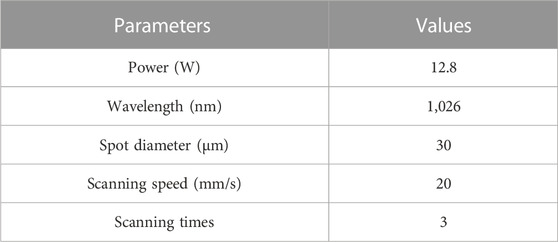
TABLE 1. Processing parameters of the femtosecond laser (Pharos-20).
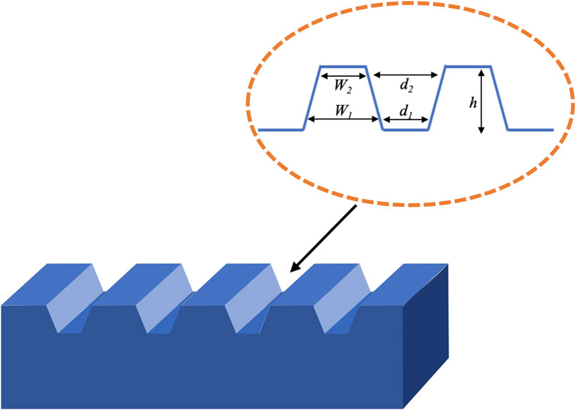
FIGURE 1. Sketch map of groove structure.
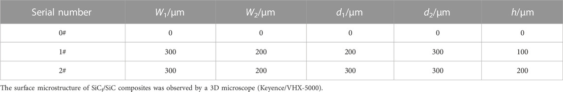
TABLE 2. The geometric parameters of texture.
2.2 Coating preparation and characterization
The EBC coating containing Si-5% Yb2O3 and Yb2Si2O7 layers was prepared by VPS (ZDP-1700). Sc2O3-Y2O3-ZrO2-CaF2-PHB abradable coating was prepared by APS (APS-3000), in which the lubrication phase was CaF2, and the pore forming phase was polybenzoate (PHB). The spraying parameters for EBC and abradable coating are shown in Table 3. After spraying, the PHB was completely removed by holding heat in Muffle-furnace at 500°C for 8 h.
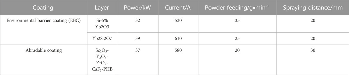
TABLE 3. Spraying parameters of EBC and abradable coating.
Metallographic observation and Elemental analysis were performed by SEM and EDS (Zeiss Supra 55 Sapphire), respectively. Phase identification was tested by XRD (Bruker D8) with a Cu target. The angle scanning range was 20°–90°, and the scanning step was 10°/min. The porosity of the abradable coating was measured by an optical microscope (Leica DMI5000M). The bonding strength of the coating was measured by an electronic universal testing machine. There are 5 samples in each group and the mean value is taken as the test value.
2.3 Thermal shock test
Thermal shock testing was performed by aeroengine thermodynamic extreme environment system. The fuel used for the system was a mixture of propane and oxygen. The maximum temperature was set as (1,250 ± 50)°C and the holding time was set as 2 s. One cycle lasts about 40 s, and the system can record cycles. The diagram of thermal shock test is shown in Figure 2. In each group, 2 parallel samples are used to observe the dissociation phenomena of the coating.
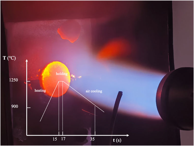
FIGURE 2. Diagram of thermal shock test.
2.4 Interface crack detection
The infrared camera (Avio NEC-R300S) was used to detect interface cracks during the thermal shock process. The detective principle is that cracks in the coatings can prevent the heat flow from diffusing outward. Heat accumulates in the crack zone under laser excitation and the crack zone temperature increases, which is different from the normal zone temperature. The detection parameters of the infrared system are shown in Table 4. The Infrared Professional software was used to extract the temperature value for each pixel in the acquired image, and the two images with the largest temperature difference were selected to be subtracted based on the pixel position.
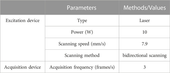
TABLE 4. Detective parameters of infrared system.
3 Analysis of thermal shock model
Stress is an important parameter that can reflect the state of the coating. The stress of the coating will change significantly during the thermal shock experiment. In this paper, ANSYS software is used to explore stress redistribution behavior of coatings. The sine curve is used to describe interface differences, and wavelength (L) and amplitude (A) are used to show interface characteristics. Based on the geometric parameters of texture, the sine curves of three types of coatings are shown in Eqs. 1–3, respectively.
Unit PLANE183, which can be used as a plane unit and an axisymmetric unit, is selected for structural stress analysis. At the same time, this unit has plasticity, creep, large deformation and large strain functions. To ensure the accuracy of the calculation results, a dense mesh (mesh size 1.0 μm) is designed in the regions near the interfaces of the layers. While the other regions are relatively sparse to improve computing efficiency. The stress model and the mesh partitioning diagram are shown in Figure 3. The thermodynamic parameters of the coating and substrate are shown in Table 5.
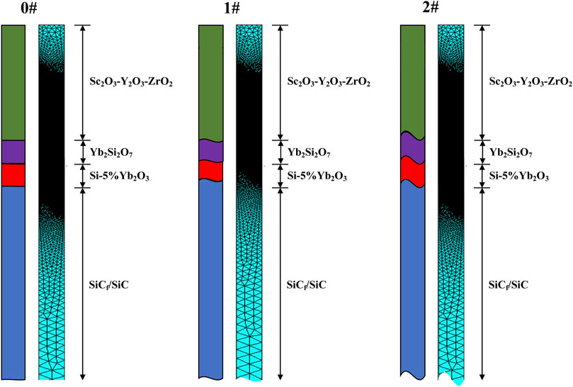
FIGURE 3. Diagram of stress model and mesh division.
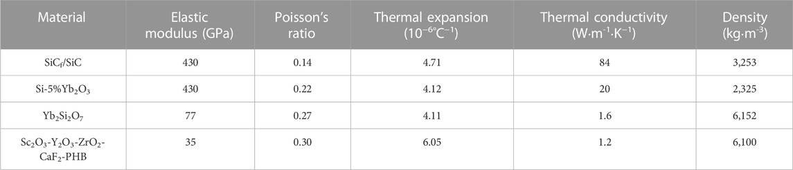
TABLE 5. Thermodynamic parameters of coating.
4 Constraint condition
In the simulation, the thermal conduction behavior in the coating is assumed to be non-unidirectional and the coating has a continuous mechanical behavior. The left boundary of the model uses the symmetry constraint, while the right boundary uses the coupling constraint. Namely, the right boundary can move freely in all directions, but should be simultaneous.
5 Temperature field application
Radiation and convection are the main means of heating and cooling. In general, convection plays a major role when the surface temperature of the coating is low, while radiative effects are gradually enhanced when the surface temperature is raised. In order to investigate the distribution and variability properties of the coating stress field during heating, it is necessary to consider the thermal radiation and thermal convection behavior of both the abradable coating and the substrate backing.
As for radiation, according to Stephan-Boltzmann law, the radiantion of heat flux (qr) under the condition of flame heating can be expressed as:
where
Equation 4 can be dealt with the linear approximation method:
where ar is the heat transfer radiative coefficient, and can be obtained by Eqs. 4, 5:
Table 6 shows the thermal radiation coefficients of Sc2O3-Y2O3-ZrO2-CaF2-PHB abradable coating and SiCf/SiC composites, which means that the Sc2O3-Y2O3-ZrO2-CaF2-PHB abradable coating is heated and the SiCf/SiC composites are cooled by the radiative coefficients. Considering the high surface roughness of the abradable coating and the enclosed combustion environment, the thermal absorptivity of the abradable coating, the thermal emissivity of the flame, and the thermal emissivity of SiCf/SiC in the simulation are set to 1.0, 1.0 and 0.9, respectively.
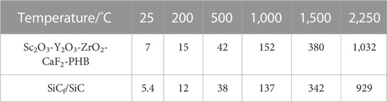
TABLE 6. Thermal radiation coefficients (J·m-2·s-1·K−1).
As for convection, according to Newton’s law of cooling, the convection can be expressed as:
where h is the heat transfer convection coefficient, which depends on pressure, temperature, and flow rate. T is the flame temperature, and T0 is the abradable coating temperature. Table 7 indicates the heat transfer coefficients of Sc2O3-Y2O3-ZrO2-CaF2-PHB abradable coating at different temperatures.where
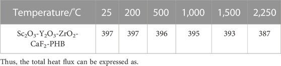
TABLE 7. Heat transfer convection coefficient (J·m-2·s-1·K−1).
To simplify the model, the total heat transfer coefficient is used in the calculations. The surface temperature of abradable coating is 1,250 °C and the environmental temperature is 25°C. The heating time is set to 15 s and the cooling time is set to 20 s. Namely, the flame heats the coating by radiation and convection, and the environment cools the substrate by radiation and convection during the heating process as well.
6 Results and discussion
6.1 Surface texture characterization of SiCf/SiC composites
Figure 4 shows a comparison of the surface morphology of SiCf/SiC composites with three types of process conditions. The surface of the 0# sample is relatively undulating, indicating the original braid treatment. While the surfaces of 1# and 2# samples are arranged neatly with regular shapes. The groove size (Figure 4B, C) can be controlled by femtosecond laser processing. The error between the actual size and the designed size is ± 10 µm. Smaller-sized secondary microstructures are distributed among the primary microstructures, which increases the surface roughness of the composite. The primary microstructure and the secondary microstructure together constitute the micro/nano structure.
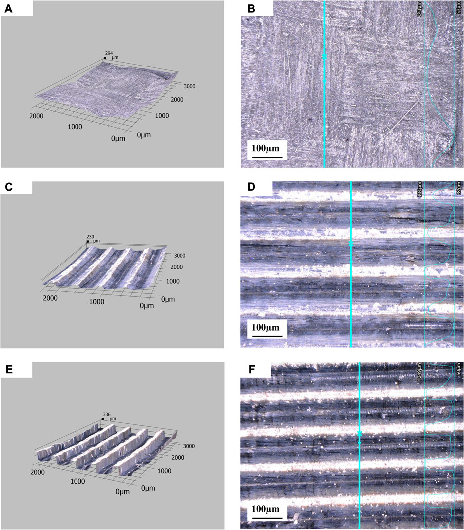
FIGURE 4. Surface morphologies of SiCf/SiC composites (A, B): 0# sample; (C, D): 1# sample; (E, F) 2# sample.
6.2 Characterization of coating
The 1# coating is described in this section, considering that the coating preparation process is the same for all three types of samples. The microstructure of the 1# coating is shown in Figure 5. The coating has three layers, in which the Si-5%Yb2O3 layer and the Yb2Si2O7 layer form the EBC system to protect the SiCf/SiC composite from water-oxygen corrosion, and the outermost layer is the abradable coating to provide the high-temperature sealing function between the motor and the stator. The internal microstructure of the EBC is homogeneous and dense, where the Si-5%Yb2O3 layer fills the grooves and binds well to the matrix interface without apparent defects. While the internal microstructure of Sc2O3-Y2O3-ZrO2-CaF2-PHB abradable coating is uniform and loose, which has a good interface with the EBC. The porosity of the abradable coating is calculated to be 35%.
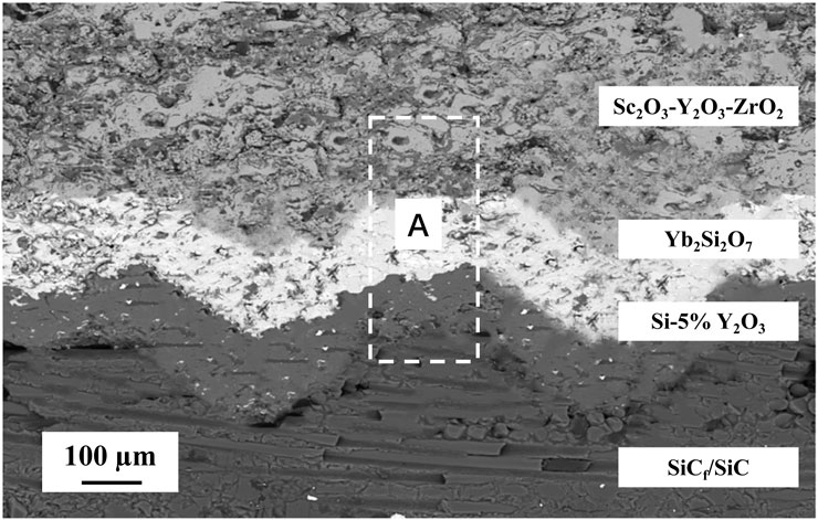
FIGURE 5. Microstructure of the 1# coating.
Figure 6 shows the element distribution results of different layers in Region A (Figure 5) The main element of Si-5%Yb2O3 layer is Si which can reach 96.87%, and O element content in only 2.57%. The main elements Yb2Si2O7 layer are Yb, Si and O, and their contents are 48.27%, 27.08% and 24.68%, respectively. The results indicate that VPS can effectively avoid powder oxidation and obtain high quality EBC. While for the abradable coating, the main elements are Zr, O, Y and Sc which can reach 53.58%, 2.57%, 2.36% and 3.69%, respective.
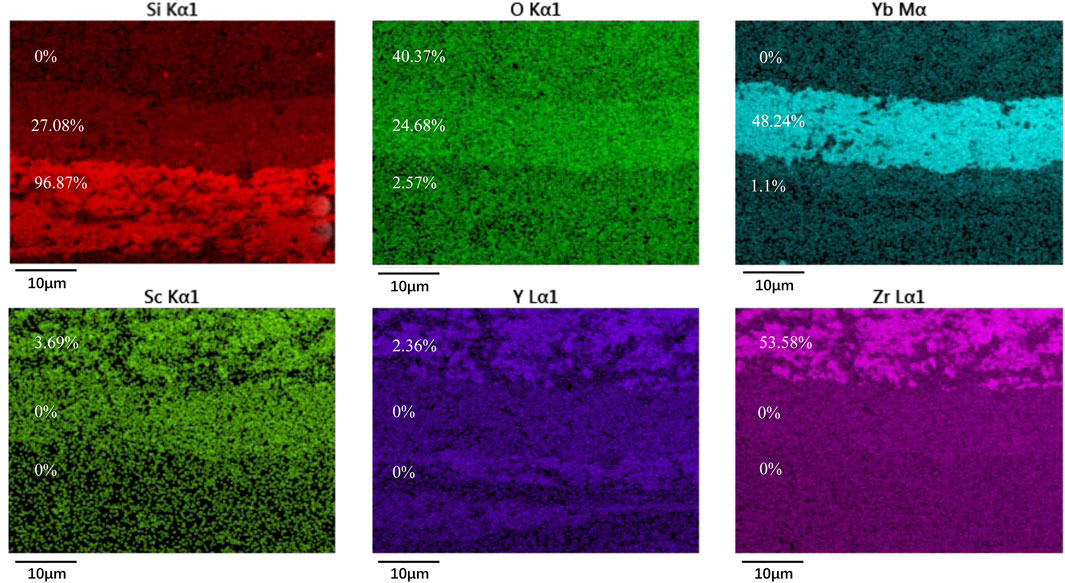
FIGURE 6. Distribution and proportion of main elements of coating.
6.3 Bonding strength
Figures 7, 8 show the average bonding strength and fracture properties for the three samples, respectively. The bonding strength of the coating increases with the contact area. The fractures of the stretched samples are all in abradable coatings, and the peeling area decreases as the contact area increases. The structure of the fabricated coating has 3 layers, and the overall bonding strength of the coating can be influenced by the bonding strength of each layer. Under the processing conditions of Table 3, the previous research of the research group (ZHANG et al., 2022) shows that the average bonding strength of Si-5%Yb2O3 layer and Yb2Si2O7 layer is (30.48 ± 4.43) MPa and (26.23 ± 3.13) MPa, respectively. And the fractures are in the SiCf/SiC composites. It can be inferred that the key factor affecting the bonding strength of coating is the Sc2O3-Y2O3-ZrO2-CaF2-PHB abradable coating rather than the Si-5%Yb2O3 coating or the Yb2Si2O7 coating.
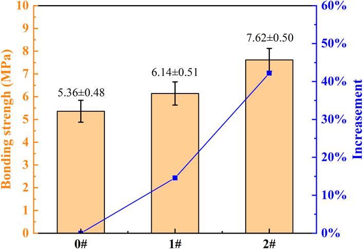
FIGURE 7. Bonding strength of three kinds of tensile samples.
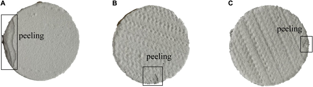
FIGURE 8. Fracture characteristics of tensile samples: (A) 0# sample; (B) 1# sample; (C) 2# sample.
In order to explore the mechanism of textures on bonding strength of coating, the increment of contact area between the coating and SiCf/SiC composite is introduced. Compared with the flat sample (0# sample), the increment of contact area of the single groove can be expressed as:
where L is length of the groove.
Based on the surface morphology result of SiCf/SiCe composites in Figure 4, it can be obtained that the increments of contact area of 1# and 2# samples compared with 0# sample are 41.3% and 104%, respectively. Therefore, the increasing bonding strength of the coating demonstrates the beneficial effect of the surface microstructure of the SiCf/SiC composite.
6.4 Stress distribution of coating
Figure 9 shows the results of the simulation of the thermal shock at 17 s for the three types of coatings. Interfaces between coatings indicate different stress profiles that are affected by the interface morphology. For the three coatings, the deeper the microstructure, the greater the difference in stress. The convex part of the groove is compressive stress, which can inhibit coating peeling. And the more grooves there are, the harder the coating will peel off. The 2# sample has a maximum interfacial compressive stress of −160MPa, which is twice that of the 0# sample. In terms of the difference in the physical parameters of the coatings, the interfacial stress of Si-5%Yb2O3/Yb2Si2O7 is 20–30 MPa larger than that of Yb2Si2O7/Sc2O3-Y2O3-ZrO2-CaF2-PHB. In addition, the pores in the abradable coating release stress to some extent. Figure 10 plots the stress variation of th ethree points in Figure 9 during the thermal shock. The internal compressive stress gradually increases as the flame heats up, and decreases as the flame stops heating.
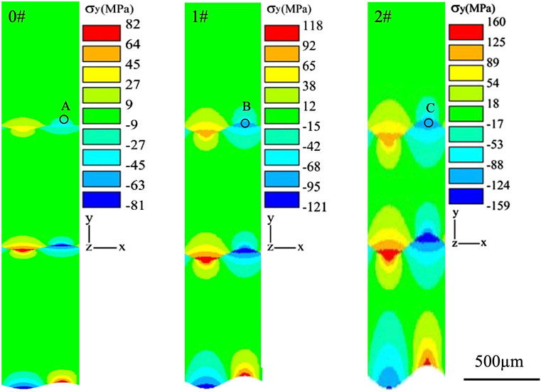
FIGURE 9. Simulation results of thermal shock.
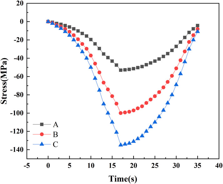
FIGURE 10. The variation of stress during the thermal shock process.
6.5 Structural integrity analysis of coating
Figure 11 shows the apparent conditions of Sc2O3-Y2O3-ZrO2-CaF2-PHB abradable coating during the thermal shock test. Compared to the 1# and 2# samples, the 0# sample is the most severely damaged. Fractures are already present at the edges after 500 thermal shocks, and multiple coating spallation occurs after 1,000 thermal shocks. Central defects tend to start at a point and gradually expand towards the edges, eventually forming a patch of spallation with the edges. For the 1# sample, cracks exist at the edges after 500 thermal shocks. As the number of thermal shocks increases, the length and width of the crack gradually expand, but the coating still does not peel off until about 2,000. The 2# sample has the best structural integrity with no cracks or peeling on the coating. Table 8 shows the thickness comparison of the samples before and after the thermal shock. The 0# sample shows significantly higher variation than the 1# and 2# samples, indicating that the coatings of the 1# and 2# samples are better adhered to the surface microstructure.
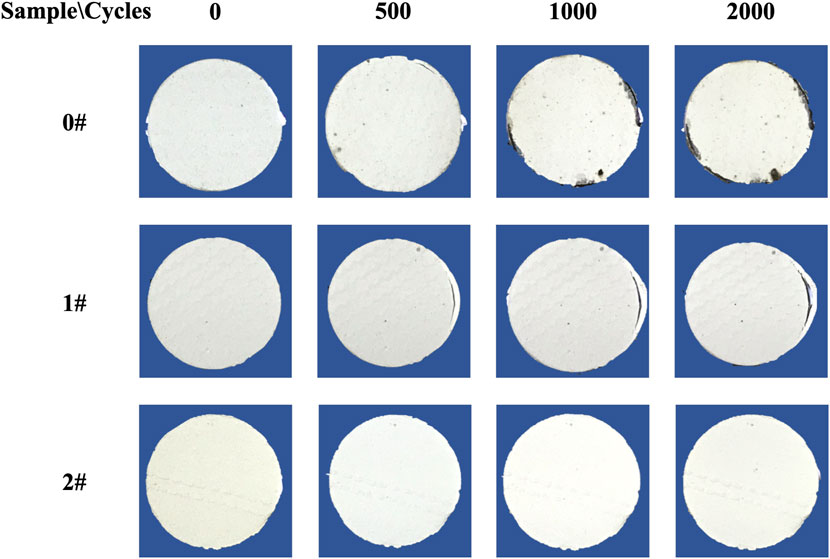
FIGURE 11. The apparent conditions of Sc2O3-Y2O3-ZrO2-CaF2-PHB abradable coating.
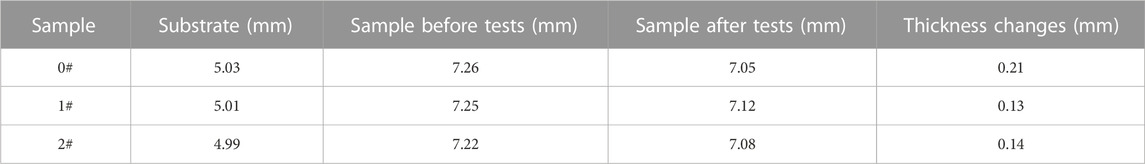
TABLE 8. The variation of coating thickness.
Figure 12 demonstrates the comparison of internal defects in the coatings before and after the thermal shock test. The 0# sample shows a large difference from the 1# and 2# samples. The 0# sample has the scattered bright spots and drops (Figure 12B) while the 1# and 2# samples only occur bright streaks (Figures 12D, F). Combined with XRD results, the abradable coating of 0# sample was pulverized and peeled off, and the Yb2Si2O7 layer which is closely combined with Si-5%Yb2O3 layer was exposed, while the abradable coatings of 1# and 2# samples still exist. It can be inferred that cracks are easily initiated and propagated in pores or poorly bonded boundary regions due to the high porosity and weak cohesion strength of abradable coatings. Furthermore, the suppression of crack propagation in the 2# sample is better than that in the 1# sample due to the larger bond strength. The width and length of the defects in the 2# sample are smaller than those in the 1# sample, so the colors of the internal defects in the 2# coating are lighter in the IR images.
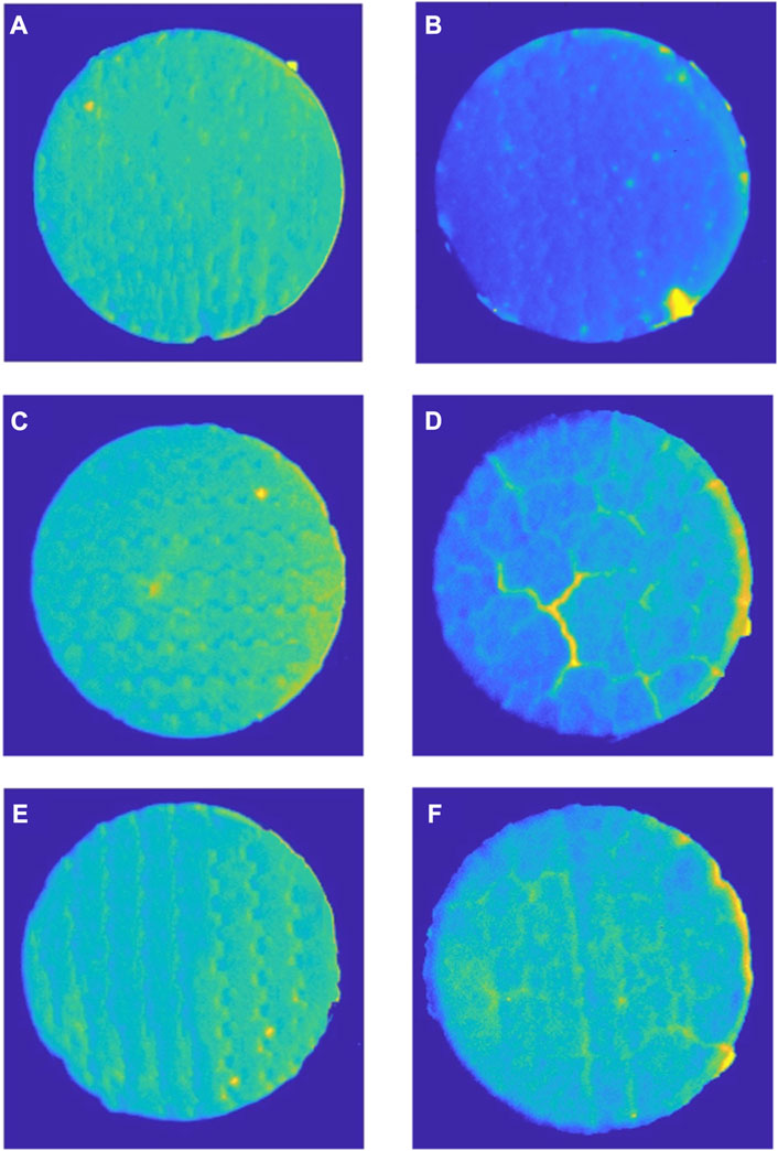
FIGURE 12. The comparison of coatings’ internal defects: (A) 0# sample before the thermal shock test; (B) 0# sample after the thermal shock test; (C) 1# sample before the thermal shock test; (D) 1# sample after the thermal shock test; (E) 2# sample before the thermal shock test; (F) 2# sample after the thermal shock test.
6.6 XRD comparison and analysis
Figure 13 shows XRD results of the outermost coating before and after the thermal shock tests. Before the tests, the phases of all the coatings are the same which contain ZrO2, CaF2 and Zr0.84Sc0.16Y0.12O2.1. However, the 0# sample indicates entirely different results while the 1# and 2# samples stay the same after the tests. In can be seen that the contents of 0# sample outermost coating are Yb2Si2O7 and ZrO2 which indicates the abradable coating fades away and the Yb2Si2O7 layer is exposed. While the outermost coatings of 1# and 2# samples are still the abradable coating. The XRD results also meet the coating thickness variations in Table 8, the thickness variation of 0# sample is the largest. The surface microstructure on the SiCf/SiC composite greatly enhances the bonding strength of abradable coating, and the thermal shock life is also increased.

FIGURE 13. XRD results of coatings before and after thermal shock tests.
7 Conclusion
A novel Sc2O3-Y2O3-ZrO2-CaF2-PHB/Yb2Si2O7/Si-5%Yb2O3 coatings were deposited on the groove structures prepared by femtosecond laser processing technology, and the coatings were subjected to the thermal shock tests at (1,250 ± 50)°C. Several results are summarized as follows.
(1) The contact area of the groove structure and the coating increased by 41.3% and 104.0%, and the bonding strength of the coatings increased by 14.6% and 42.2%, respectively. The fracture site of the tensile test is mainly inside the abradable coating.
(2) After 2000 times thermal shock test at (1,250 ± 50)°C, the abradable coating whose substrate was not surface processed was peeled off, and the Yb2Si2O7 layer was exposed. However, for abradable coatings whose substrates are surface treated, the abradable coating is not peeled off, but the thickness of the coating is reduced. The greater the contact area between the coating and the substrate, the less thin the coating thickness.
(3) The locations of cracks were mainly in the abradable coating, cracks were easy to initiate and propagate in pores or poorly bonded boundary regions, and the overall shape was shell-like. The crack propagation behavior is influenced by the matrix microstructure, and the deeper the microstructure, the less distinct the crack.
Data availability statement
The original contributions presented in the study are included in the article/Supplementary Material, further inquiries can be directed to the corresponding author.
Author contributions
J-nJ wrote the article. LZ, Q-lL, CW, and EL completed the experiments. L-hD and H-dW evaluated the grammar and innovation of the paper. All authors contributed to the article and approved the submitted version.
Funding
This work was supported by the National Science and Technology Major Project (2017-VI-0020-0092), and the National Natural Science Foundation of China (52175206).
Conflict of interest
The authors declare that the research was conducted in the absence of any commercial or financial relationships that could be construed as a potential conflict of interest.
Publisher’s note
All claims expressed in this article are solely those of the authors and do not necessarily represent those of their affiliated organizations, or those of the publisher, the editors and the reviewers. Any product that may be evaluated in this article, or claim that may be made by its manufacturer, is not guaranteed or endorsed by the publisher.
References
Arnal, S., Fourcade, S., Mauvy, F., and Rebillat, F. (2022). Design of a new yttrium silicate Environmental Barrier Coating (EBC) based on the relationship between microstructure, transport properties and protection efficiency. J. Eur. Ceram. Soc. 42 (3), 1061–1076. doi:10.1016/j.jeurceramsoc.2021.11.011
Bassaki, S., Niazi, H., Golestani-Fard, F., Naghizadeh, R., and Bayati, R. (2015). Enhanced photocatalytic activity in p-NiO grafted n-TiO2 porous coatings[J]. J. Mater. Sci. Technol. 31 (04), 355–360. doi:10.1016/j.jmst.2014.10.006
Cheng, Z., Fang, Y. E., Liu, Y., Qiao, T., Li, J., Qin, H., et al. (2019). Mechanical and dielectric properties of porous and wave-transparent Si3N4–Si3N4 composite ceramics fabricated by 3D printing combined with chemical vapor infiltration[J]. J. Adv. Ceram. 8 (3), 399–407. doi:10.1007/s40145-019-0322-8
Delebarre, C., Wagner, V., Paris, J. Y., Dessein, G., Denape, J., and Gurt-Santanach, J. (2017). Tribological characterization of a labyrinth-abradable interaction in a turbo engine application. Wear 370, 29–38. doi:10.1016/j.wear.2016.11.007
Du, J., Liu, R., Wan, F., and Wang, Y. (2022). Failure mechanism of ytterbium silicate/silicon bi-layer environmental barrier coatings on SiCf/SiC composites upon long-time water vapor and oxygen corrosion test[J]. Surf. Coatings Technol. 447, 128871. doi:10.1016/j.surfcoat.2022.128871
Eaton, H. E., and Linsey, G. D. (2002). Accelerated oxidation of SiC CMC's by water vapor and protection via environmental barrier coating approach. J. Eur. Ceram. Soc. 22 (14-15), 2741–2747. doi:10.1016/s0955-2219(02)00141-3
Hardwicke, C. U., and Lau, Y. C. (2013). Advances in thermal spray coatings for gas turbines and energy generation: A review. J. Therm. Spray Technol. 22 (5), 564–576. doi:10.1007/s11666-013-9904-0
Hu, Q., Wang, Y., Guo, X., Tu, Y., Liu, R., Song, G., et al. (2022). Oxidation inhibition behaviors of environmental barrier coatings with a Si-Yb2SiO5 mixture layer for SiCf/SiC composites at 1300° C[J]. Surf. Coatings Technol. 438, 128421. doi:10.1016/j.surfcoat.2022.128421
Huang, J., Liu, R., Hu, Q., Guo, X., Tu, Y., et al. (2023). High temperature abradable sealing coating for SiCf/SiC ceramic matrix composites[J]. Ceram. Int. 49 (2), 1779–1790. doi:10.1016/j.ceramint.2022.09.141
Jalalian, M., Jiang, Q., and Bismarck, A. (2019). Air templated macroporous epoxy foams with silica particles as property-defining additive. Acs Appl. Polym. Mater. 1, 335–343. doi:10.1021/acsapm.8b00084
Kathavate, V. S., Pawar, D. N., Bagal, N. S., and Deshpande, P. (2020). Role of nano ZnO particles in the electrodeposition and growth mechanism of phosphate coatings for enhancing the anti-corrosive performance of low carbon steel in 3.5% NaCl aqueous solution. J. Alloys Compd 823, 153812. doi:10.1016/j.jallcom.2020.153812
Kathavate, V. S., Pawar, D. N., and Adkine, A. S. (2019). Micromechanics-based approach for the effective estimation of the elastic properties of fiber-reinforced polymer matrix composite. J. Micromechanics Mol. Phys. 4, 1950005. doi:10.1142/s242491301950005x
Lamraoui, A., Costil, S., Langlade, C., and Coddet, C. (2010). Laser surface texturing (lst) treatment before thermal spraying: A new process to improve the substrate-coating adherence. Surf. Coatings Technol. 205 (7), S164–S167. doi:10.1016/j.surfcoat.2010.07.044
Piollet, E., Nyssen, F., and Batailly, A. (2019). Blade/casing rubbing interactions in aircraft engines: Numerical benchmark and design guidelines based on NASA rotor 37. J. Sound Vib. 460, 114878. doi:10.1016/j.jsv.2019.114878
Reza, M. S., Aqida, S. N., and Ismail, I. (2016a). Interface bonding of NiCrAlY coating on laser modified H13 tool steel surface[J]. Appl. Phys. A 122 (6), 1–6.
Zhang, B., and Marshall, M. (2018). Investigating the application of a honeycomb abradable lining in the turbine stage of an aero-engine. Tribol. Int. 125, 66–74. doi:10.1016/j.triboint.2018.04.013
Zhang, Le, Zhang, Yi-xin, Ya-ran, N. I. U., et al. (2022). Bonding strength of Si/Yb2Si2O7 duplex coatings on SiCf/SiC composites[J]. Surf. Technol. 51 (3), 199–207.
Keywords: plasma spraying, SiCf/SiC ceramic matrix composites, abradable coating, thermal shock, crack evaluation
Citation: Jing J-n, Zhang L, Li Q-l, Wang C, Dong L-h, Wang H-d and Lin E (2023) Improving the anti-thermal-shock properties of Sc2O3-Y2O3-ZrO2-CaF2-PHB abradable coatings by fabricating the textures on ceramic matrix composites: experiment verification and numerical analysis. Front. Mater. 10:1219121. doi: 10.3389/fmats.2023.1219121
Received: 08 May 2023; Accepted: 24 July 2023;
Published: 02 August 2023.
Edited by:
Muhamad Azizi Mat Yajid, University of Technology Malaysia, MalaysiaReviewed by:
Kamalan Kirubaharan Amirtharaj Mosas, Alexander Dubcek University in Trencin, SlovakiaVaibhav S. Kathavate, Virginia Tech, United States
Copyright © 2023 Jing, Zhang, Li, Wang, Dong, Wang and Lin. This is an open-access article distributed under the terms of the Creative Commons Attribution License (CC BY). The use, distribution or reproduction in other forums is permitted, provided the original author(s) and the copyright owner(s) are credited and that the original publication in this journal is cited, in accordance with accepted academic practice. No use, distribution or reproduction is permitted which does not comply with these terms.
*Correspondence: Jian-nong Jing, jingjiannong@126.com; Li-hong Dong, lihong.dong@126.com