Simultaneously focusing electromagnetic and acoustic waves by double-physical-fields null medium
 Boyang Wu1†
  Fei Sun1*†
  Yichao Liu1
  Xin Liu1 Xiaodan Zhao1 Hongming Fei1 Yibiao Yang1
  Zhihui Chen1 Shaowei Liang2 Zheng Wang2 Bingjie Wang1*
- 1Key Lab of Advanced Transducers and Intelligent Control System, Ministry of Education and Shanxi Province, College of Electronic Information and Optical Engineering, Taiyuan University of Technology, Taiyuan, China
- 2China-Blarus Belt and Road Joint Laboratory on Electromagnetic Environment Effect, Taiyuan, China
A novel double-physical-fields lens that can simultaneously focus acoustic and electromagnetic waves into a given region is designed based on double-physical-fields null medium, which can be realized by metal plates with subwavelength separations/thicknesses and precisely designed lengths. Numerical simulations show the proposed double-physical-fields lens can create exactly the same focusing effect for both electromagnetic and acoustic waves, i.e., the same focal spot size and efficiency at the same focal length. Four typical lens with different output surfaces are studied, which shows different focusing characteristics, e.g., noodle-shaped focal spot, tiny focal spot, and capsule-shaped focal spot. With the help of the designed double-physical-fields lens, an additional degree of freedom for control can be provided by simultaneously focusing acoustic and electromagnetic waves, which may lead to wider range of applications than single-field focusing.
1 Introduction
The focusing of acoustic wave or electromagnetic wave alone has already been applied in various important application. For example, it is an effective non-invasive way of treating tumors by focusing ultrasound/microwave onto the tumor area, where focused high ultrasound/electromagnetic energy can raise the temperature of the tumor cells to produce thermal coagulation or ablation (Sato et al., 1996; Fan et al., 2013; Shi et al., 2015; Xia and Sun, 2015). Usually, tumour treatment by focused ultrasound is more accurate than the treatment by focused microwave. However, some tissues (e.g., esophagus and rectum) cannot be penetrated by ultrasound and can only be treated by focused microwave. Acoustic/electromagnetic tweezers, which can capture the target particles noninvasively by forces and torques generated from the focused acoustic/electromagnetic fields, have been widely used to manipulate the movement of micro-nano particles (e.g., biological molecules and living cells) (Janssen et al., 2012; Ozcelik et al., 2018; Vidiasheva et al., 2018; Marzo and Drinkwater, 2019). Currently, the focused acoustic beam can be achieved by acoustic metasurfaces/metamaterials (Zhang et al., 2009; Qi et al., 2017; Xia et al., 2018), negative or zero refractive index lenses (Fang et al., 2006; Gao et al., 2016), acoustic crystal lens (Yang et al., 2004), graded index lens (Li et al., 2012), anisotropic material lens (Li et al., 2017), and etc. Common methods of focusing electromagnetic waves include various electromagnetic lenses (Kwon and Werner, 2009; Kundtz and Smith, 2010; Roy et al., 2013; Khorasaninejad et al., 2016; Chen et al., 2018), time reversal mirrors (Lerosey et al., 2004; de Rosny et al., 2010), structures designed by deep learning methods (Rivenson et al., 2017; Ma et al., 2021), and etc.
Compared with single-physical-field focusing, focusing acoustic and electromagnetic waves simultaneously has better application value. If the simultaneous focus of acoustic and electromagnetic waves can be achieved, the advantages of the two focused physical fields can complement each other. In tumor therapy, simultaneous focused ultrasound and microwave will provide both the high precision of focused acoustic waves for tumour treatment (Kohrmann et al., 2002) and the high penetration of focused microwaves for tumour treatment (Leggio et al., 2015; Lim and Yoon, 2021). Double-physical-fields tweezers by simultaneous focused ultrasound and microwave can provide additional degrees of freedom in the manipulation of captured targets, e.g., the focused acoustic beam can capture targets in the given region while the focused electromagnetic beam can rotate them at the same time. In industrial inspection, the focused acoustic wave can be used to locate cracks in pipes and castings, while the focused electromagnetic beam can help to repair these cracks (e.g., the thermal effect of focused infrared waves can help repair cracks by dissolving the material at the crack). In double-field focusing, the focused acoustic waves may image/capture/locate the target, and the focused electromagnetic waves may simultaneously perform an additional manipulation (e.g., destruction/rotation/repairment) on the same target. In recent years, various structures have been designed to simultaneously manipulate electromagnetic and acoustic waves, such as electromagnetic-acoustic cloaking (Sun et al., 2020), electromagnetic shielding and sound absorption (Gao et al., 2022), and electromagnetic-acoustic splitter (Chen et al., 2023). However, there is little research on how to achieve simultaneous focusing of electromagnetic and acoustic waves with the same structure.
In order to focus acoustic and electromagnetic waves simultaneously, a novel double-physical-fields lens (DPFL) is proposed in Figure 1. The designed DPFL can be realized by metal plates with subwavelength separations/thicknesses and precisely designed lengths, which performs as a reduced double-physical-fields null medium that can convert the incident electromagnetic/acoustic wavefront on the input surface of the lens into the desired electromagnetic/acoustic wavefront on the output surface of the lens (Sun et al., 2020). Note that the ‘subwavelength’ means the size of the separation and thickness of the metal plates are smaller than the wavelength of the electromagnetic/acoustic wave, e.g., one-third of the working wavelength.
FIGURE 1. Schematic diagram of the DPFL by sub-wavelength air channels enclosed by metal plates.
2 Design method
Double-physical-fields null medium, which performs as a perfect endoscope for electromagnetic waves and acoustic waves simultaneously, has been theoretically studied (Sun et al., 2020). Based on the perfect directional projection properties of the double-physical-fields null medium, double-physical-fields surface transformation has been proposed in our previous study (Sun et al., 2020), which is a graphical method to design double-physical-fields devices. In this study, we use double-physical-fields surface transformation to design DPFL that can focus both electromagnetic waves and acoustic waves into the same focal point. The parameters of the ideal double-physical-fields null medium can be obtained from the extreme space compression transform by transformation optics and transformation acoustics, which can be summarized as (Sun et al., 2020):
From Eq. 1, the permittivity, permeability and modulus of the ideal double-physical-fields null medium are extremely anisotropic, whose values approach infinity along their main axis and are close to zero in other orthogonal directions. After some theoretical calculations (Sun et al., 2020), it shows that the metallic plates with subwavelength separations and thicknesses, whose lengths satisfy the Fabry-Perot resonance condition, can perform as a reduced double-physical-fields null medium. The reduced double-physical-fields null medium can still project TM-polarized electromagnetic waves and acoustic waves simultaneously along the orientations of metallic plates.
As shown in Figure 1, the input and output surfaces of the DPFL are designed as a plane and a curved surface (described by the equation y = f (x)), respectively. The DPFL is composed by an array structure of 2N + 1 parallel metal plates with equally subwavelength separation d and thickness t. 2N air channels are formed between two adjacent metal plates, which are labeled from the centre of the lens outwards as channel 1, channel 2, … and channel N. The size of the input surface of the DPFL is h = 2Nd + t, which can be adjusted by increasing or decreasing the number of metal plates for matching the width of the incident wave. The length of the k-th air channel approximately satisfying the Fabry-Perot resonance condition (i.e., Lk = mλ0, m = 1, 2, 3…, where λ0 is the working wavelength) to obtain the best transmittance, which is defined as the efficiency of the DPFL for electromagnetic waves (Xia et al., 2018):
where S is the Poynting vector (i.e., the energy flow density vector), l and h are the transverse sizes of the focusing spot and input surface along the y-axis, respectively (see Figure 1). Although there is no concept of Poynting’s vector for acoustic waves, the z component of magnetic field Hz field for TM polarized electromagnetic waves and the acoustic pressure for acoustic waves satisfy the same Heimholtz equation, and the subsequent simulation results show that the designed structure has exactly the same focusing effect on both magnetic field and acoustic pressure, therefore the efficiency defined by Eq. 2 is also suitable for the focusing efficiency of acoustic wave.
In this study, the efficiency of the lens is calculated as follows: we first remove the DPFL and calculate the integration of the incident energy flow over the air surface with the same size of the DPFL’s input surface, which gives the denominator of Eq. 2, i.e., the total incident energy. Then, we add the DPFL and calculate the integration of energy flow density over the width of the focused spot, which gives the numerator of Eq. 2, i.e., the energy at the focused spot. Since all simulations show that the lens produces exactly the same field distribution for both electromagnetic wave and acoustic wave, the simulated results for electromagnetic waves are used to calculate the lens efficiency in the subsequent optimization calculations.
The designed DPFL by metal plates in Figure 1 performs as reduced double-physical-fields null medium for TM-polarized electromagnetic and acoustic waves, whose function is to simultaneously project the electromagnetic/acoustic field distributions from the input surface along the direction of the air channel onto the output surface (Sun et al., 2020). When the wavefront of the incident EM wave/acoustic wave coincides with the shape of the DPFL’s input surface (e.g., plane wave), the wavefront of the outgoing wave can be converted to coincide with the shape of the DPFL’s output surface after passing through the DPFL. Therefore, a double-physical-field focusing effect can be obtained by designing various geometrical shapes of output surfaces.
3 Simulation results for various DPFLs
The double-physical-fields focusing effect of various DPFLs with different output surfaces are studied numerically. All numerical simulations in this study are carried out by COMSOL Multiphysics 5.6 (license number 9406999). All numerical simulations are 2D simulations in this study, which means that the metal plates are infinite along the z direction. The radio frequency module and the acoustic module are utilized to calculate electromagnetic field distribution and acoustic pressure distribution, respectively. The working wavelength is designed as λ0 = 30 mm, which corresponds to the working frequencies 10 GHz for electromagnetic wave and 11.4 kHz for acoustic wave, respectively. The metal is modeled as perfect electric conductor and hard wall boundary condition for electromagnetic simulation and acoustic simulation, respectively. Note that metallic plates can perform as reduced null medium for only TM-polarized electromagnetic waves, we only simulate the DPFLs for TM-polarized electromagnetic waves in this study. The double-physical-fields focusing effect of DPFLs with four different shapes of the output surface are studied, which include the parabolic surface in Figure 2, the hyperbolic surface in Figure 3, the elliptical surface in Figure 4, and the circular surface in Figure 5.
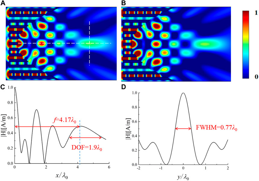
FIGURE 2. Simulated normalized magnetic field distribution (A) and normalized acoustic pressure distribution (B), respectively, when a TM-polarized plane electromagnetic wave and a plane acoustic wave are incident onto the designed DPFL with a parabolic output surface f(x) =
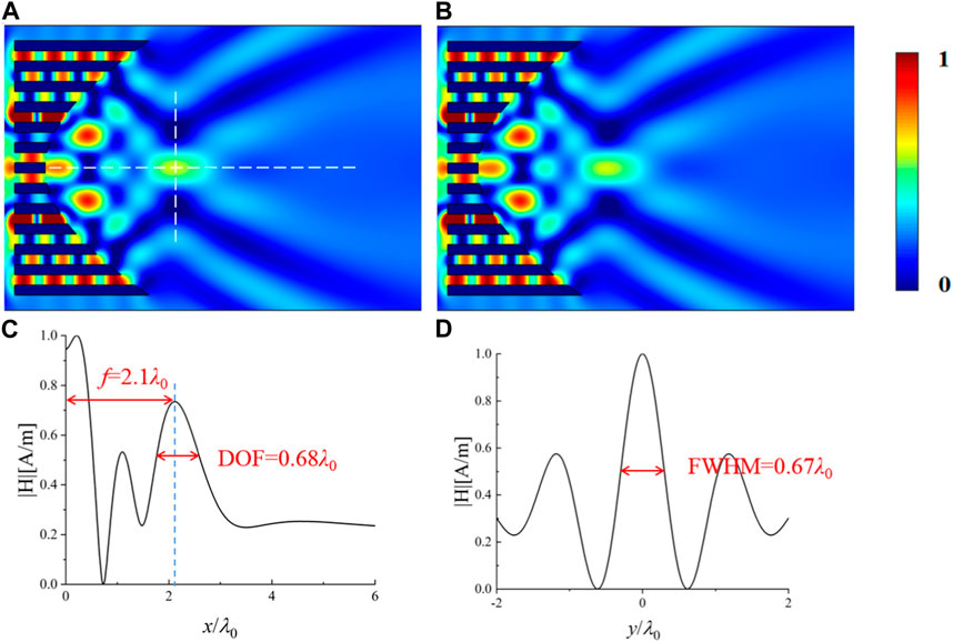
FIGURE 3. Simulated normalized magnetic field distribution (A) and normalized acoustic pressure distribution (B), respectively, when a TM-polarized plane electromagnetic wave and a plane acoustic wave are incident onto the designed DPFL with a hyperbolic output surface equation f(x) = 70
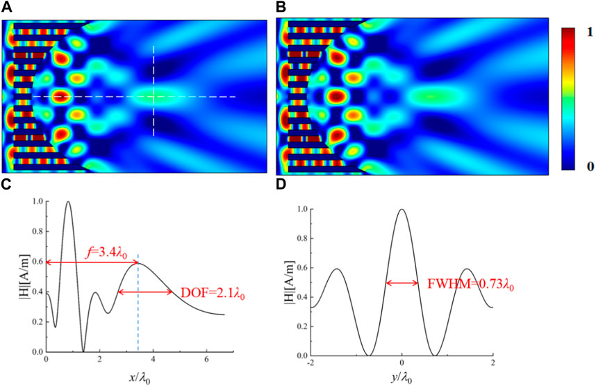
FIGURE 4. Simulated normalized magnetic field distribution (A) and normalized acoustic pressure distribution (B), respectively, when a TM-polarized plane electromagnetic wave and a plane acoustic wave are incident onto the designed DPFL with an elliptical output surface equation f(x) = 70

FIGURE 5. Simulated normalized magnetic field distribution (A) and normalized acoustic pressure distribution (B), respectively, when a TM-polarized plane electromagnetic wave and a plane acoustic wave are incident onto the designed DPFL with a circular output surface equation f(x) =
The designed working wavelength (λ0 = 30 mm) and corresponding frequencies (11.4 kHz and 10 GHz for acoustic and electromagnetic waves, respectively) is used as one example in this study, which can be changed to other values according to different applications. For example, we can first determine the required acoustic frequency for a specific application (e.g., ultrasonic detection), and then the new working wavelength can be calculated accordingly, thereafter the parameters of the DPELs can be redesigned by using Fabry-Perot resonance condition Ln = mλ0, m = 1, 2, 3…, where λ0 is the new working wavelength.
The lens designed in this study involves metal and air. For air, it can be considered a loss-free material for both electromagnetic and acoustic waves. Considering the conductivities of metals are extremely high (e.g., the conductivity of the copper is 6*107 [S/m]) in the microwave band (the designed working frequency 10 GHz), whose skin depth can be treated as zero (modeled as perfect electric conductor), the material loss of the metal has essentially no effect on the focusing effect of the electromagnetic waves in the designed working frequency. Similarly, metals can usually be treated as a hard wall boundary condition for acoustic waves (Yang et al., 2016), i.e., acoustic waves cannot enter. Therefore, the material loss of the metal has no effect on the focusing effect of the acoustic waves.
The simulated results verify the designed DPFL with a parabolic output surface (i.e., the equation of the output surface is chosen as a parabolic equation f(x) =
Please note that the amplitudes of magnetic field and acoustic pressure are normalized, which leads to a range of values between 0 (minimum) and 1 (maximum), and the color bars in all figures are in the range 0–1. In this case, the blue regions in the color bar indicate that the amplitude of magnetic field or acoustic pressure at these positions are zero ‘0’, the red regions in the color bar indicate that the amplitude of magnetic field or acoustic pressure at these positions are the maximum ‘1’, and the other colors mean that the amplitude of magnetic field or acoustic pressure are between the zero ‘0’ and the maximum “1”.
The hyperbolic DPFL, whose output surface satisfy a hyperbolic equation f(x) = 70
The elliptical DPFL, whose output surface satisfy a elliptical equation f(x) = 70
The circular DPFL, whose output surface satisfy a circular equation f(x) =
Theoretically, according to the double-physical-fields surface transformation theory, when the output surface of the lens is chosen to be of different geometrical shapes, the wave front of the output wave will be modulated to that shape accordingly. In this design, the output surfaces are designed as parabola, hyperbola, ellipse and circle, respectively, and according to the nature of perfect projection of null medium, the wave fronts of the output waves are modulated into these four surfaces accordingly. In these four cases, the output wave is focused at the focal point of the parabola/hyperbola/ellipse and at the centre of the circle, and the position of the focal point can be adjusted by changing the geometrical parameters of the corresponding output surface.
The key parameters of the DFPL with four different output surfaces are given in Tab. 1, which can be a guidance for different applications. For the parabolic DPFL, the energy of the sidelobe is concentrated before the focal point, and the energy distribution of the sidelobe is weaker after the focal point and the focal plane, which leads to a relatively high efficiency (∼31.42%). The focal spot of the parabolic DPFL is capsule-like spot with a relatively moderate size (FWHM∼0.77λ0 and DOF∼1.9λ0), and the long focal length is relatively long (f ∼ 4.17λ0). For the hyperbolic DPFL, the energy of the sidelobe is distributed before and after focusing plane, which in turn leads to lower efficiency (∼26.86%). The hyperbolic DPFL can produce the smallest focal spot with very compact sizes in both horizontal direction (DOF = 0.68λ0) and vertical direction (FWHM = 0.67λ0) at the shortest focal length f = 2.1λ0, which is very suitable for precisely confining tiny objects to small area. For the elliptical DPFL, the energy of the sidelobe is distributed before and after focusing plane, which has the lowest efficiency (∼22.37%). The elliptical DPFL can create a capsule-shaped spot with a relatively moderate size (FWHM∼0.73λ0 and DOF∼2.1λ0) and moderate focal length (f ∼ 3.4λ0). For the circular DPFL, the energy of the sidelobe is concentrated before the focal point, and the energy distribution of the sidelobe is weaker after the focal point and the focal plane, which has the highest efficiency (∼37.71%). The circular DPFL can produce a noodle-shaped focal spot at the longest focal length (f ∼ 6.7λ0), which can be used for noninvasive processing/treatment that requires penetration of surfaces (e.g., inside pipes and human bones). In summary, elliptical/parabolic DPFLs are moderate-focal-length lenses with moderate focal spot sizes, hyperbolic DPFL is short-focal-length lens with smallest focal spot size, and circular DPFL is long-focal-length lens with noodle-shaped focal spot.
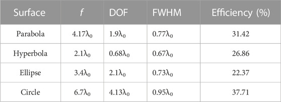
TABLE 1. Key parameters of the DPFLs with different output surfaces.
4 Parameters scanning
From the above analysis, the parabolic DPFL has relatively moderate parameters, which is chosen as an example to study how to further improve the efficiency of the DPFL by choosing suitable structural parameters. Simulation results show separation distance d in Figure 1 and surface parameter A (f(x) =
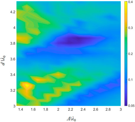
FIGURE 6. Efficiency of the parabolic DPFL when parameters d and A are scanned.
If d is too large, then the metal plates in Figure 1 will no longer behave as an effective medium for double fields; while if d is too small, it is difficult to ensure that each channel approximately meets the Fabry-Perot resonance condition, thus the scan range of d is limited to d = 3λ0 ∼ 4.3λ0 in Figure 6. If A is too small, the shape of the output surface will be reduced to a plane, and the focusing effect will disappear; while if A is too large, more number of metal plates are required to mimic the sharp curvature variation at the output surface, which is difficult to ensure that each channel approximately meets the Fabry-Perot resonance condition, thus the scanning range of A is limited to A = 1.4λ0 ∼ 3λ0 in Figure 6.
During the scanning, the number of air channels 2N = 12, the thickness of the metal plate t = d/2, and the working wavelength λ0 = 30 mm are kept unchanged. As shown in Figure 6, the best efficiency η = 37.59% can be obtained when d = 3.27λ0 and A = 1.5λ0 for the optimized parabolic DPFL. The optimized parabolic DPFL with a higher energy utilization can still focus both electromagnetic and acoustic waves simultaneously with a relatively moderate size (FWHM = 0.59λ0 and DOF = 1.93λ0) and focal length (f = 4.3λ0), which is verified by numerical simulations in Figure 7.
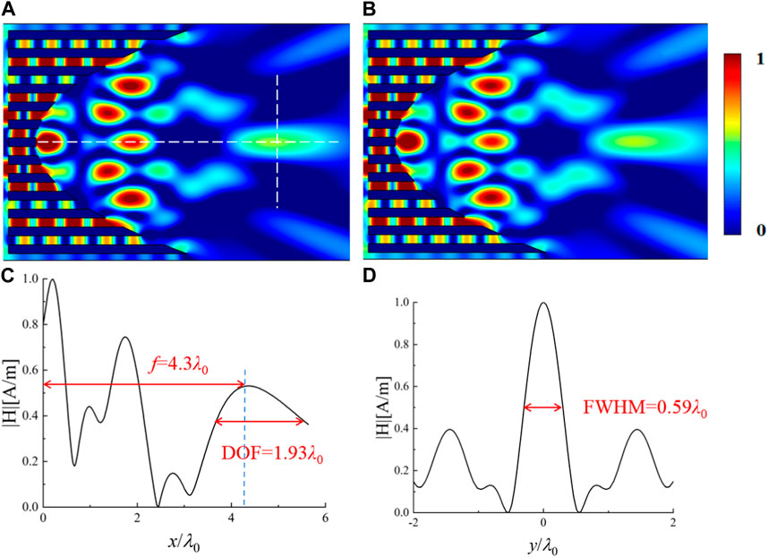
FIGURE 7. Simulated normalized magnetic field distribution (A) and normalized acoustic pressure distribution (B), respectively, when a TM-polarized plane electromagnetic wave and a plane acoustic wave are incident onto the optimized parabolic DPFL with a output surface
For a perfect DPFL realized by ideal double-physical-fields null medium, the shape of the outgoing wave should be exactly the same as the shape of the output surface. However, for the reduced null medium by metallic array, the length of each air channel must be an integer multiple of the wavelength to obtain the best transmittance, which leads to the shape of the outgoing wave is not exactly the same as the output surface. In this case, the focal point is the result of the interference of the outgoing waves from multiple air channels, which results in a non-peak energy at the focal point along the x axis. To solve this problem, the waveguide metamaterials (Zheng et al., 2019), instead of an array of metal plates, can be used to realize the reduced null medium, where the FP condition does not need to be satisfied for each channel. In this case, the energy at the focal point can be a peak along the x axis. However, such a lens based on waveguide metamaterials would only be effective for electromagnetic waves and cannot be able to focus both electromagnetic and acoustic waves.
Our design principle is different from the current method on designing metasurfaces, which often needs to numerically calculate the phase shift and transmittance of each metasurface, and then adjust the geometric parameters of each unit to make its transmittance phase satisfy a specific distribution (on the premise of ensuring that the transmittance of each unit is close to 1) to achieve the focusing or other desired effect (Liu et al., 2020; Cai et al., 2021). In our design method, metal channels are used to mimic null medium for both electromagnetic wave and acoustic wave, which perform as the reduced null medium (Sun et al., 2020; Chen et al., 2023). For the ideal null medium, the transmittance should be 100% and the transmission phase should be zero. In this case, the wavefront of the output wave can be directly modulated by changing the geometry of the output surface. To achieve the ideal null medium, the length of each metallic channel needs to be close to an integer multiple of the operating wavelength (i.e., the FP condition) to ensure that the transmittance is close to 1 while the transmission phase is almost 0. Therefore, we do not plot the phase shift and transmittance of each metallic channel. From the simulation results in Figures 2–5, it can be seen that a stable integer number of half standing waves are generated in each metal channel, i.e., the desired FP resonance conditions are met.
In this study, the sound and electromagnetic waves are focused at the same wavelength by the designed DPFL. If we want to simultaneously focus acoustic and electromagnetic waves at individually different wavelengths rather than the same one, some gas [e.g., hydrogen (Li et al., 2017)] may be filled in each metallic channel instead of air. In this case, the effective optical path and acoustic path are different in each metallic channel, which will lead to different wavelengths that satisfy the FP resonance condition for electromagnetic wave and acoustic wave. As the FP resonance condition should be satisfied for each metal channel to mimic null medium for both electromagnetic wave and acoustic wave, the focusing performance of the designed lens is not broadband. The focusing efficiency of the designed lens may be improved by adding some internal structures inside of each metallic channel (see arXiv:2305.00910). The proposed lens is a bulk lens, which has the curved output surface. To achieve a flat lens, metasurface may be a good choice (Liu et al., 2020; Cai et al., 2021). However, the current metasurface can only work for single-physical-field (i.e., electromagnetic wave or acoustic wave). Many prior groundwork are still needed to achieve metasurface-based flat lens for double-physical-field focusing.
5 Conclusion
By designing sub-wavelength air channels surrounded by metal plates, which performs as reduced double-physical-fields null medium, a DPFL lens that can simultaneously focus both electromagnetic and acoustic waves is designed. By adjusting the geometrical shape of the output surface, the focal spot size and focal length for both fields can be modified. Four typical DPFL lenses with different output surfaces are numerically studied, which shows different focusing characteristics and key parameters, e.g., long focal length and noodle-shaped spot for circular DPFL, short focal length and tiny spot for hyperbolic DPFL, and capsule-shaped spot with a moderate size for parabolic/elliptical DPFLs. As an example, the relationship between the key parameters of the parabolic DPFL and its efficiency is studied. This study provides a new way to focus electromagnetic and acoustic waves simultaneously, which may provide an additional degree of freedom for modulation than single-field focusing and have potential applications in medical therapy, sensors/detectors and tweezers.
Data availability statement
The original contributions presented in the study are included in the article/supplementary material, further inquiries can be directed to the corresponding authors.
Author contributions
BW and FS contributed equally to this work. BW and FS wrote and edited the manuscript together. BW performed theoretical analysis and numerical simulations. FS conceived this work, made conceptualization and supervised the work. YL, XL, and XZ helped on simulations. YY, ZC, SL, ZW, and BW helped on revising of the manuscript. FS and BW provide funding support. All authors contributed to the article and approved the submitted version.
Funding
This study is supported by the National Natural Science Foundation of China (Grant Nos. 61971300 and 12274317), Open Foundation of China-Belarus Belt and Road Joint Laboratory on Electromagnetic Environment Effect (No. ZBKF2022031202), 2022 University Outstanding Youth Foundation of Taiyuan University of Technology, and Scientific and Technological Innovation Programs (STIP) of Higher Education Institutions in Shanxi (Nos. 2019L0159 and 2019L0146).
Conflict of interest
The authors declare that the research was conducted in the absence of any commercial or financial relationships that could be construed as a potential conflict of interest.
Publisher’s note
All claims expressed in this article are solely those of the authors and do not necessarily represent those of their affiliated organizations, or those of the publisher, the editors and the reviewers. Any product that may be evaluated in this article, or claim that may be made by its manufacturer, is not guaranteed or endorsed by the publisher.
References
Banerji, S., Meem, M., Majumder, A., Sensale-Rodriguez, B., and Menon, R. (2020). Extreme-depth-of-focus imaging with a flat lens. Optica 7, 214–217. doi:10.1364/optica.384164
Cai, T., Tang, S., Zheng, B., Wang, G., Ji, W., Qian, C., et al. (2021). Ultrawideband chromatic aberration-free meta-mirrors. Adv. Photonics 3, 016001. doi:10.1117/1.ap.3.1.016001
Chen, W. T., Zhu, A. Y., Sanjeev, V., Khorasaninejad, M., Shi, Z., Lee, E., et al. (2018). A broadband achromatic metalens for focusing and imaging in the visible. Nat. Nanotechnol. 13, 220–226. doi:10.1038/s41565-017-0034-6
Chen, Z., Sun, F., Ma, X., Chen, H., Chao, K., Liu, Y., et al. (2023). Electromagnetic-acoustic splitter with a tunable splitting ratio based on copper plates. Opt. Lett. 48, 3407–3410. doi:10.1364/ol.492941
de Rosny, J., Lerosey, G., and Fink, M. (2010). Theory of electromagnetic time-reversal mirrors. Ieee. Trans. Biomed. Eng. 58, 3139–3149. doi:10.1109/tap.2010.2052567
Fan, T., Liu, Z., Zhang, D., and Tang, M. (2013). Comparative study of lesions created by high-intensity focused ultrasound using sequential discrete and continuous scanning strategies. Ieee. Trans. Biomed. Eng. 60, 763–769. doi:10.1109/tbme.2011.2167719
Fang, N., Xi, D., Xu, J., Ambati, M., Srituravanich, W., Sun, C., et al. (2006). Ultrasonic metamaterials with negative modulus. Nat. Mat. 5, 452–456. doi:10.1038/nmat1644
Gao, H., Gu, Z., Liang, B., Zou, X., Yang, J., Yang, J., et al. (2016). Acoustic focusing by symmetrical self-bending beams with phase modulations. Appl. Phys. Lett. 108, 073501. doi:10.1063/1.4941992
Gao, N., Guo, X., Deng, J., and Cheng, B. (2022). Design and study of a hybrid composite structure that improves electromagnetic shielding and sound absorption simultaneously. Compos. Struct. 280, 114924. doi:10.1016/j.compstruct.2021.114924
Janssen, X. J. A., Lipfert, J., Jager, T., Daudey, R., Beekman, J., and Dekker, N. H. (2012). Electromagnetic torque tweezers: A versatile approach for measurement of single-molecule twist and torque. Nano Lett. 12, 3634–3639. doi:10.1021/nl301330h
Khorasaninejad, M., Chen, W. T., Devlin, R. C., Oh, J., Zhu, A. Y., and Capasso, F. (2016). Metalenses at visible wavelengths: Diffraction-limited focusing and subwavelength resolution imaging. Science 352, 1190–1194. doi:10.1126/science.aaf6644
Kohrmann, K. U., Michel, M. S., Gaa, J., Marlinghaus, E., and Alken, P. (2002). High intensity focused ultrasound as noninvasive therapy for multilocal renal cell carcinoma: Case study and review of the literature. J. Urol. 167, 2397–2403. doi:10.1016/s0022-5347(05)64992-0
Kundtz, N., and Smith, D. R. (2010). Extreme-angle broadband metamaterial lens. Nat. Mat. 9, 129–132. doi:10.1038/nmat2610
Kwon, D., and Werner, D. (2009). Beam scanning using flat transformation electromagnetic focusing lenses. IEEE Antennas Wirel. Propag. Lett. 8, 1115–1118. doi:10.1109/lawp.2009.2033619
Leggio, L., de Varona, O., and Dadrasnia, E. (2015). A comparison between different schemes of microwave cancer hyperthermia treatment by means of left-handed metamaterial lenses. Prog. Electromagn. Res. 150, 73–87. doi:10.2528/pier14101408
Lerosey, G., de Rosny, J., Tourin, A., Derode, A., Montaldo, G., and Fink, M. (2004). Time reversal of electromagnetic waves. Phys. Rev. Lett. 92, 193904. doi:10.1103/physrevlett.92.193904
Li, B., Sun, F., and He, S. (2017). Acoustic surface transformation realized by acoustic-null materials using bilayer natural materials. Appl. Phys. Express 10, 114001. doi:10.7567/apex.10.114001
Li, Y., Liang, B., Tao, X., Zhu, X., Zou, X., and Cheng, J. (2012). Acoustic focusing by coiling up space. Appl. Phys. Lett. 101, 233508. doi:10.1063/1.4769984
Lim, S., and Yoon, Y. J. (2021). Phase compensation technique for effective heat focusing in microwave hyperthermia systems. Appl. Sci. Basel 11, 5972. doi:10.3390/app11135972
Liu, Y., Fu, J., Dong, H., Gong, C., Sun, F., and He, S. (2020). Extending the scanning angle of a phased-array antenna using a thin radome of curved metasurface. Phys. Status Solidi-R 14, 1900624. doi:10.1002/pssr.201900624
Ma, W., Liu, Z., Kudyshev, Z. A., Boltasseva, A., Cai, W., and Liu, Y. (2021). Deep learning for the design of photonic structures. Nat. Photonics 15, 77–90. doi:10.1038/s41566-020-0685-y
Marzo, A., and Drinkwater, B. W. (2019). Holographic acoustic tweezers. Pnas 116, 84–89. doi:10.1073/pnas.1813047115
Ozcelik, A., Rufo, J., Guo, F., Gu, Y., Li, P., Lata, J., et al. (2018). Acoustic tweezers for the life sciences. Nat. Methods 15, 1021–1028. doi:10.1038/s41592-018-0222-9
Qi, S., Li, Y., and Assouar, B. (2017). Acoustic focusing and energy confinement based on multilateral metasurfaces. Phys. Rev. Appl. 7, 054006. doi:10.1103/physrevapplied.7.054006
Rivenson, Y., Gorocs, Z., Gunaydin, H., Zhang, Y., Wang, H., and Ozcan, A. (2017). Deep learning microscopy. Optica 4, 1437–1443. doi:10.1364/optica.4.001437
Roy, T., Rogers, E. T. F., and Zheludev, N. I. (2013). Sub-wavelength focusing meta-lens. Opt. Express 21, 7577–7582. doi:10.1364/oe.21.007577
Sato, M., Watanabe, Y., Ueda, S., Iseki, S., Abe, Y., Sato, N., et al. (1996). Microwave coagulation therapy for hepatocellular carcinoma. Gastroenterology 110, 1507–1514. doi:10.1053/gast.1996.v110.pm8613057
Shi, H., Liu, T., Fu, C., Li, L., Tan, L., Wang, J., et al. (2015). Insights into a microwave susceptible agent for minimally invasive microwave tumor thermal therapy. Biomaterials 44, 91–102. doi:10.1016/j.biomaterials.2014.12.035
Sun, F., Liu, Y., and He, S. (2020). Surface transformation multi-physics for controlling electromagnetic and acoustic waves simultaneously. Opt. Express 28, 94–106. doi:10.1364/oe.379817
Vidiasheva, I. V., Abalymov, A. A., Kurochkin, M. A., Mayorova, O. A., Lomova, M. V., German, S. V., et al. (2018). Transfer of cells with uptaken nanocomposite, magnetite-nanoparticle functionalized capsules with electromagnetic tweezers. Biomater. Sci. 6, 2219–2229. doi:10.1039/c8bm00479j
Xia, J. P., and Sun, H. X. (2015). Acoustic focusing by metal circular ring structure. Appl. Phys. Lett. 106, 392–396. doi:10.1063/1.4908117
Xia, J., Zhang, X., Sun, H., Yuan, S., Qian, J., and Ge, Y. (2018). Broadband tunable acoustic asymmetric focusing lens from dual-layer metasurfaces. Phys. Rev. Appl. 10, 014016. doi:10.1103/physrevapplied.10.014016
Yang, S., Page, J. H., Liu, Z., Cowan, M. L., Chan, C. T., and Sheng, P. (2004). Focusing of sound in a 3d phononic crystal. Phys. Rev. Lett. 93, 024301. doi:10.1103/physrevlett.93.024301
Yang, Y., Wang, H., Yu, F., Xu, Z., and Chen, H. (2016). A metasurface carpet cloak for electromagnetic, acoustic and water waves. Sci. Rep. 6, 20219. doi:10.1038/srep20219
Zhang, S., Yin, L., and Fang, N. (2009). Focusing ultrasound with an acoustic metamaterial network. Phys. Rev.Lett. 102 (19), 194301. doi:10.1103/physrevlett.102.194301
Keywords: null medium, double-physical-fields lens, double-physical-fields focusing, surface transformation, transformation optics
Citation: Wu B, Sun F, Liu Y, Liu X, Zhao X, Fei H, Yang Y, Chen Z, Liang S, Wang Z and Wang B (2023) Simultaneously focusing electromagnetic and acoustic waves by double-physical-fields null medium. Front. Mater. 10:1229164. doi: 10.3389/fmats.2023.1229164
Received: 26 May 2023; Accepted: 25 July 2023;
Published: 02 August 2023.
Edited by:
Fuyin Ma, Xi’an Jiaotong University, ChinaReviewed by:
Jianping Xia, Duke University, United StatesNansha Gao, Northwestern Polytechnical University, China
Yan-Feng Wang, Tianjin University, China
Copyright © 2023 Wu, Sun, Liu, Liu, Zhao, Fei, Yang, Chen, Liang, Wang and Wang. This is an open-access article distributed under the terms of the Creative Commons Attribution License (CC BY). The use, distribution or reproduction in other forums is permitted, provided the original author(s) and the copyright owner(s) are credited and that the original publication in this journal is cited, in accordance with accepted academic practice. No use, distribution or reproduction is permitted which does not comply with these terms.
*Correspondence: Fei Sun, sunfei@tyut.edu.cn; Bingjie Wang, wangbingjie@tyut.edu.cn
†These authors have contributed equally to this work