Post-consolidation process for modifying microscale and mesoscale parameters of 3D printed composite materials
 Arief Yudhanto
 Alwaleed Aldhirgham2
 - 1Department of Mechanical Engineering, Baylor University, Waco, TX, United States
- 2Mechanics of Composites for Energy and Mobility Laboratory, Mechanical Engineering Program, Physical Science and Engineering Division, King Abdullah University of Science and Technology (KAUST), Thuwal, Saudi Arabia
- 3Robotics, Intelligent Systems and Control Laboratory, Computer, Electrical and Mathematical Science (CEMSE) Division, King Abdullah University of Science and Technology (KAUST), Thuwal, Saudi Arabia
Advancements in additive manufacturing technology (3D printing) have enabled us to fabricate reasonably good parts using continuous fiber-reinforced matrix composites. Unfortunately, most of these 3D-printed composite parts inherently possess a large number of voids originating from the trapped air within and between molten composite beads during the deposition stage. Removing the voids has thus become a key challenge in attempts to apply 3D printed composite parts for fabricating stiff/strong load-bearing structures. Here, we employed a classical process, viz. compression molding, to post-consolidate 3D-printed continuous carbon fiber-reinforced polyamide (CFPA), and to investigate the implications in terms of microscale parameters (void content) and mesoscale parameters (mechanical properties, plasticity, damage) using matrix-dominated lay-up of [±45]2s. We found that the proposed post-consolidation process could reduce the void of 3D-printed CFPA from 12.2% to 1.8%, enhancing the shear modulus and shear strength by 135% and 116%, respectively. The mesoscale analysis shows that, albeit with less ductility, the post-consolidated CFPA laminate was more resistant to damage than the 3D-printed CFPA. Classical compression molding is thus a promising technique for improving the physical and mechanical performances of 3D-printed composites by reducing inherent void built-ups.
1 Introduction
Composite materials have been used to manufacture aerospace structures (Soutis, 2005), cars (Sarfraz et al., 2021), and wind turbine blades (Thomas and Ramachandra, 2018) due to their high strength or stiffness-to-weight, corrosion resistance, and excellent fatigue performance. The manufacturing processes for creating composite materials include hand (or wet) lay-up, filament winding, thermoforming, automated fiber placement, pultrusion, resin transfer molding (RTM), compression molding, and autoclave molding (Elkington et al., 2015; McIlhagger et al., 2020). While these processes are satisfactorily effective for manufacturing various parts, the demand for high-volume composite products has been steadily increasing in recent years.
The Fourth Industrial Revolution (Industry 4.0) addresses this demand by conceptualizing a rapid change in the manufacturing processes by means of interconnectivity and smart automation through the development of additive manufacturing, for example, 3D printing technology. For the past decade, the 3D printing of materials (adding raw materials to gradually build a desired shape) (Dilberoglu et al., 2017) has been very popular due to its automated and rapid processing, better control in realizing a complex part, software-oriented manufacturing, the cost-effectiveness of producing small and medium products, its minimal waste, and tool-less production (Brenken et al., 2018; Mei et al., 2019; Polyzos et al., 2021). 3D printing technology is now able to print different types of materials: polymeric materials (polyamide, acrylonitrile butadiene styrene, polylactic acid, polyurethane) (Harris et al., 2019), metals (Duda and Raghavan, 2016; Panwisawas et al., 2020), and composites (carbon, glass) (Lee et al., 2023). However, 3D printed parts, particularly the ones made of composites, have an inherent drawback, i.e., low fiber volume fraction (
As voids could trigger early failure in 3D printed composites (Mohammadizadeh et al., 2019), it is thus desirable to reduce voids, preferably without the need to invent a new process. One way is to perform a post-consolidation process via classical techniques, such as compression molding, on the 3D-printed composites. Previous research has found that 3D-printed carbon/polyamide molded using metallic mold was able to reduce the void content from 12.5% to 5.9%, thus improving longitudinal, transverse, bending strength, and Mode I fracture toughness (He et al., 2020). Despite these findings, the use of compression molding to further reduce the void content (i.e., microscale metric) so that it is comparable with that made using other classical techniques (RTM or autoclave) has not been performed to date. Moreover, the effect of compression molding on the mesoscale degradation parameters (damage and plasticity) of 3D printed composites has not been discussed, while these parameters are very important in material design, constitutive modeling, and structural analysis. These mesoscale degradation parameters have only been characterized for 3D-printed composites without the post-consolidation process (Ichihara et al., 2020; Todoroki et al., 2020).
This paper introduces a two-step manufacturing method to modify microscale and mesoscale parameters. The first step employed a commonly used 3D printer, based on fused filament fabrication (FFF) i.e., Markforged Mark Two (Mei et al., 2019), to manufacture the carbon/polyamide laminate. The subsequent step employed a classical manufacturing method (compression molding under static press) to perform a post-consolidation of 3D printed laminate. The effects of the post-consolidation process on microscale and mesoscale parameters were evaluated, including 1) the identification of fiber arrangement using an optical microscope and volume fraction measurement of constituents (void, matrix, fiber) (microscale) and 2) the mechanical properties and degradation parameters of a laminate (mesoscale) (Ladeveze and Dantec, 1992) were measured. Based on the deduction that the post-consolidation could have a more profound effect on the matrix, the present study focused on the matrix-dominated lay-up by performing an in-plane shear test of [±45]2s orientation (Wafai et al., 2016), which could be useful for the modeling of 3D-printed composites.
2 Materials and methods
2.1 Materials and manufacturing processes
Continuous carbon fiber-reinforced polyamide (CFPA) was used to manufacture the laminates. The fiber was a carbon of unspecified variant (Ichihara et al., 2020; Todoroki et al., 2020) (flexural strength of 540 MPa), while the matrix was carbon fiber-filled polyamide called Onyx™ (failure strain of 60%, flexural strength of 71 MPa) (Maassarani et al., 2023). As mentioned, a two-step manufacturing method was proposed. The first step used a Mark Two™ 3D printer from Markforged (Figure 1A) to fabricate CFPA laminate. The 3D printing adopted three phases: design, reinforce, and print. In the design phase, a 3D model of laminate (developed in SolidWorks) was exported to Eiger (Markforged) where we prescribed the types of fiber and matrix. In the reinforce phase, the 3D model was sliced into eight layers with 125 μm thickness per ply, where six layers were reinforced using carbon fibers in an isoparametric pattern, while two other layers (top and bottom) were made of matrix (Onyx) only. In the print phase, the designed CFPA laminate was then printed using a metallic nozzle at the temperature range of 275°C–280°C. The nozzle of Markforged Mark Two was able to print with the highest, so-called, z-layer resolution of 100 μm. The stacking sequence of the laminate was [±45]2s with eight plies and a dimension of 250 × 110 × 1.25 mm3. The second step, i.e., the post-consolidation process, was performed using a classical compression molding, which has been employed in our previous studies (Wafai et al., 2016). In this step, the edges of 3D-printed CFPA laminates were bounded using polyimide tape (KaptonTM) to avoid matrix leakage during the post-consolidation process. An aluminum mold was then prepared, as part of which the internal surface of the mold was coated using a release agent (TP 920 Multi-pole). The bounded CFPA laminates were then inserted into the mold. We applied a 5 bar pressure on the mold using a static press (Pinette Emidecau Industries, PEI 15T, shown in Figure 1B). The temperature was raised from 25°C to 280°C with a heating rate of 10°C/min. The dwelling time was 20 min at 280°C. Once this step was completed, the temperature was reduced to 25°C at a cooling rate of 40°C/min. Such a moderate cooling rate was needed to retain the ductility of polyamide by reducing the crystallization kinetics.
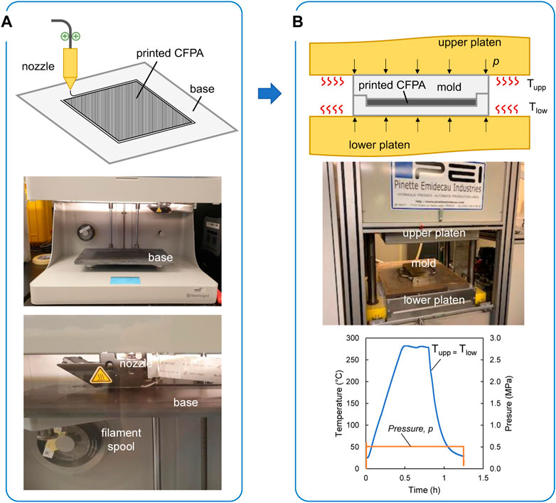
FIGURE 1. (A) 3D printing process of CFPA using fused filament fabrication (FFF) technique; MarkTwo printer (Markforged) and the essential parts (base, nozzle, and filamant spool), (B) post-consolidation process using compression molding technique; the metallic mold used to store the 3D printed laminates is placed between upper and lower platens; temperature and pressure cycles during compression molding process are shown here.
The effectiveness of our proposed method could be affected by the treatment/environment and time gap during the transition period between 3D printing and post-consolidation processes. The polyamide phase in the CFPA is a semicrystalline polymer, which is sensitive to high humidity and time. The polyamide may degrade over time due to moisture via molecular disentanglement mechanism (causing a reduced glass transition temperature (Banjo et al., 2022)), and due to thermal effect (causing volumetric changes (Boisot et al., 2011) or discoloration (Yudhanto et al., 2020)). In our experiments, once the printing process of CFPA laminate was completed, we kept the material in a zipped bag within an acrylic enclosure to provide extra protection from hygrothermal effects. The time gap between the printing and post-consolidation processes was kept minimum, ranging between 30 and 60 min. This time gap was needed to seal the edges of 3D-printed CFPA for leakage mitigation. As we stored the laminate in a controlled environment, the degradation of the mechanical properties of CFPA over time could be minimized.
2.2 Characterization of microscale parameters
The characterization of microscale parameters was performed to identify the physical appearance and volume fractions of filament (before being used for printing), CFPA laminate after printing, and CFPA laminate after the post-consolidation process. The physical appearance was identified by firstly cutting the samples, immersing the samples in the epoxy (EpoFix), and drying the epoxy at room temperature for 24 h. The sample’s cross-section was polished sequentially using sandpaper (TegraPol, Struers) with grit numbers of 500, 1,000, 2,400, and 4,000, and observed using a Leica microscope. The volume fraction of 3D printing filament was calculated based on the optical microscopy images. The volume fraction of fiber, matrix, and void of 3D-printed and post-consolidated CFPA was measured by performing a burn-off test (ASTM D3171-15). The specimen size for burn-off tests was 25 mm × 25 mm × 1.25 mm. The sample density ρs was calculated as ρs = (
2.3 Characterization of mesoscale parameters
The characterization of mesoscale parameters was performed to identify the mechanical properties of matrix-dominated CFPA laminate after printing and after post-consolidation processes. We performed an in-plane shear test on [±45]2s CFPA specimens with dimensions of 125 mm length, 9 mm width, and 1.25 mm thickness. A universal testing machine Instron 5,944 (2 kN load cell) was used to obtain the force and displacement. Shear stress was calculated by dividing the force with 2 × of cross-sectional area (width × thickness). The strain field in x- and y-directions on the specimen surface was measured by digital image correlation (DIC) technique where a bi-telecentric camera (Correlated Solutions) and VIC 2D software were used. A monotonic test was first performed to obtain in-plane shear properties (shear strength τult, failure strain
where
where τmax,i is the maximum shear stress of an i-th cycle. The plasticity is represented by the relationship between plasticity threshold R + R0 and accumulated plastic strain p. The plasticity threshold can be calculated as follows:
where R0 is the yield stress or transition point from linear to non-linear curve in the stress-strain curve. The accumulated strain p is calculated as follows:
where ɛp is the plastic strain.
3 Results and discussion
3.1 Physical features of 3D printing materials
Before the printing process, the physical features of a single filament containing continuous fibers and carbon-filled polyamide matrix (Onyx) were examined using an optical microscope. Figure 2A shows the typical cross-section of a filament where clusters of fibers within the matrix are identified. Six CFPA filaments were analyzed using ImageJ software (Ferreira and Rasband, 2012). The average fiber volume fraction of six filaments was around 18%, which was similar to that reported in another study (Blok et al., 2018) of 20%. However, in terms of filament diameter, our measurement showed that the average diameter was 198 μm, while the average diameter reported in (Blok et al., 2018) was 400 μm. Even though they used the same material, various factors may influence the geometrical differences between our evaluation and those outlined by (Blok et al., 2018), namely, different filament spool specifications, measurement locations, statistical variation, and the number of samples during the measurement. Nonetheless, after the printing process, these differences may diminish as the matrix would likely be melted within the heated nozzle before finally being injected via the fused filament fabrication (FFF). The physical appearance of CFPA laminate is shown in Figure 2B, displaying a neat and smooth printed product. The dimension of this printed CFPA laminate was 250 mm in length and 110 mm in width, which was intentionally made to match the exact size of the post-consolidation mold.
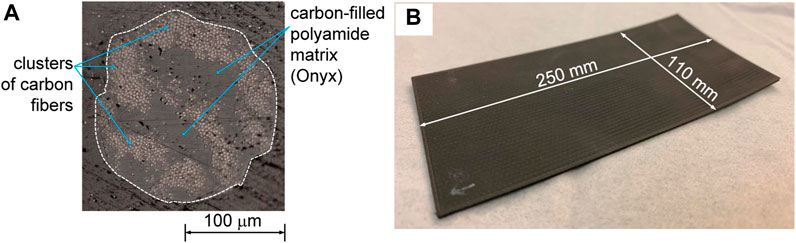
FIGURE 2. (A) Cross-sectional view of a single carbon/Onyx filament (CFPA), (B) 3D printed CFPA laminate made with the exact size for post-consolidation using a metallic mold.
The physical features of 3D printed CFPA might also be affected by the parameters defined during the post-consolidation compression molding process, namely, temperature and time during dwelling, and the cooling rate. At present, the temperature at the dwelling phase was set at a constant temperature of 280°C, making sure that the 3D-printed CFPA was entirely melted. The dwelling time was set at 20 min. Based on our experience in processing semi-crystalline polymers, such as polyamide (Yudhanto et al., 2020) and polypropylene (Wafai et al., 2016; Yudhanto et al., 2016), a 20-min period was deemed sufficient for ensuring a complete melt of 250 mm × 110 mm specimen. The cooling rate that could be achieved by our static press (PEI 15T) was limited to 40°C/min. Indeed, a faster cooling rate utilizing an add-on cooling system would be beneficial to achieve a higher ductility of CFPA.
3.2 Effect of post-consolidation on microscale parameters
The cross-sectional view of 3D-printed and post-consolidated CFPA laminates is shown in Figure 3A. The analysis of the volume fraction of constituents based on the burn-off test is shown in Figure 3B. Here, the fiber volume fraction (Vf) and matrix volume fraction (Vm) of 3D-printed and post-consolidated CFPA laminates are 28.8% and 59.0%, respectively. Our fiber volume fraction measurement was consistent with the one reported in Ref. (Blok et al., 2018), which is 27%. Figure 3A also shows that 3D-printed CFPA laminate exhibited numerous voids that may fall into the category of intra-bead and partial neck growth voids (Tao et al., 2021). The measurement of Vv in the 3D printed CFPA was 12.2%, which was within the range outlined in two other previous studies, 7%–10% in Ref (Blok et al., 2018). and 16.8%–30.8% in Ref. (Lawrence et al., 2022). The voids 3D printed CFPA were believed to be influenced by the deposition angle between two adjacent beads (upper and lower ones). An angle difference of 90° could lead to a lower void content (i.e., better bonding between beads), while the angle difference of 45° could lead to a higher void content (i.e., poorer bonding between beads) (Lawrence et al., 2022). In our experiments, the angle difference in the stacking sequence of [+45/-45]2s was 90°, suggesting that other stacking sequences with lower angle difference, such as [+45/0]s or [+45/90]s, may result in a poorer inter-bead bonding. Figure 3B shows that the proposed post-consolidation process was able to reduce Vv of 3D printed CFPA from 12.2% to 1.8%. Consequently, Vm of the post-consolidated CFPA was increased to 68.0%. On the other hand, the fiber volume fraction remains unaffected by the post-consolidation process due to the better integrity of continuous carbon fibers during the melting process. It is thus evident that our post-consolidation process was beneficial in the reduction of voids, enabling better microstructural quality.
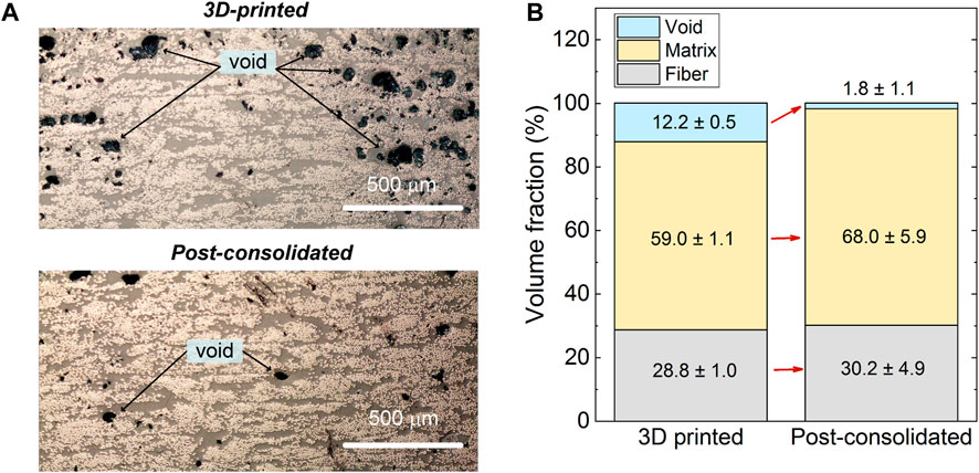
FIGURE 3. (A) Cross-sectional view of microstructure of 3D printed and post-consolidated CFPA; (B) volume fraction of fiber, matrix, and void of CFPA after 3D printing and post-consolidation processes.
3.3 Effect of post-consolidation on the mesoscale parameters
At the mesoscale level, the post-consolidation process modified the in-plane shear properties of [±45]2s (matrix-dominated lay-up). Figure 4 shows that the stress-strain (τxy-γxy) curves of 3D-printed and post-consolidation CFPA. Table 1 summarizes the in-plane shear properties derived from the stress-strain curves. Here, the post-consolidation process was able to improve
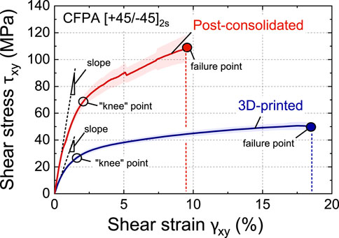
FIGURE 4. Shear stress and shear strain of CFPA laminates obtained from monotonic tensile test of [±45]2s lay-up. The slope made on the linear dashed line corresponds to the shear modulus
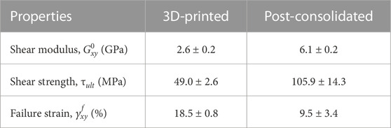
TABLE 1. Elastic properties of CFPA laminates measured from monotonic in-plane shear test.
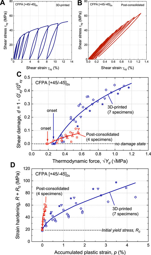
FIGURE 5. Cyclic in-plane shear test results: stress-strain curves of (A) 3D printed CFPA, (B) post-consolidated CFPA; (C) damage master curve; (D) plasticity master curve.
4 Conclusion
The present study investigated effect of the post-consolidation process using classical compression molding on the microscale and mesoscale parameters of 3D-printed continuous carbon fiber-reinforced polyamide (CFPA). We found that the proposed post-consolidation step was able to reduce the microscale parameter, namely, void content, of the 3D-printed CFPA, achieving a value of below 2%. The effect of the post-consolidation process on the mesoscale parameters was investigated by performing mechanical tests on matrix-dominated lay-up. Here, the shear modulus and shear strength of 3D-printed CFPA laminate were improved by 100%–140%. In addition, the mesoscale damage analysis shows that the post-consolidated CFPA exhibited reduced strain hardening, and better damage resistance, improving the potential for load-bearing structures.
Data availability statement
The raw data supporting the conclusion of this article will be made available by the authors, without undue reservation.
Author contributions
AY: Conceptualization, Formal Analysis, Investigation, Methodology, Writing–original draft, Writing–review and editing. AA: Data curation, Investigation, Writing–original draft. EF: Conceptualization, Funding acquisition, Resources, Supervision, Writing–review and editing. GL: Conceptualization, Formal Analysis, Funding acquisition, Resources, Supervision, Writing–review and editing.
Funding
The author(s) declare that financial support was received for the research, authorship, and/or publication of this article. We thank King Abdullah University of Science and Technology (KAUST) for providing research funding (award number BAS/1/1315-01-01).
Acknowledgments
We would like to thank Mr. Kuat Telegenov of the Robotics, Intelligent Systems and Control Laboratory, Computer, Electrical, and Mathematical Science (CEMSE) Division at King Abdullah University of Science and Technology (KAUST) for supporting the 3D printing process, and Dr. Walid Abediseid (KAUST Young Talent Development, Strategic National Advancement).
Conflict of interest
The authors declare that the research was conducted in the absence of any commercial or financial relationships that could be construed as a potential conflict of interest.
Publisher’s note
All claims expressed in this article are solely those of the authors and do not necessarily represent those of their affiliated organizations, or those of the publisher, the editors and the reviewers. Any product that may be evaluated in this article, or claim that may be made by its manufacturer, is not guaranteed or endorsed by the publisher.
References
Banjo, A. D., Agrawal, V., Auad, M. L., and Celestine, A.-D. N. (2022). Moisture-induced changes in the mechanical behavior of 3d printed polymers. Compos. Part C. Open Access 7, 100243. doi:10.1016/j.jcomc.2022.100243
Blok, L. G., Longana, M. L., Yu, H., and Woods, B. K. (2018). An investigation into 3D printing of fibre reinforced thermoplastic composites. Addit. Manuf. 22, 176–186. doi:10.1016/j.addma.2018.04.039
Boisot, G., Laiarinandrasana, L., Besson, J., Fond, C., and Hochstetter, G. (2011). Experimental investigations and modeling of volume change induced by void growth in polyamide 11. Int. J. Solids Struct. 48, 2642–2654. doi:10.1016/j.ijsolstr.2011.05.016
Brenken, B., Barocio, E., Favaloro, A., Kunc, V., and Pipes, R. B. (2018). Fused filament fabrication of fiber-reinforced polymers: a review. Addit. Manuf. 21, 1–16. doi:10.1016/j.addma.2018.01.002
Dilberoglu, U. M., Gharehpapagh, B., Yaman, U., and Dolen, M. (2017). “The role of additive manufacturing in the era of industry 4.0,” in 27th International Conference on Flexible Automation and Intelligent Manufacturing, FAIM2017, 27-30 June 2017. Elsevier: (Modena, Italy), Procedia Manuf., 545–554. doi:10.1016/j.promfg.2017.07.148
Duda, T., and Raghavan, L. V. (2016). “3d metal printing technology,” in 17th IFAC Conference on International Stability, 103–110. Technology and Culture TECIS 2016, IFAC-Papers OnLine. doi:10.1016/j.ifacol.2016.11.111
Elkington, M., Bloom, D., Ward, C., Chatzimichali, A., and Potter, K. (2015). Hand layup: understanding the manual process. Adv. Manuf. Polym. Compos. Sci. 1, 138–151. doi:10.1080/20550340.2015.1114801
Ferreira, T., and Rasband, W. (2012). Imagej user guide ij 1.46r . USA: National Institutes of Health.
Harris, C. G., Jursik, N. J. S., Rochefort, W. E., and Walker, T. W. (2019). Additive manufacturing with soft tpu – adhesion strength in multimaterial flexible joints. Front. Mech. Eng. 5. doi:10.3389/fmech.2019.00037
He, Q., Wang, H., Fu, K., and Ye, L. (2020). 3d printed continuous cf/pa6 composites: effect of microscopic voids on mechanical performance. Compos. Sci. Technol. 191, 108077. doi:10.1016/j.compscitech.2020.108077
Ichihara, N., Ueda, M., Urushiyama, Y., Todoroki, A., Matsuzaki, R., and Hirano, H. (2020). Progressive damage simulation for a 3D-printed curvilinear continuous carbon fiber-reinforced thermoplastic based on continuum damage mechanics. Adv. Compos. Mater. 29, 459–474. doi:10.1080/09243046.2020.1724430
Ladeveze, P., and Dantec, E. L. (1992). Damage modelling of the elementary ply for laminated composites. Compos. Sci. Technol. 43, 257–267. doi:10.1016/0266-3538(92)90097-m
Lawrence, B. D., Coatney, M. D., Phillips, F., Henry, T. C., Nikishkov, Y., and Makeev, A. (2022). Evaluation of the mechanical properties and performance cost of additively manufactured continuous glass and carbon fiber composites. Int. J. Adv. Manuf. Technol. 120, 1135–1147. doi:10.1007/s00170-022-08879-w
Lee, G.-W., Kim, T.-H., Yun, J.-H., Kim, N.-J., Ahn, K.-H., and Kang, M.-S. (2023). Strength of onyx-based composite 3d printing materials according to fiber reinforcement. Front. Mater. 10. doi:10.3389/fmats.2023.1183816
Maassarani, B., Epps, J., Garanger, K., Shahab, M. T., Wali, O., and Feron, E. (2023). Unmanned aerial vehicles applications: challenges and trends . Springer. chap. Tetrahedral and Dodecahedral UASs, Structured Designs.
McIlhagger, A., Archer, E., and McIlhagger, R. (2020). “3 - manufacturing processes for composite materials and components for aerospace applications,” in Polymer composites in the aerospace industry. Woodhead publishing series in composites science and engineering . Editors P. Irving, and C. SoutisSecond edition edn. Woodhead Publishing: (Woodhead Publishing), 59–81. doi:10.1016/B978-0-08-102679-3.00003-4
Mei, H., Ali, Z., Yan, Y., Ali, I., and Cheng, L. (2019). Influence of mixed isotropic fiber angles and hot press on the mechanical properties of 3D printed composites. Addit. Manuf. 27, 150–158. doi:10.1016/j.addma.2019.03.008
Mohammadizadeh, M., Imeri, A., Fidan, I., and Elkelany, M. (2019). 3d printed fiber reinforced polymer composites - structural analysis. Compos. Part B Eng. 175, 107112. doi:10.1016/j.compositesb.2019.107112
Panwisawas, C., Tang, Y. T., and Reed, R. C. (2020). Metal 3d printing as a disruptive technology for superalloys. Nat. Commun. 11, 1–4. doi:10.1038/s41467-020-16188-7
Parker, M., Inthavong, A., Law, E., Waddell, S., Ezeokeke, N., Matsuzaki, R., et al. (2022). 3d printing of continuous carbon fiber reinforced polyphenylene sulfide: exploring printability and importance of fiber volume fraction. Addit. Manuf. 54, 102763. doi:10.1016/j.addma.2022.102763
Polyzos, E., Katalagarianakis, A., Hemelrijck, D. V., and Pyl, L. (2021). Delamination analysis of 3D-printed nylon reinforced with continuous carbon fibers. Addit. Manuf. 46, 102144. doi:10.1016/j.addma.2021.102144
Pourali, M., and Peterson, A. M. (2022). A tale of two polyamides: comparing the crystallization kinetics of a hot-melt adhesive and a pa 6/66 copolymer. Thermochim. Acta 710, 179176. doi:10.1016/j.tca.2022.179176
Sarfraz, M. S., Hong, H., and Kim, S. S. (2021). Recent developments in the manufacturing technologies of composite components and their cost-effectiveness in the automotive industry: a review study. Compos. Struct. 266, 113864. doi:10.1016/j.compstruct.2021.113864
Sayah, N., and Smith, D. E. (2022). Effect of process parameters on void distribution, volume fraction, and sphericity within the bead microstructure of large-area additive manufacturing polymer composites. Polymers 14, 5107. doi:10.3390/polym14235107
Soutis, C. (2005). Fibre reinforced composites in aircraft construction. Prog. Aerosp. Sci. 41, 143–151. doi:10.1016/j.paerosci.2005.02.004
Tao, Y., Kong, F., Li, Z., Zhang, J., Zhao, X., Yin, Q., et al. (2021). A review on voids of 3d printed parts by fused filament fabrication. J. Mater. Res. Technol. 15, 4860–4879. doi:10.1016/j.jmrt.2021.10.108
Thomas, L., and Ramachandra, M. (2018). “Advanced materials for wind turbine blade-a review,” in International Conference on Advanced Materials and Applications (ICAMA 2016), Bengaluru, Karanataka, INDIA, June 15-17, 2016, 2635–2640. Materials Today: Proceedings 5. doi:10.1016/j.matpr.2018.01.043
Todoroki, A., Oasada, T., Mizutani, Y., Suzuki, Y., Ueda, M., Matsuzaki, R., et al. (2020). Tensile property evaluations of 3D printed continuous carbon fiber reinforced thermoplastic composites. Adv. Compos. Mater. 29, 147–162. doi:10.1080/09243046.2019.1650323
Wafai, H., Lubineau, G., Yudhanto, A., Mulle, M., Schijve, W., and Verghese, N. (2016). Effects of the cooling rate on the shear behavior of continuous glass fiber/impact polypropylene composites (GF-IPP). Compos. Part A 91, 41–52. doi:10.1016/j.compositesa.2016.09.014
Yudhanto, A., Almulhim, M., Kamal, F., Tao, R., Fatta, L., Alfano, M., et al. (2020). Enhancement of fracture toughness in secondary bonded cfrp using hybrid thermoplastic/thermoset bondline architecture. Compos. Sci. Technol. 199, 108346. doi:10.1016/j.compscitech.2020.108346
Yudhanto, A., Lubineau, G., Wafai, H., Mulle, M., Pulungan, D., Yaldiz, R., et al. (2016). Monotonic and cyclic responses of impact polypropylene and continuous glass fiber-reinforced impact polypropylene composites at different strain rates. Polym. Test. 51, 93–100. doi:10.1016/j.polymertesting.2016.03.008
Keywords: 3D printing, composites, damage, plasticity, void, carbon fiber, manufacturing
Citation: Yudhanto A, Aldhirgham A, Feron E and Lubineau G (2023) Post-consolidation process for modifying microscale and mesoscale parameters of 3D printed composite materials. Front. Mater. 10:1286840. doi: 10.3389/fmats.2023.1286840
Received: 31 August 2023; Accepted: 06 November 2023;
Published: 22 November 2023.
Edited by:
Nicola Maria Pugno, University of Trento, ItalyReviewed by:
Roberto Fedele, Polytechnic University of Milan, ItalyKailu Xiao, Texas A and M University, United States
Copyright © 2023 Yudhanto, Aldhirgham, Feron and Lubineau. This is an open-access article distributed under the terms of the Creative Commons Attribution License (CC BY). The use, distribution or reproduction in other forums is permitted, provided the original author(s) and the copyright owner(s) are credited and that the original publication in this journal is cited, in accordance with accepted academic practice. No use, distribution or reproduction is permitted which does not comply with these terms.
*Correspondence: Arief Yudhanto, yudhantoa@gmail.com, Arief_Yudhanto@baylor.edu