Structural design and performance study of permanent magnet safety coupling based on magnetorheological transmission technology
 Huirong Zhang
 Qinghua Song
 Zhongfu Yao3
  Zeyang Cai
- 1College of Mechanical and Electronic Engineering, Shandong Agriculture and Engineering University, Jinan, China
- 2College of Mechanical Engineering, Shandong University, Jinan, China
- 3Department of Intelligent Manufacturing, Shandong Labor Vocational and Technical College, Jinan, China
Based on magnetorheological transmission technology, a design for a permanent magnet safety coupling is proposed. Firstly, the structure scheme of the coupling is designed in detail, and its working principle and process are explained; Additionally, the influence of coupling structural parameters on magnetic field strength is studied by ANSYS, and the coupling’s structural parameters are optimized; Finally, the prototype of the permanent magnet magnetorheological fluid coupling is tested for no-load characteristics and torque regulation characteristics through the preparation of magnetorheological fluid (MRF) and the construction of an experimental platform, the experimental results demonstrated that the prototype effectively transmits torque, and the no-load torque increases as the speed increases, at a motor speed of 400 r/min, the experimental prototype achieves a maximum no-load torque of 2.6 N.m; Under specific conditions of magnetic field strength and volume ratio, the torque transmitted by the coupling increases with the volume, for instance, when the volume of MRF is 50 mL and a motor speed of 600 r/min, the experimental prototype achieves a maximum torque value of 8.7 N.m, additionally, when the volume is constant, the torque transmitted by the experimental prototype remains basically unchanged with the change of slip speed, showing the characteristic of constant torque, this study offers theoretical and practical insights for the design and experimental analysis of similar products.
1 Introduction
MRF is a widely researched smart material comprised of micrometer-sized ferromagnetic particles, a base load fluid capable of suspending these particles, and an additive that prevents their settling (Rabinow, 1948; Chen et al., 2013). In the absence of a magnetic field, magnetorheological fluids (MRFs) exhibit the properties of low viscosity Newtonian liquids. However, when a magnetic field is applied, the viscosity of these fluids undergoes a substantial change. Within milliseconds, the state of MRFs transitions from a liquid to a solid-like state. Furthermore, the yield stress of these fluids significantly increases with the strengthening of the magnetic field (Huang et al., 2022). MRF has such good Magnetorheological (Mr) Characteristics, which makes them play a very important role in magnetorheological drive technology, especially in the coupling, clutch, brake (Rizzo et al., 2015) has a large application space, in recent years, many patents on Mr Clutch and brake have been authorized (Gopalswamy et al., 1998; Patrick et al., 2001), these authorized clutches and brakes have the structure of flat disk type, U type and so on, and most of them are excited by coil, coil excitation has complex structure, energy consumption and other problems; There are few studies on permanent magnet as a magnetic field excitation source. Bucchi et al. (2014) designed a permanent magnet excitation type clutch and carried out theoretical analysis and experimental tests on the clutch. Chen. (2021) designed a new type of Mr Safety coupling and conducted simulation analysis on the internal magnetic field of the coupling, and obtained the simulation results of the force transmission characteristics of the safety coupling. Wang et al. (2023) designed a safety clutch device, which relates to the field of agricultural machinery harvesting. Based on the aforementioned research, the author suggests a structural scheme for a permanent magnet safety coupling based on Mr Transmission technology, this coupling does not require external energy and offers advantages such as a simple structure, safety, reliability, and overload protection. The experimental testing focused on the permanent magnet Magnetorheological fluid coupling prototype, specifically examining its no-load characteristics and torque regulation characteristics.
2 Structural design of permanent magnet magnetorheological fluid coupling
The structure of the permanent magnet magnetorheological fluid coupling is shown in Figure 1, which mainly consists of an active rotor component and a driven rotor component. Figure 1A shows the axial section structure of the permanent magnet magnetorheological fluid coupling. The active rotor component is composed of the drive shaft 1, the active rotor 2, seal the plug 3, the magnetic barrier ring 4, the permanent magnet 5 and magnetic insulation tile 11, and the driven rotor component is composed of the driven rotor 6 and the driven shaft 7. The end cover 9 combines the active rotor component and the driven rotor component into a closed cavity 12 through a sealing ring 8 and a screw 10. The cavity 12 is used as a storage space for the MRF.
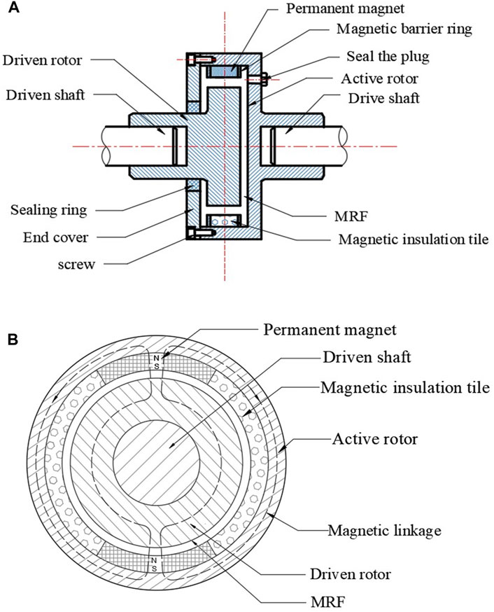
FIGURE 1. The structure of the permanent magnet magnetorheological fluid coupling. (A) the axial section structure of the permanent magnet magnetorheological fluid coupling, (B) the end-view structure of the permanent magnet magnetorheological fluid coupling.
In Figure 1B, the end-view structure of the permanent magnet magnetorheological fluid coupling is depicted. Permanent magnet 5 and magnetic insulation tile 11 are distributed on the inner surface of the circumference of the active rotor 2, alternately arranged. The shape of permanent magnet is tile-shaped, radially magnetized, and the magnetic poles of adjacent permanent magnets are opposite. During operation, the permanent magnet generates a magnetic field, which magnetizes the magnetic particles present in the MRF, this results in the formation of a magnetic linkage 13 along the direction of the magnetic field, connecting the components in the following sequence: permanent magnet 5→active rotor 2→ permanent magnet 5→ MRF in cavity 12 → driven rotor 6→ MRF in cavity 12 → permanent magnet 5, this magnetic linkage significantly enhances the shear yield stress of the MRF. As the motor rotates, the drive shaft 1 drives the active rotor 2 to rotate, through the MRF, the rotation of the active rotor 2 synchronously drives the driven rotor 6 and the driven shaft 7, enabling the coupling to perform its intended function.
In order to achieve vertical passage of magnetic field lines through the working gap, the drive shaft and driven shaft are constructed using 45 steel, known for its favorable mechanical properties. Likewise, the active rotor and the driven rotor are made from Q235 carbon structural steel, which possesses high permeability. To ensure radial passage of magnetic field lines through the MRF in cavity 12, and to prevent magnetic short circuiting, the magnetic insulation tile and magnetic barrier ring are fabricated from aluminum alloy 6061, known for its low permeability. Additionally, NdFeB is selected as the permanent magnet material, the grade of which is N35EH, MRF used in this experiment is self-prepared.
3 Preparation and characteristics measurement of MRF
3.1 Preparation of MRF
The excellent performance of MRF is the key to the smooth conduct of the experiment, the MRF used in this experiment is self-prepared. In the experiment, the carbonyl iron powder of MPS-MRF-35 was selected as magnetic particles, the base loading fluid was selected as dimethylsilicone oil, and the surface additive was selected as sodium dodecyl sulfate as the raw material for the preparation of MRF, and the magnetorheological fluid with an integral number of carbonyl iron powder of 25% was prepared, the carbonyl iron powder, dimethylsilicone oil and sodium dodecyl sulfate were weighed according to the calculated ratio. The specific preparation process (Zhu et al., 2019) is illustrated in Figure 2.
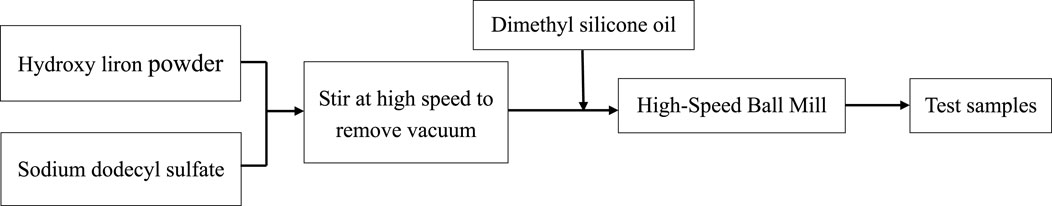
FIGURE 2. MRF preparation flow chart.
3.2 Measurement of the characteristics of MRF
3.2.1 Determination of the relationship curve between yield stress and magnetic field variation
The testing instrument used in this experiment was the Anton Paar MCR302 Rheometer. The measurement method involves setting the test temperature at 40°C, during the test, the spacing value of the parallel plate test system was a fixed value, the parallel plates were filled with the MRF samples to be tested, and a constant shear rate of 10s-1 was applied, the varying magnetic field of 0∼1T was applied to determine the relationship curve between the yield stress of the MRF and the change in magnetic field, as shown in Figure 3.
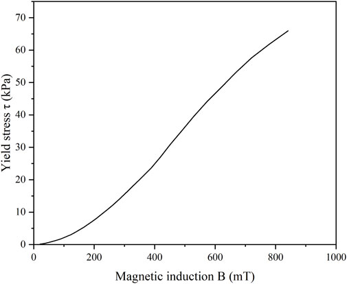
FIGURE 3. Curve of relation between yield stress and magnetic induction.
3.2.2 Measurement of B-H curve
The B-H curve was measured by filling MRF into a closed test tube with a diameter of 1 mm and a height of 2 mm, at room temperature, the relationship between the change of the applied magnetic field intensity H and magnetic induction B was measured with a vibrating sample magnetometer (model Lake shore 7410) as shown in Figure 4.
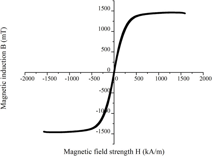
FIGURE 4. B-H curve of MRF.
4 Influence of coupling structural parameters on magnetic field strength
4.1 Influence of rotor thickness on magnetic field strength
To analyze the influence of rotor thickness on magnetic field strength, the following structural parameters are initially set up: The outer diameter of the active rotor is φ119 mm, the thickness of the permanent magnet is 6mm, and the working gap of MRF is 1.5 mm, the thickness of the active rotor is designed to be 2mm, 4mm, 6mm, 8mm and 10 mm successively, the influence of the thickness of the active rotor on the magnetic induction intensity is analyzed, and the results are shown in Figure 5. Figure 5 shows that magnetic induction intensity B increases with the increase of rotor thickness within a certain range. However, when the thickness of the active rotor exceeds 8mm, the value of magnetic induction intensity B remains relatively unchanged. Therefore, it is appropriate to optimize the thickness of the active rotor as 8 mm.
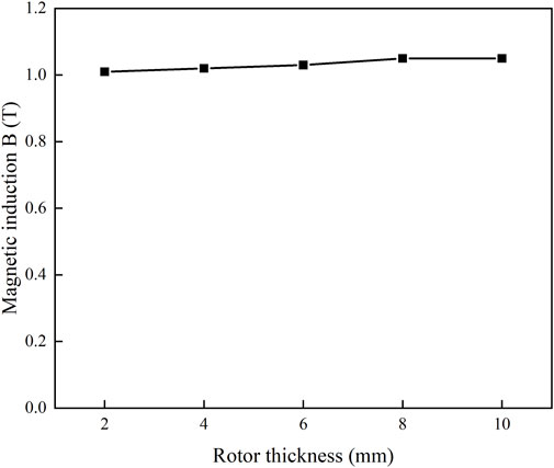
FIGURE 5. Influence curve of rotor thickness on magnetic field strength.
4.2 Influence of permanent magnet thickness on magnetic field strength
To analyze the influence of permanent magnet thickness on magnetic field strength, the following structural parameters are initially set up: The outer diameter of the active rotor is φ119 mm, the inner diameter of the active rotor is φ103mm, the working gap of MRF is 1.5 mm, and the thickness of the permanent magnet is designed to be 2mm, 4mm, 6mm, 8mm and 10 mm successively, the influence of the thickness of the permanent magnet on the magnetic induction intensity is analyzed, and the results are shown in Figure 6. Figure 6 shows that when the thickness of the permanent magnet is less than 6 mm, the magnetic induction intensity B increases with the increase of the thickness of the permanent magnet, when the thickness of the rotor permanent magnet is 6mm, the magnetic induction intensity B reaches the maximum value. However, when the thickness of the permanent magnet exceeds 6mm, the magnetic induction intensity B decreases, therefore, it is appropriate to optimize the thickness of the permanent magnet as 6 mm.
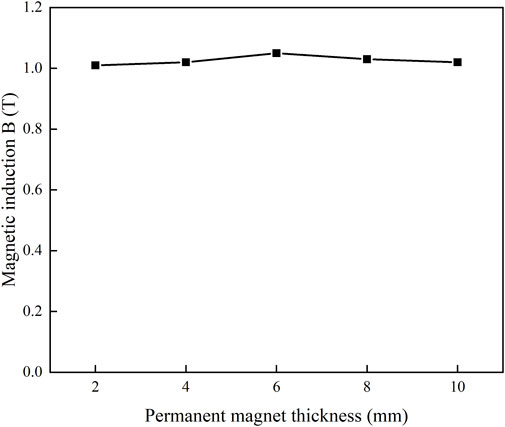
FIGURE 6. The influence curve of permanent magnet thickness on magnetic field strength.
4.3 Influence of working gap on magnetic field strength
To analyze the influence of working gap on magnetic field strength, the following structural parameters are initially set up: The outer diameter of the active rotor is φ119 mm, the inner diameter of the active rotor is φ103 mm, the thickness of the permanent magnet is 6 mm, the working gap of MRF is designed to be 1mm, 1.5mm, 2mm, 2.5 mm successively, to analyze the influence of working gap on magnetic induction strength, and the results are shown in Figure 7. Figure 7 shows that with the increase of working gap, the value of magnetic induction intensity B decreases continuously, in order to ensure its normal working performance and take into account the manufacturing cost of the permanent magnet magnetorheological fluid coupling, the working gap should be 1.5∼2 mm.
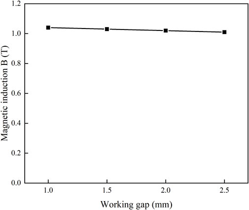
FIGURE 7. The influence curve of working gap on magnetic field strength.
To reduce the occurrence of magnetic leakage and other phenomena, the thickness of the magnetic insulation tile should generally be greater than or equal to the thickness of the permanent magnet (Kong et al., 2006), the thickness of the magnetic insulation tile designed is 6 mm in this paper. By analyzing the influence of structural parameters such as rotor thickness, permanent magnet thickness and working gap on magnetic field strength B, the structural parameter values of the permanent magnet magneorheological fluid coupling are selected, as shown in Table 1, and the assembly of the coupling was completed, the physical object of the permanent magnet magnetorheological fluid coupling is shown in Figure 8.
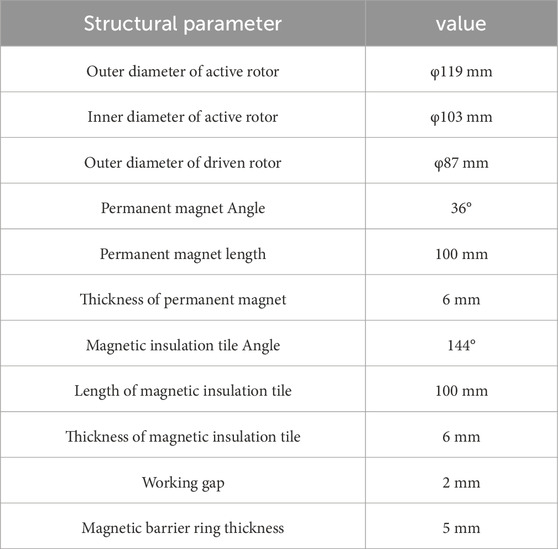
TABLE 1. Coupling structure parameters.
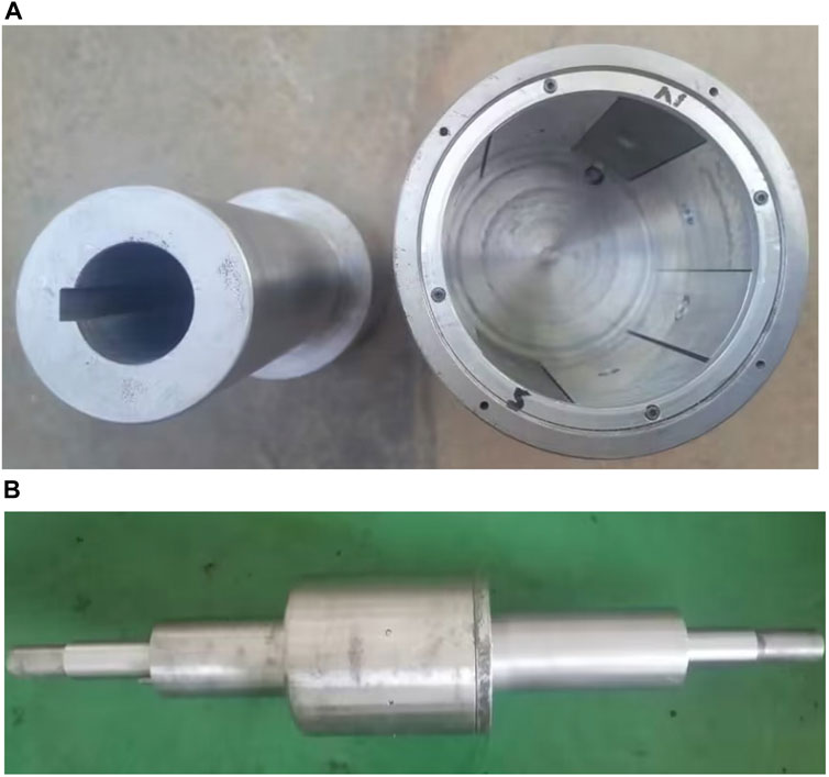
FIGURE 8. Physical diagram of permanent magnet magnetorheological fluid coupling. (A) Physical components of the main and slave rotor, (B) Coupling assembly drawing.
5 Magnetic field finite element analysis
5.1 Material definition
During the magnetic field simulation, Q235 with high permeability is selected for the rotor, and the material properties are shown in Figure 9. Aluminum alloy 6061 with low permeability is selected as the magnetic insulation tile, and the relative permeability is 1. The magnetorheological fluid is prepared by itself, and the material properties are shown in Figures 3, 4. The permanent magnet material is N35EH, and its main physical characteristics (Su et al., 2012)include remanence
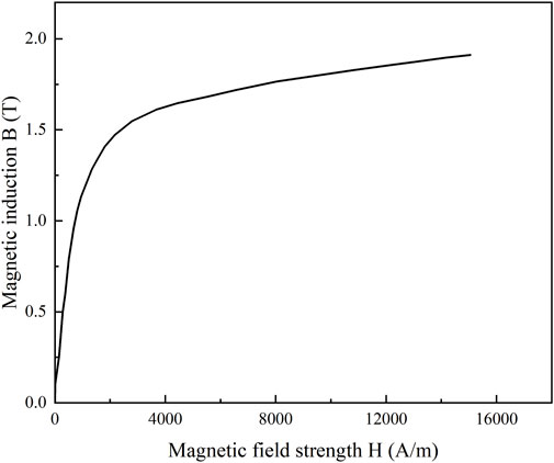
FIGURE 9. B-H curve of Q235.
5.2 Results of finite element analysis
ANSYS was used to analyze the static magnetic field of the selected coupling structure parameters, and the magnetic field line trend is shown in Figure 10A and the magnetic flux density vector trend is shown in Figure 10B, the simulation results show that the magnetic field line and magnetic flux density trend are consistent with the theoretical design. Working gap magnetic density amplitude results are shown in Figure 10C, the simulation results show that the maximum magnetic density between active rotor and driven rotor is 1.051T, the maximum amplitude of the gap magnetic density is distributed in the two angles of 70–110° and 250–290° in the circumferential direction of the permanent magnet (the horizontal direction to the right is set to 0°), which is similar to the theoretical design.
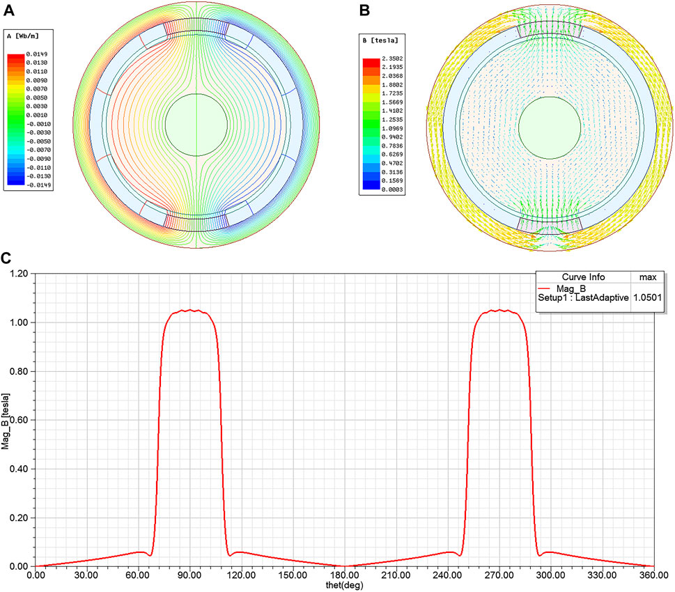
FIGURE 10. Simulation results. (A) magnetic field line distribution diagram, (B) magnetic flux density vector, (C) gap magnetic density amplitude distribution diagram.
6 Experimental verification
6.1 Experimental platform construction
To verify the rationality of structural design and the correctness of simulation results, an laboratory table for testing the performance of permanent magnet magnetorheological fluid coupling is set up. The laboratory table is mainly composed of mechanical transmission system, detection system and control system (Li, 2019). The experimental block diagram is shown in Figure 11, and the experimental device diagram is shown in Figure 12, in which Figure 12A is the actual assembly diagram of the laboratory table.
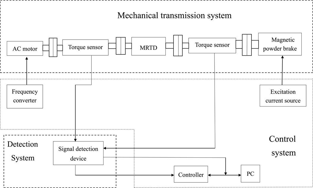
FIGURE 11. Experimental block diagram.
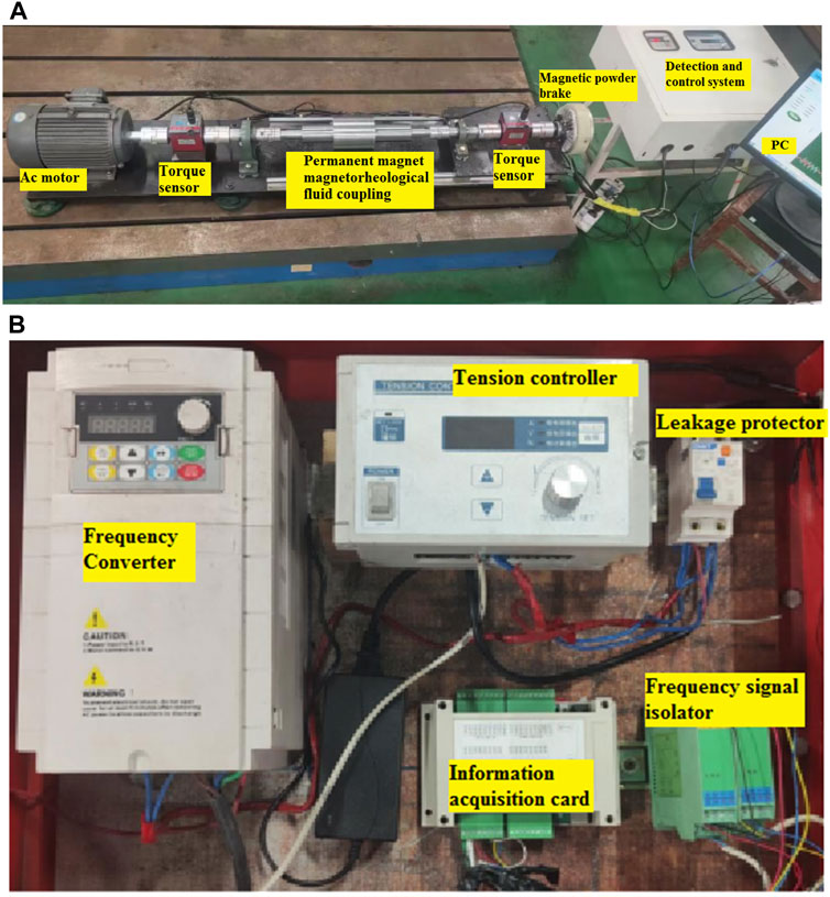
FIGURE 12. Experimental installation drawing. (A) Physical drawings of the experimental bench assembly, (B) Part of the test system and control system.
The mechanical transmission system consists of several components such as a three-phase AC motor, permanent magnet magnetorheological fluid coupling, torque sensor, and magnetic powder brake. Its primary purpose is to facilitate power transmission and conduct transmission characteristic tests on the permanent magnet magnetorheological fluid coupling (Tian, 2012). The three-phase AC motor used in the system is the YX3-100L-4 model, with a rated power of 3 kW and a rated speed of 1400 r/min; The torque sensor employed is the HPT-151 model, capable of measuring a maximum driving torque of 100 N.m; The magnetic powder brake utilized is the FZ25-1 model, with a rated torque of 20 Nm, a maximum current of 1.5A, and a rated speed of 1400 r/min.
The detection and control system are integrated in a single installation and connection box, as shown in Figure 12B. The detection system includes a signal detection device that is directly connected to the sensor, this device records the torque and speed signals collected by the torque sensor and displays them on the upper computer. On the other hand, the control system consists of a frequency converter and a tension controller, these components are responsible for controlling the variables in the experiment. The frequency converter adjusts the motor speed to test the effect of different speeds on the performance of the permanent magnet magnetorheological fluid coupling, meanwhile, the tension controller controls the load provided by the magnetic powder brake on the entire transmission system, the speed change of the permanent magnet magnetorheological fluid coupling is measured by adjusting the braking torque. The specific models and specifications of the frequency inverter and the tension controller are as follows: the frequency inverter model is G5M-1.5T4-1A, with a speed range of 0-1440r/min; the tension controller model is FZ-A-25, with a control accuracy of 0.01A.
6.2 Experimental test and result analysis
6.2.1 No-load characteristic test
No-load characteristics mainly test the ability of the coupling to transmit torque without MRF. The method is to brake the output end through the magnetic powder brake, and test the relationship between the output torque of Mr Fluid coupling and the speed of the motor. The sensor and acquisition card were used to record the results, and the sampling speed was set to 25 s, the acquisition results were shown in Figure 13, as can be seen from Figure 13, no-load torque also increases with the increase of speed, when the speed is 125 r/min, the no-load torque is 1.5 N.m, and the speed is 400 r/min, the no-load torque reaches the maximum value of 2.6 N.m. Under normal circumstances, no-load torque is mainly caused by factors such as the friction of the components inside the device and the external rotor, and the smaller the test result, the smaller the friction torque, the experimental results show that the experimental prototype has a low no-load torque, which meets the design requirements (Chen and Zheng, 2020).
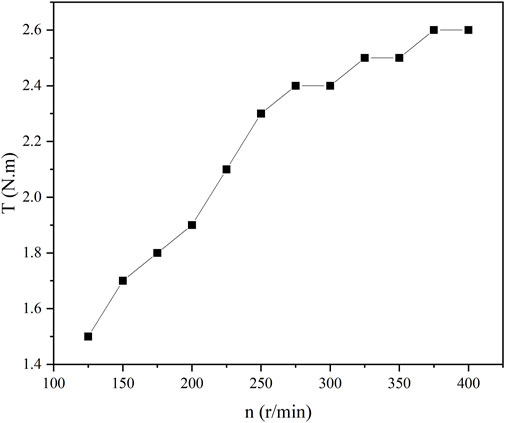
FIGURE 13. No-load characteristic curve.
6.2.2 Torque regulation characteristic test
The torque regulation characteristics refer to the variation law of the transmitted torque of the permanent magnet magneorheological fluid coupling under the condition of different slip speed when the magnetic field is kept constant, the test method of the moment adjustment characteristic is to adjust the magnetic powder brake so that the output end is fixed, adjust the input speed by changing the frequency of the inverter to obtain different slip speed, and observe the change law of the transmitted torque under different slip speed. The slip speed increment is set to 20 r/min, and the motor speed variation range is 400 r/min-600 r/min, the experimental parameters are collected using the sensor and acquisition card, and the torque adjustment characteristic curve is drawn with the experimental data, as shown in Figure 14. As can be seen from Figure 14: when the magnetic field strength and volume ratio (=25%) remain unchanged, the volume of MRF is 30mL, and the transmission torque of the coupling increases slightly with the increase of the slip speed, until the speed is 600 r/min, and the maximum is 7.2 N.m; When the maximum volume of MRF is 50 mL, the transmission torque of the coupling increases slightly with the increase of the slip speed, until the speed is 600r/min, and the maximum is 8.7 N.m; The experimental results show that the larger MRF volume is, the larger the transmitted torque is under the condition of a fixed magnetic field intensity and volume ratio; When the volume is constant, the transmitted torque increases slightly with the increase of the slip speed and basically remains unchanged, which is the outstanding advantage of the permanent magnet Mr Fluid coupling, when the load suddenly increases or is subjected to external impact, the torque transmitted by the permanent magnet Mr Fluid coupling exceeds the limit working torque that MRF can achieve, and the active and driven rotors of the coupling will slip, thus, it can protect the working equipment against overload (Lv, 2011).
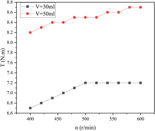
FIGURE 14. Characteristic curve of moment adjustment.
7 Conclusion
Based on magnetorheological transmission technology, an experimental prototype of a permanent magnet safety coupling was designed. The prototype was tested on a built experimental bench to evaluate its no-load characteristics and torque regulation characteristics. Based on the results of the tests, the following conclusions were drawn:
(1) A permanent magnet magnetorheological fluid safety coupling was designed. Its working principle and working process were explained, and the magnetic field finite element analysis was carried out. The simulation results confirmed that the trend of the magnetic field lines and magnetic flux density aligned with the theoretical design. Additionally, the maximum magnetic density between active rotor and driven rotor is 1.051 T, the maximum amplitude of the gap magnetic density is distributed in the two angles of 70–110° and 250–290° in the circumferential direction of the permanent magnet (the horizontal direction to the right is set to 0°), which is similar to the theoretical design.
(2) The experimental results of no-load characteristics show that the experimental prototype can effectively transmit torque, and the no-load torque increases with the increase of the speed. When the motor speed is 400r/min, the no-load torque of the coupling reaches the maximum value of 2.6 N.m.
(3) The experimental results of torque regulation characteristics show that when the magnetic field strength is constant and the volume ratio is constant, the larger the volume, the larger the torque transmitted by the coupling will be, when the volume of MRF is 50 mL and the motor speed is 600r/min, the maximum torque value of 8.7 N.m is reached; When the volume is constant, the torque transmitted by the experimental prototype basically remains unchanged with the change of slip speed, showing the characteristics of constant torque. When the load suddenly increases or external shocks occur, the torque transmitted by the coupling exceeds the maximum working torque that can be achieved by the MRF, and the coupling will slip and play the role of overload protection.
Data availability statement
The datasets presented in this study can be found in online repositories. The names of the repository/repositories and accession number(s) can be found in the article/Supplementary material.
Author contributions
HZ: Funding acquisition, Methodology, Software, Validation, Writing–original draft, Writing–review and editing. QS: Conceptualization, Methodology, Writing–original draft, Writing–review and editing. ZY: Conceptualization, Software, Methodology, Writing–review and editing. JW: Resources, Supervision, Writing–review and editing. ZC: Investigation, Validation, Writing–review and editing.
Funding
The author(s) declare financial support was received for the research, authorship, and/or publication of this article. This research was supported by Agricultural Major Application Technology Innovation Project of Shandong Province (SD2019NJ011), Shandong Agriculture and Engineering University Young Teachers Research Project (QNKZY201908).
Conflict of interest
The authors declare that the research was conducted in the absence of any commercial or financial relationships that could be construed as a potential conflict of interest.
Publisher’s note
All claims expressed in this article are solely those of the authors and do not necessarily represent those of their affiliated organizations, or those of the publisher, the editors and the reviewers. Any product that may be evaluated in this article, or claim that may be made by its manufacturer, is not guaranteed or endorsed by the publisher.
References
Bucchi, F., Forte, P., Frendo, F., Musolino, A., and Rizzo, R. (2014). A fail-safe magnetorheological clutch excited by permanent magnets for the disengagement of automotive auxiliaries. J.Journal intelligent material Syst. Struct. 25 (16), 2102–2114. doi:10.1177/1045389X13517313
Chen, K. F., and Zheng, X. P. (2020). Design and performance experiment of a new magnetorheological braking device for traction elevator. J.Journal Vib. Shock 39 (23), 165–175. doi:10.13465/j.carolcarrollnki.JVS.2020.23.025
Chen, W. (2021). Numerical Simulation and Analysis of Physical field of Magnetorheological safety coupling under permanent magnet excitation. J. Chin. J. Appl. Mech. 201,38 (01), 434–440.
Chen, X., Zhu, X. Q., Ze, Y. X., Lin, Y. C., and He, G. T. (2013). The research of the conductive mechanism and properties of magnetorheological fluids. J.Physica B Phys. Condens. Matter 418, 32–35. doi:10.1016/j.physb.2013.02.042
Gopalswamy, S., Linzell, S. M., and Jones, G. L. (1998). Magnetorheological fluid clutch with minimized reluctance. U.S. Patent No5,845. Washington, DC: U.S. Patent and Trademark Office, 752.
Huang, Y. M., Wu, J., and Deng, B. B. (2022). Design and research of multi-pole magnetorheological clutch with superposition of permanent magnet and coil. J.Modern Manuf. Eng. 10, 119–124+157. doi:10.16731/j.cnki.1671-3133.2022.10.019
Kong, F. Y., Chen, G., and Cao, W. D. (2006). Numerical calculation of magnetic field of magnetic coupling of magnetic pump. J.Chinese J. Mech. Eng. 11, 214–218.
Li, L. (2019). Study on Structural optimization and characteristics of planetary Magnetorheological transmission [thesis/Master's thesis]. China: Shandong University of Science and Technology. [Qingdao (Shandong)]. doi:10.27275/d.cnki.gsdku.2019.000137
Lv, J. (2011). Design and research of permanent magnet magnetorheological fluid coupling. [Wuhan (Hubei)].China: Wuhan University of Science and Technology. [thesis/Master's thesis].
Patrick, B. U., Anthony, L., Kao, C. K., George, M., and Gordon, S. (2001). Magnetorheological fluid clutch. U.S.Patent No06,318. Washington, DC: U.S. Patent and Trademark Office, 531.
Rabinow, J. (1948). The magnetic fluid clutch. Trans. Am. Inst. Electr. Eng. 67, 1308–1315. doi:10.1109/t-aiee.1948.5059821
Rizzo, R., Musolino, A., Bucchif, F., Forte, P., and Frendo, F. (2015). A multi-gap magnetorheological clutch with permanent magnet. J.Smart Mater. Struct. 24 (7), 075012. doi:10.1088/0964-1726/24/7/075012
Su, S. Y., and Gao, H. X. (2012). Design and application of permanent magnet generator. Peking: China Machine Press.
Tian, Z. Z. (2012). Research on magnetorheological fluid and its transmission technology [thesis/Doctoral thesis]. [Xuzhou (jiangsu)]. China: China University of Mining and Technology.
Wang, X. Q., Chen, F. Y., Liu, K., and Zhou, R. (2023). A safety clutch device, power transmission device and harvester.China.patent No 218,454. Beijing, DC: CHINA: Patent and Trademark Office, 914.
Keywords: magnetorheological transmission technology, permanent magnet type, safety coupling, structure design, performance study
Citation: Zhang H, Song Q, Yao Z, Wang J and Cai Z (2024) Structural design and performance study of permanent magnet safety coupling based on magnetorheological transmission technology. Front. Mater. 10:1298728. doi: 10.3389/fmats.2023.1298728
Received: 22 September 2023; Accepted: 31 December 2023;
Published: 18 January 2024.
Edited by:
Raana Sarvari, Tabriz University of Medical Sciences, IranReviewed by:
Xingzhe Wang, Lanzhou University, ChinaZhixiong Li, Yonsei University, Republic of Korea
Copyright © 2024 Zhang, Song, Yao, Wang and Cai. This is an open-access article distributed under the terms of the Creative Commons Attribution License (CC BY). The use, distribution or reproduction in other forums is permitted, provided the original author(s) and the copyright owner(s) are credited and that the original publication in this journal is cited, in accordance with accepted academic practice. No use, distribution or reproduction is permitted which does not comply with these terms.
*Correspondence: Qinghua Song, ssinghua@sdu.edu.cn