Performance analysis of vehicle magnetorheological semi-active air suspension based on S-QFSMC control
 Gang Li1,2 Yu Gan1,2
  Qianjie Liu1,2* Han Xu1,2 Dianfeng Chen1,2 Lin Zhong1,2 Jianming Deng3 Guoliang Hu1,2
- 1Key Laboratory of Vehicle Intelligent Equipment and Control of Nanchang City, East China Jiaotong University, Nanchang, China
- 2Key Laboratory of Transport Tools and Equipment of Ministry of Education, East China Jiaotong University, Nanchang, China
- 3Jiangxi Wushiling Automobile Co., Ltd., Product Development Technology Center, Nanchang, China
The performance of the suspension is a crucial criterion for evaluating both vehicle handling and passenger comfort. To enhance suspension performance, this study proposes the design of a Quantum Genetic Fuzzy Sliding Mode Controller (S-QFSMC) based on the Smith predictor estimator, building upon the foundation of the vehicle magneto-rheological semi-active air suspension. According to the physical model of the vehicle suspension, a mechanical model of a quarter-vehicle magneto-rheological semi-active air suspension with time delay is established. On this basis, a conventional sliding mode controller is designed, and quantum genetic algorithm and fuzzy control principles are employed to optimize the chattering issue associated with sliding mode control. The Smith predictor estimator is utilized to effectively compensate for the time delay in the suspension system. Subsequently, a simulation analysis of the vehicle suspension performance is conducted. The results indicate that, compared to passive suspension control, both the QFSMC controller and the S-QFSMC controller improve the suspension performance, with the S-QFSMC controller exhibiting superior comprehensive improvement. This validates the effectiveness of the designed controllers.
1 Introduction
With the rapid development of science and technology, the focus of attention on vehicles has gradually shifted towards the operational stability and ride comfort of vehicles (Cao et al., 2011). Suspension, as one of the most crucial components of a vehicle’s chassis, plays a paramount role in the damping performance of the vehicle (Gao et al., 2021). The performance of a vehicle’s suspension system significantly influences the comfort of passengers and the health of the driver. The quality of a vehicle’s suspension performance is crucial, as low-frequency vibrations from the vehicle can transmit into the interior, adversely affecting internal organs, joints, the nervous system, and other physiological aspects. Prolonged exposure to low-frequency vibrations poses potential risks to both the driver and passengers, increasing the overall safety concerns during driving (Jeong et al., 2018). In order to enhance the comfort of individuals during vehicle travel and enable drivers to operate vehicles in optimal conditions, researchers continuously work on improving, testing, and fine-tuning various aspects of vehicles, including tires and suspension systems. The aim is to identify the most effective solutions for addressing vibration issues (Hamersma et al., 2021).
The magneto-rheological semi-active air suspension system is currently a focal point in the development of damping systems. Combining the advantages of air suspension and magneto-rheological dampers, the research on semi-active suspension with variable stiffness and damping holds the promise of achieving superior damping effects (Zheng et al., 2016). The magneto-rheological semi-active air suspension, as a novel intelligent suspension system, is characterized by continuously adjustable damping force output, low energy consumption, and rapid response. It combines the advantages of adjustable air spring stiffness and non-linear hard characteristics, effectively mitigating vibrations transmitted to the vehicle body. This results in an enhancement of both comfort and stability for the vehicle (Hua et al., 2018). Despite the extensive research conducted on the control issues of magneto-rheological semi-active air suspension, with various control methods proposed, challenges persist in dealing with nonlinear characteristics, response delays, and the implementation of control algorithms. These difficulties hinder the practical application of such systems in real-world scenarios.
Many advanced control strategies have been applied in the design of control systems for magnetorheological semi-active suspension and air suspension. Sun et al. proposed a model-switching H∞ robust control method for vehicle interconnected air suspensions. They employed a BP neural network for force tracking of air springs and validated the strong robustness of the proposed algorithm (Sun et al., 2022). Jiang et al. utilized the mechanical characteristic parameters of air suspension to represent rubber bellows. They designed an adaptive neural network controller for suspension, and results indicated superior performance compared to conventional PID control (Jiang et al., 2023). Addressing magnetorheological suspensions, Yang et al. introduced a fuzzy PID control method based on a stepwise bypass valve magnetorheological suspension. The proposed strategy demonstrated a notable improvement in suspension damping (Yang et al., 2023). Zhang et al. extended robust control to high-speed train magnetorheological suspensions. Considering the time-delay factors, they incorporated a Smith predictor for time-delay compensation, and simulation results highlighted the strategy’s robustness (Zhang et al., 2024). However, research on the control of combined suspensions involving both magnetorheological dampers and air spring is relatively scarce.
Ran et al. combined an air spring with a magneto-rheological damper to form a magneto-rheological semi-active air suspension system. In order to enhance the ride comfort of the vehicle and control the deflection and dynamic load, they utilized a stepwise optimization approach to design a six-level adjustment for the magneto-rheological damper. Additionally, they implemented a four-level adjustment for the orifice width between the air chamber and the air spring’s throttling hole. This design achieved five damping levels and four stiffness levels. Theoretical analysis indicates that this approach has the potential to improve the vertical dynamic performance of the vehicle (Ran et al., 2020). Abdel-Rohma proposed two methods to address the issue of time delay in semi-active control systems. (1) Utilizing delayed state variables to establish a feedback loop, incorporating them as feedback variables in the control system. (2) Representing the control response of the current system in the form of a Taylor series expansion. Analysis indicates that both methods can to some extent ameliorate the time delay issues in control systems (Abdel-Rohma, 2021). Dong et al. addressed the time delay issue in vehicle magneto-rheological semi-active suspension systems. They proposed a combination of Smith predictor and optimal control concepts for compensation. Simulation analysis demonstrated that the proposed control strategy significantly improved suspension performance compared to a control strategy without time delay compensation (Dong et al., 2006).
The existing research has optimized the structure of magneto-rheological semi-active air suspension systems, but there is still room for improvement in control strategies, particularly concerning the substantial issue of response time delays. This paper focuses on the development of a vehicle magneto-rheological semi-active air suspension system and conducts research primarily on the time delay issues associated with suspension system control strategies.
(1) Based on the physical model of the vehicle suspension, a mechanical model for a quarter-vehicle magneto-rheological semi-active air suspension with time delay is established.
(2) On this foundation, a sliding mode controller is designed. Quantum genetic algorithm and fuzzy control principles are employed to optimize the chattering issue associated with sliding mode control.
(3) The Smith predictor estimator is utilized for effective compensation of the time delay in the suspension system. This comprehensive approach aims to enhance the damping performance of the magneto-rheological semi-active air suspension and improve the overall ride comfort of the vehicle.
2 System modeling
2.1 The model of magnetorheological damper
The magnetorheological (MR) damper is an intelligent device that utilizes the magnetorheological effect to achieve damping control, which has been widely used in fields such as vehicle vibration reduction and building structures (Hu et al., 2023a). In the unexcited state, when the excitation coil is not energized, the MR fluid exists in a non-Newtonian liquid state within the MR damper chamber, exhibiting low damping. When the excitation coil is energized, the MR fluid at the damping gap transitions from free-flowing fluid to a quasi-solid state within milliseconds. Moreover, with the increase in magnetic field intensity, the viscosity of the MR fluid also increases, resulting in controllable output damping force.
The research group has designed a MR damper suitable for vehicle suspension based on the principles and experience of shock absorber design standards. The design structure and the physical representation are shown in Figure 1. It is composed of magnetorheological fluid, cylinder block, piston rod, piston head, excitation coil and other components. The dynamic characteristics of this damper were experimentally tested in the laboratory to ensure that it meets the requirements for vehicle suspension use (Hu et al., 2023b). The power dissipation curve is shown in Figure 2.

FIGURE 1. The designed magnetorheological damper.
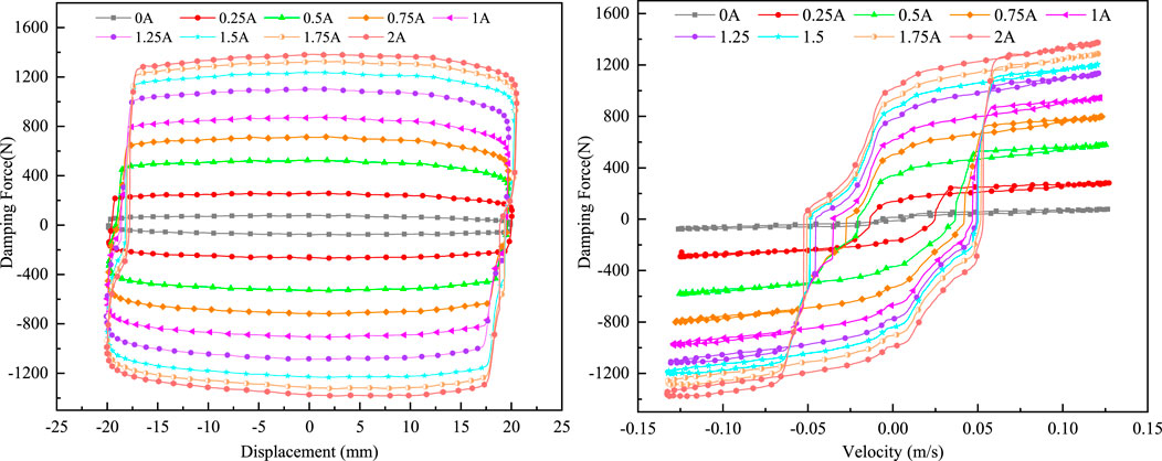
FIGURE 2. Dynamics performance of magnetorheological damper.
The analysis of the experimental results indicates that the designed MR damper’s hysteresis loop is full, with a maximum output damping force of approximately 1373 N, meeting the requirements for the use of magneto-rheological semi-active air suspension in the vehicle system.
In order to achieve accurate control of the semi-active magneto-rheological damper, the Bouc-Wen model was employed for parameter identification (Dominguez et al., 2004). The mathematical expression of the Bouc-Wen model is given by:
F: the output force; x: the displacemen; c0: the equivalent damping of the damper; k0: the equivalent stiffness of the damper;
Five groups of MR damper test data with different control currents (0A, 0.25A, 0.5A, 0.75A and 1A) were selected for fitting to verify the reliability of the Bouc-Wen model. The parameters of the Bouc-Wen model were identified by genetic algorithm for fitting. The comparison results are shown in Figure 3. The results show that the model fits well with the experimental results, proving that the model can be effectively used for semi-active control of magnetorheological dampers.
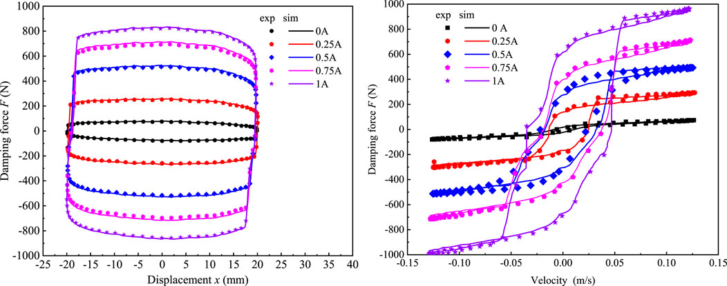
FIGURE 3. Comparison between Bouc wen model and experimental results.
2.2 Vehicle model of the suspension
The vehicle magneto-rheological semi-active air suspension is a complex vibration system with highly nonlinear characteristics. Therefore, establishing the mechanical model of the suspension system is fundamental for designing suspension controllers and analyzing suspension performance. In order to study the damping performance of the magneto-rheological semi-active air suspension and optimize its time delay issues, this paper establishes a 1/4 vehicle model of the suspension, as shown in Figure 4. The 1/4 vehicle suspension model is widely used due to its simplicity, considering only the vertical vibrations of the mass above and below the spring, without accounting for the pitch and roll vibrations of the vehicle body. Numerous studies have indicated that the 1/4 vehicle suspension model can accurately reflect the actual vibration state of the vehicle, and the calculated forces are reasonably accurate, meeting the requirements for practical engineering applications (Vivas-lopez et al., 2021; Yang et al., 2021; Li et al., 2021)
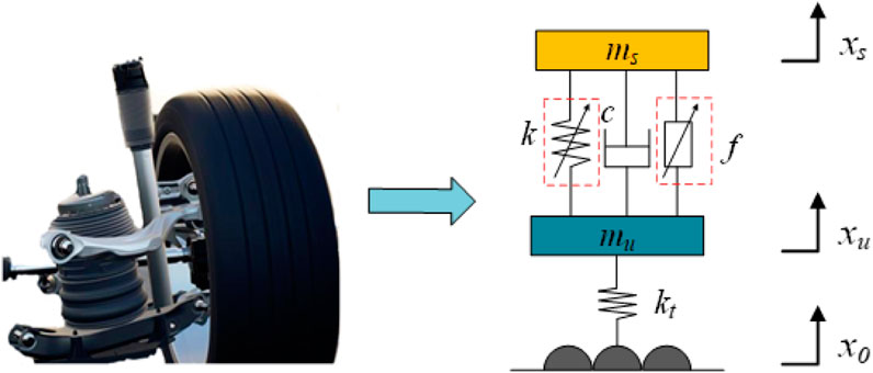
FIGURE 4. 1/4 vehicle suspension model.
The mechanical model established by Figure 4:
Selecting the state variables and output variables for the magneto-rheological semi-active air suspension as:
The state equation for the magneto-rheological semi-active air suspension is obtained as:
where
2.3 Road excitation model
The road surfaces over which vehicles travel include well-maintained and relatively random roads such as concrete roads, as well as roads with irregularities, bumps, speed bumps, etc. Therefore, this paper establishes a C-grade random road input model using filtered white noise to account for road irregularities and randomness:
When the road grade is at level C, simulations were conducted in Simulink at three different speeds: 18 km/h, 36 km/h, and 72 km/h. The resulting time-domain curves for random input under the same road grade at different speeds are shown in Figure 5. Analysis of the graph indicates that when the road grade remains constant, an increase in vehicle speed leads to a larger amplitude of random road input displacement.
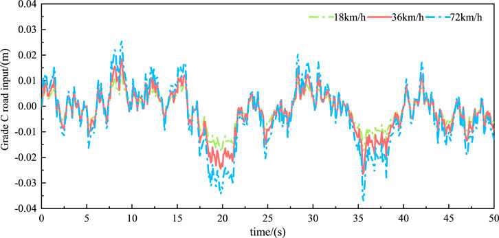
FIGURE 5. Grade C road input.
3 Controller design
The actual sliding mode control system faces issues such as lag and inertia, causing its trajectory to not constantly stay on the switching surface but rather oscillate near it. To optimize the chattering problem in sliding mode control, a combination of quantum genetic algorithm, fuzzy control principles, and sliding mode control strategy is employed.
3.1 Quantum genetic algorithm
Quantum Genetic Algorithm (QGA) is a probabilistic evolutionary algorithm that combines genetic algorithms with quantum computing. One significant advantage of genetic algorithms is their focus not only on the essence and optimization method of a problem but also on globally adaptive searches through a probability-driven approach using the objective function. This approach enables efficient handling of complex problems, showcasing remarkable adaptability and robustness (Ballinas et al., 2023). However, genetic algorithms have notable drawbacks, especially in control systems. Due to the continuous need for crossover, selection, and mutation operations during the algorithm’s execution, along with ongoing iterations, genetic algorithms suffer from a relatively slow convergence speed. This can impact the timeliness of control and make them susceptible to falling into local optimal solutions. In the field of quantum computing, quantum states are considered the fundamental units of information. Quantum computing leverages the properties of quantum states, such as entanglement, superposition, and interference, to perform computations, addressing issues present in traditional computing methods. These computations are carried out by operating on quantum bits using quantum logic gates.
QGA is constructed based on the representation of quantum state vectors. It applies the probability amplitude representation technique of quantum bits to the chromosome encoding process, allowing a chromosome to represent the superposition phenomenon of multiple states. Through the application of quantum logic gates, chromosome update operations are implemented, thereby achieving the goal of optimizing the solution.
In the application of QGA, the core unit of information is referred to as a quantum bit or qubit. A qubit can exist in a “0 state”, “1 state”, or as a combination state of the two quantum states. This paper discusses the evolutionary process and convergence in QGA under these two scenarios. A qubit can be described as:
Therefore, a quantum bit has the ability to simultaneously store and represent data in two states. A quantum bit string has the capability to store and represent 2N different solutions, exhibiting an exponential growth trend in space, which is significantly different from the linear growth of traditional Genetic Algorithms. QGA can operate on the stored 2N data simultaneously in a single computation, showcasing strong computational power and higher efficiency compared to traditional genetic algorithms.
QGA utilizes one or more quantum bits to store and represent a gene, and these genes collectively form a chromosome. If a quantum bit can be represented by a complex number pair (α, β), Then, a chromosome composed of m genes, each consisting of k bits, can be represented as follows:
i: chromosome index; k: number of qubits in a gene; t: current evolutionary generation of the chromosome; m: number of genes in the chromosome;
Because the chromosome is in a superposition state, traditional Genetic Algorithms cannot be used, and its evolutionary operations cannot handle chromosomes in a superposition state. However, quantum computing methods can handle superposition states. QGA uses quantum rotation operators to refresh the chromosome. The specific operation is as follows: by applying quantum gates to the ground states of quantum superposition states, interference and changes between them are induced, thereby altering the probability amplitudes of various ground states. The quantum rotation gate can be represented as:
The operation method can be represented as:
3.2 Fuzzy sliding mode control based on quantum genetic algorithm
The ideal sky-hook and ground-hook damping control proposed by Professor Karnopp (Karnopp et al., 1995) is taken as the reference object. The sky-hook and ground-hook damping control variables are as follows:
Define the error e as the integral of displacement error, velocity error and body mass displacement error, then:
Combined with the difference between the state variables of the semi-active suspension model and the ideal skyhook model, it can be concluded that:
Where: A: error state matrix; M: coefficient matrix; N: state variable matrix; B: Input error coefficient matrix; Fd is the input force of semi-active suspension.
For the magnetorheological semi-active air suspension system, the sliding surface of the sliding mode controller is designed as follows:
According to the existence condition of the sliding mode, the equivalent control force of the MR damper under the sliding mode control strategy is obtained. In order to improve the reaching phase of the sliding mode motion, the saturation function sat (s) is adopted on the basis of the switching control logic of the sign function. Therefore, the final system sliding mode control rate is:
In the absence of considering parameter uncertainties, if the value of k in equation is too small, it will lead to a prolonged time for the system to reach the sliding surface, and it may even fail to meet the reachability condition. On the other hand, if k is too large, it will cause severe chattering near the sliding surface. Therefore, it is necessary to consider parameter uncertainties. In order to suppress the chattering phenomenon, fuzzy control ideas are combined with sliding mode control. The specific method is to adjust k by fuzzyfying it based on the fuzzy value of s, thus adjusting the switching control
Choosing s as the input to the fuzzy controller, satisfying
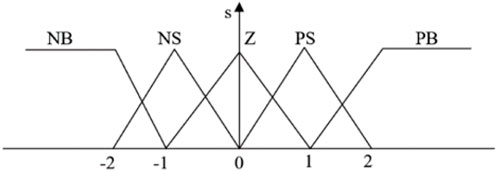
FIGURE 6. The membership function of input s.
Using QGA to optimize control rules, where control rules are defined as: If s is
The input of the fuzzy controller consists of 5 fuzzy sets, represented by s. Therefore, there are 52 control rules inside it, and each rule has a corresponding fuzzy value. The core task of QGA is to convert all control rules into quantum bits, i.e., encode the chromosome of the problem.
The fuzzy values corresponding to the five fuzzy rules {PB, PS, Z, NS, NB} are encoded, i.e., the fuzzy linguistic values are converted into binary codes that QGA can handle, and this constitutes the population initialization. The individual fitness value function uses the minimum sliding mode value

TABLE 1. Rotating angle adjustment strategy.
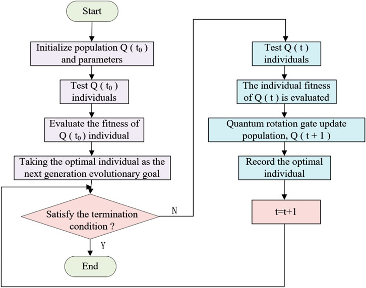
FIGURE 7. The specific operation method of QGA.
The control principle of the fuzzy sliding mode control based on quantum genetic algorithm (QFSMC) is illustrated in Figure 8.
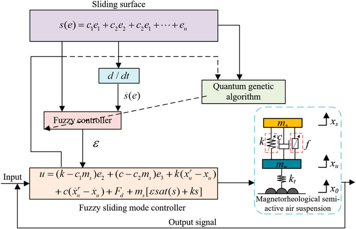
FIGURE 8. The control principle of QFSMC.
3.3 The QFSMC controller based on the Smith Predictor
The research on control algorithms has significantly improved the damping performance of semi-active suspensions. However, in practical implementation of semi-active control, inevitable factors such as control force calculation, signal acquisition and transmission, and actuator response introduce delays. These delays contribute to a lag in the output control force, and the issue of delay seriously affects the control quality of the suspension, potentially leading to vehicle instability (Uzunsoy et al., 2005). In the context of magnetorheological semi-active air suspension systems, there is typically a certain amount of pure delay, with delay times reaching up to several hundred milliseconds. This poses challenges in both vehicle modeling and control.
The Smith Predictor consists of a delay element and a model of the controlled system. The principle of prediction and compensation in the Smith Predictor involves adding a compensatory loop in parallel, in the reverse direction, within the closed-loop transfer function of the system controller. This addition is aimed at counteracting the original delay element, thereby enhancing the dynamic performance and stability of the system.
Assuming a non-delayed single-loop control system, the transfer function of this non-delayed system is:
r(s): input to the system; D(s): Transfer function of the controller; Gp(s): Transfer function of the controlled object; y(s): Output of the system.
Taking into account the impact of system delay, the transfer function of the controlled object becomes Gp(s)
Design a delay compensator
Where,
The control principle of a system with delay compensation using the Smith Predictor is illustrated in Figure 9.
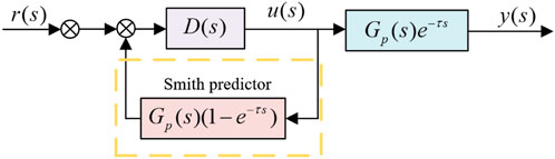
FIGURE 9. The control system of Smith predictor compensation.
Based on the above analysis, it is known that for a system controlled by the Smith Predictor, its output is only shifted in time compared to the original control system. In Section 3.2 of this paper, a QFSMC controller was designed for the magneto-rheological semi-active air suspension. According to the predictive control principle of the Smith Predictor, a compensation loop is added to the suspension system, as illustrated in Figure 10.
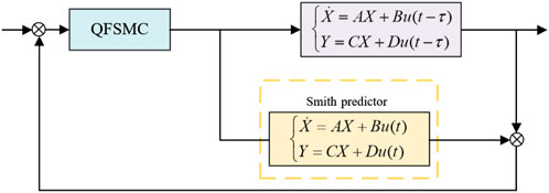
FIGURE 10. S-QFSMC controller schematic diagram.
4 Simulation and analysis
In order to verify the improvement of the designed S-QFSMC controller on the performance of the magneto-rheological semi-active air suspension, a comparison was made for the smoothness index of the vehicle under the same road excitation conditions between passive suspension, QFSMC-controlled suspension, and S-QFSMC-controlled suspension. To validate the applicability of the S-QFSMC controller for various road conditions, a C-grade random road excitation was used as the road excitation condition, and simulations were conducted in Simulink. The relevant simulation parameters are shown in Table 2.

TABLE 2. System simulation model parameters.
4.1 Time-domain simulation analysis
The smoothness evaluation index of vehicle motion can be measured by the acceleration of the spring-loaded mass, the rationality of the suspension working space can be measured by the suspension dynamic travel, and the operational stability of the vehicle can be measured by the tire displacement. The simulation results of the system are shown in Figure 11.
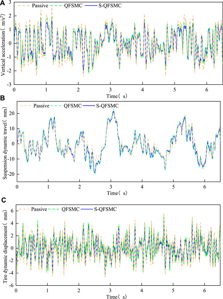
FIGURE 11. Suspension performance in the time domain. (A) Body acceleration (B) Suspension dynamic travel, (C) Tire dynamic displacement.
From the analysis of simulation results, the improvement rate of suspension performance index compared to passive suspension is shown in Figure 12. Compared to the passive suspension, both the QFSMC controller and the S-QFSMC controller improve the suspension performance, with the S-QFSMC controller showing a better overall improvement effect, validating the effectiveness of the designed controller. The improvement rate of suspension dynamic travel is negative, indicating that the body fluctuation during vehicle travel is smaller, and the suspension performance is better.
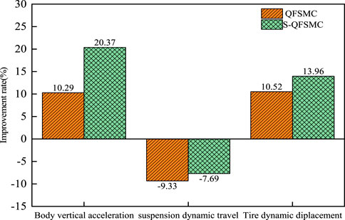
FIGURE 12. The improvement rate of suspension performance index.
4.2 Frequency-domain simulation analysis
The resonance frequencies of most human organs are primarily concentrated in the range of 2–10 Hz. Prolonged exposure to resonance states can lead to spinal injuries and gastrointestinal diseases. To more intuitively illustrate the improvement in subjective human perception due to suspension performance, frequency domain simulation analysis was conducted on the magnetorheological semi-active air suspension under different controllers. The simulation results of Power Spectral Density are depicted in Figure 13.
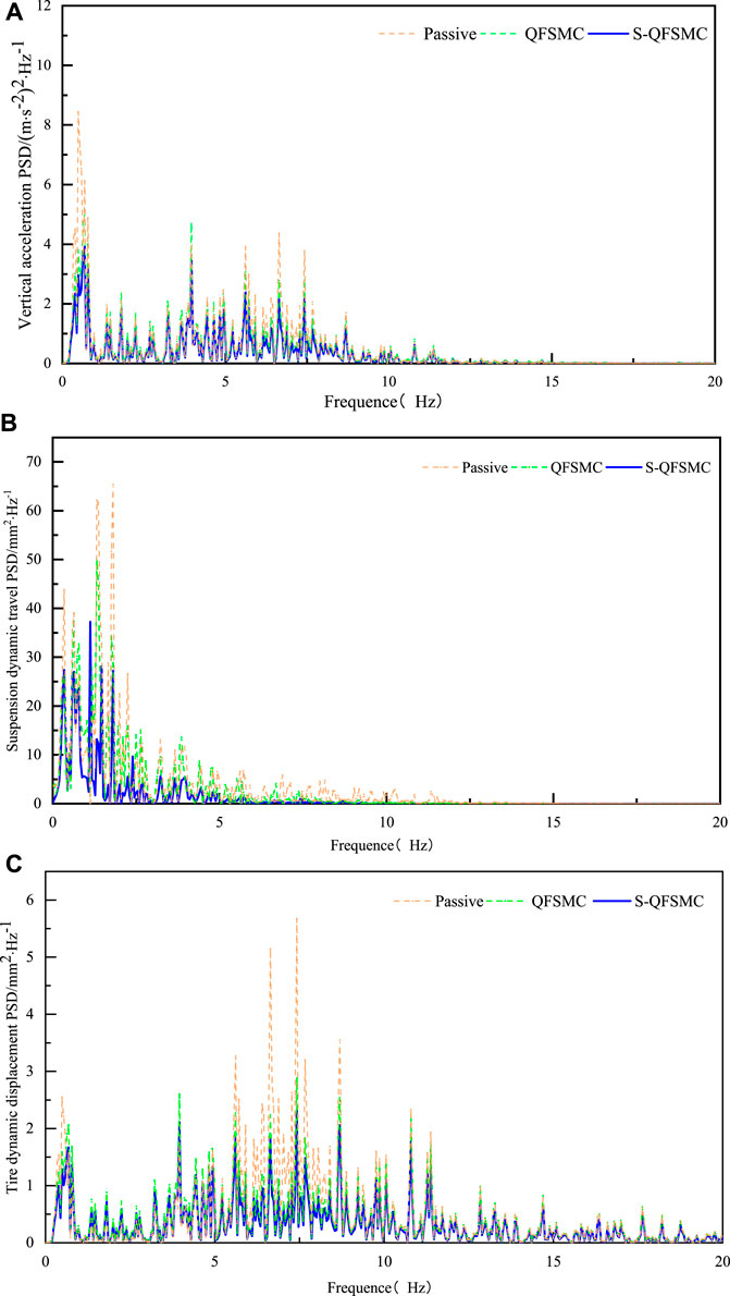
FIGURE 13. Suspension performance in the frequency domain. (A) Body acceleration, (B) Suspension dynamic travel, (C) Tire dynamic displacement.
The simulation results indicate that, in the low-frequency range, compared to the passive suspension, both the QFSMC controller and S-QFSMC controller improve the suspension performance, with the S-QFSMC controller showing a more comprehensive improvement. This validates the effectiveness of the designed controllers. In the high-frequency range, the suspension spectra of the passive suspension, QFSMC controller, and S-QFSMC controller almost overlap. The simulation results suggest that the magnetorheological semi-active air suspension system controlled by the S-QFSMC controller can reduce the low-frequency resonance between the vehicle and the occupants, thereby improving the operational safety of the vehicle and enhancing ride comfort.
5 Conclusion
This paper presents the design of a S-QFSMC based on the Smith predictor for a vehicle with a magnetorheological semi-active air suspension. The study establishes a mechanical model for the 1/4 vehicle with magnetorheological semi-active air suspension, considering time delays. The S-QFSMC controller is designed accordingly. Simulation analyses for vehicle ride comfort are conducted in the MATLAB/Simulink environment. The results indicate that, compared to passive suspension, both the QFSMC and S-QFSMC controlled suspensions exhibit improvements. Moreover, the S-QFSMC controller demonstrates superior overall enhancement, validating the effectiveness of the proposed controller.
The simulation approach proposed in this paper provides a theoretical basis and reference direction for further testing on actual vehicles. It offers theoretical and technical support for the development of high-performance magnetorheological semi-active air suspension systems for vehicles. In the future work, considering the nonlinear diversity of delay, the impact of delay characteristics of actuators and controllers on suspension performance will be further investigated.
Data availability statement
The original contributions presented in the study are included in the article/Supplementary material, further inquiries can be directed to the corresponding author.
Author contributions
GL: Resources, Writing–review and editing. YG: Validation, Writing–original draft. QL: Resources, Writing–original draft. HX: Methodology, Writing–review and editing. DC: Software, Writing–review and editing. LZ: Software, Writing–review and editing. JD: Formal Analysis, Writing–review and editing. GH: Conceptualization, Writing–review and editing.
Funding
The author(s) declare financial support was received for the research, authorship, and/or publication of this article. The National Natural Science Foundation of China (52165004), Natural Science Foundation Project of Jiangxi Province (20232BAB204041), Key R&D project of Jiangxi Province of China (20212BBE51009), Key Program for International S&T Cooperation Project of Jiangxi Province of China (20232BBH80010), Jiangxi Graduate Student Innovation Special Fund Project (YC2023-S463), Double Height Project of Jiangxi Province Human Resources and Social Security Department in 2022.
Conflict of interest
Author JD was employed by Jiangxi Wushiling Automobile Co., Ltd.
The remaining authors declare that the research was conducted in the absence of any commercial or financial relationships that could be construed as a potential conflict of interest.
Publisher’s note
All claims expressed in this article are solely those of the authors and do not necessarily represent those of their affiliated organizations, or those of the publisher, the editors and the reviewers. Any product that may be evaluated in this article, or claim that may be made by its manufacturer, is not guaranteed or endorsed by the publisher.
References
Abdel-Rohman, M. (2021). Effect of the time delay on the magnitude of the onset galloping wind speed in semiactive controlled suspension bridges. J. Eng. Res. 9 (3B), 25–42. doi:10.36909/jer.v9i3b.9869
Ballinas, E., and Montiel, O. (2023). Hybrid quantum genetic algorithm with adaptive rotation angle for the 0-1 Knapsack problem in the IBM Qiskit simulator. Soft Comput. 27 (18), 13321–13346. doi:10.1007/s00500-022-07460-7
Cao, D. P., Song, X. B., and Ahmadian, M. (2011). Editors' perspectives: road vehicle suspension design, dynamics, and control. Veh. Syst. Dyn. 49 (1-2), 3–28. doi:10.1080/00423114.2010.532223
Dominguez, A., Sedaghati, R., and Stiharu, I. (2004). Modelling the hysteresis phenomenon of magnetorheological dampers. Smart Mater. Struct. 13 (6), 1351–1361. doi:10.1088/0964-1726/13/6/008
Dong, X. M., Yu, M., Huang, S. L., et al. (2006). Time delay and compensation in automotive magneto-rheological semi-active control system. Comput. Simul. 23 (4), 229–232. doi:10.3969/j.issn.1006
Gao, J., and Wu, F. Q. (2021). Analysis and optimization of the vehicle handling stability with considering suspension kinematics and compliance characteristics. Adv. Mech. Eng. 13, 1687. doi:10.1177/16878140211015523
Hamersma, H. A., and Els, P. S. (2021). Vehicle suspension force and road profile prediction on undulating roads. Veh. Syst. Dyn. 59 (10), 1616–1642. doi:10.1080/00423114.2020.1774067
Hao, Y. L., Zhang, J. G., and Chen, Z. M. (2007). Adaptive fuzzy sliding mode control for a class of nonlinear systems. J. Syst. Simul. 19 (14), 3230–3233. doi:10.3969/j.issn.1004-731X.2007.14.027
Hu, G. L., Ying, S. C., Qi, H. N., Yu, L., and Li, G. (2023b). Design, analysis and optimization of a hybrid fluid flow magnetorheological damper based on multiphysics coupling model. Mech. Syst. Signal Process. 205, 110877. doi:10.1016/j.ymssp.2023.110877
Hu, G. L., Zhou, F., Yang, X., Wang, N., Yu, L., and Li, G. (2023a). Analysis of pressure drop and response characteristics of an enhanced radial magnetorheological valve based on magneto-fluidic coupling. J. Magnetism Magnetic Mater. 589, 171589. doi:10.1016/j.jmmm.2023.171589
Hua, C. R., Zhao, Y., Lu, Z. W., and Ouyang, H. (2018). Random vibration of vehicle with hysteretic nonlinear suspension under road roughness excitation. Adv. Mech. Eng. 10, 1687. doi:10.1177/1687814017751222
Jeong, H. K., Jack, T., et al. (2018). The effect of a multi-axis suspension on whole body vibration exposures andphysical stress in the neck and low back in agricultural tractor applications. Appl. Ergon. 68, 80–89. doi:10.1016/j.apergo.2017.10.021
Jiang, X. H., and Chen, T. H. (2023). Design of a BP neural network PID controller for an air suspension system by considering the stiffness of rubber bellows. Alexandria Eng. J. 74, 65–78. doi:10.1016/j.aej.2023.05.012
Karnopp, D. (1995). Active and semi-active vibration isolation. J. Vib. Acoust. 117 (B), 177–185. http://mechanicaldesign.asmedigitalcollection.asme.org/on01/29/2016. doi:10.1115/1.2836452
Li, W. F., Dong, X. M., Yu, J. Q., Xi, J., and Pan, C. (2021). Vibration control of vehicle suspension with magneto-rheological variable damping and inertia. J. Intelligent Material Syst. Struct. 32 (13), 1484–1503. doi:10.1177/1045389X20983885
Ran, M., and Cuong, M. D. (2020). Comfort-oriented semi-active matching design with a magneto-rheological air suspension mechanism. Iran. J. Sci. Technology-Transactions Mech. Eng. 45 (3), 699–709. doi:10.1007/s40997-020-00393-2
Sun, L. Q., Wang, Y., Li, Z. X., Geng, G., and Liao, Y. G. (2022). H∞ robust control of interconnected air suspension based on mode switching. IEEE Access 10, 62377–62390. doi:10.1109/ACCESS.2022.3178105
Uzunsoy, E., and Olatunbosun, O. A. (2005). A study of the effect of rear suspension auxiliary roll damping on vehicle-handling dynamics. Proc. Institution Mech. Eng. Part D- J. Automob. Eng. 219 (D1), 21–30. doi:10.1243/095440705X6523
Vivas-lopez, C. A., Tudon-martinez, J. C., Estrada-vela, A., de Jesus Lozoya-Santos, J., and Morales-Menendez, R. (2021). Damping variation effects in vehicle semi-active MR suspensions: a stress concentration analysis. Front. Mater. 8. doi:10.3389/fmats.2021.590390
Yang, C. G., Yang, X., Zhou Y, , et al. (2023). Research on the performance of magnetorheological semi-active suspension with stepped by-pass valve based on fuzzy PID control. J. Magnetics 28 (3), 277–285. doi:10.4283/JMAG.2023.28.3.277
Yang, C. Y., Xia, J. W., Park, J. H., Shen, H., and Wang, J. (2021). Sliding mode control for uncertain active vehicle suspension systems: an event-triggered H∞ control scheme. Nonlinear Dyn. 103 (4), 3209–3221. doi:10.1007/s11071-020-05742-z
Zhang, Y. E., and Chen, C. J. (2024). Robust predictive compensation control for lateral magnetorheological semi-active suspension of high-speed trains with time delay. Automatika 65 (1), 14–33. doi:10.1080/00051144.2023.2277492
Keywords: semi-active air suspension, magneto-rheological damper, time delay, quantum genetic algorithm, sliding mode control
Citation: Li G, Gan Y, Liu Q, Xu H, Chen D, Zhong L, Deng J and Hu G (2024) Performance analysis of vehicle magnetorheological semi-active air suspension based on S-QFSMC control. Front. Mater. 11:1358319. doi: 10.3389/fmats.2024.1358319
Received: 19 December 2023; Accepted: 09 February 2024;
Published: 22 February 2024.
Edited by:
Yang Yu, University of New South Wales, AustraliaCopyright © 2024 Li, Gan, Liu, Xu, Chen, Zhong, Deng and Hu. This is an open-access article distributed under the terms of the Creative Commons Attribution License (CC BY). The use, distribution or reproduction in other forums is permitted, provided the original author(s) and the copyright owner(s) are credited and that the original publication in this journal is cited, in accordance with accepted academic practice. No use, distribution or reproduction is permitted which does not comply with these terms.
*Correspondence: Qianjie Liu, qjliu@ecjtu.edu.cn