Design of novel microstrip patch antenna for millimeter-wave B5G communications
 Jun Jiat Tiang1
  Imran Khan
 Dag Øivind Madsen
- 1Faculty of Engineering, Centre for Wireless Technology, Multimedia University, Cyberjaya, Malaysia
- 2Department of Computer Science and Information Technology, Applied College of Computer and Information Science, Princess Nourah Bint Abdulrahman University, Riyadh, Saudi Arabia
- 3Department of Electrical Engineering, University of Engineering and Technology, Peshawar, Pakistan
- 4Islamic University Centre for Scientific Research, The Islamic University, Najaf, Iraq
- 5Department of Computer Science and Engineering, National Chung Hsing University, Taichung, Taiwan
- 6University of South-Eastern Norway, Hønefoss, Norway
Introduction: The simplicity of integration and co-type features of microstrip antennas make them intriguing for a broad variety of applications, particularly with the growing usage of mmWave bands in wireless communications and the constant rise in data transfer in communication situations.
Method: This paper proposes a novel design of micrstrip patch antenna for mmWave B5G communication. The main idea is to realize four-mode antenna the operates in four different frequencies. The geometry is rectangular patch whose resonance frequency is adjusted by varying the walls and pins of the structure.
Results: Simulation results show that the proposed antenna design has improved fractional bandwidth and performance as compared with existing antennas.
Discussion: The observed curve indicates that, in agreement with the modeling findings, there are four resonance spots in the operational frequency region of 2.5–3.4 GHz: 2.68 GHz, 2.9 GHz, 3.05 GHz, and 3.3 GHz, which correspond to TM1/2,0, TM3/2,0, and TMRS, respectively, and TM1/2,2 four resonant modes, within the frequency range, the observed antenna gain peak is around 9 dBi, which is consistent with the measured results.
1 Introduction
Millimeter-wave (mmWave) technologies, which need more capacity for high-speed data transmission, have been more in demand in the wake of beyond 5G (B5G) development. The low-profile planar structure of the microstrip antenna is easily conformable to carriers with shapes such as cylinders and curved surfaces, and has been widely used. However, the low-profile structure also causes the microstrip patch antenna to behave like a leaky wave cavity, with resonance characteristics similar to an RLC parallel resonant circuit and a high Q value, so the impedance bandwidth of the antenna is very narrow (Ullah et al., 2019; Kumar et al., 2022). Currently, there are three main methods to broaden the bandwidth of microstrip antennas: 1) Use high thickness or low dielectric constant dielectric substrates to reduce the equivalent circuit Q value, thereby increasing the impedance bandwidth (Ullah et al., 2019; Kumar et al., 2022), but the surface wave leakage in this planar antenna increases (Liu et al., 2018a; Ge et al., 2018; Hao et al., 2019), resulting in poor radiation efficiency. 2) Improve the feeding method, such as electromagnetic coupling feeding (Fan et al., 2018; Soliman et al., 2022), L-shaped probe (Fan et al., 2018; Farooq et al., 2021; Soliman et al., 2022) or M-shaped probe (Yang et al., 2020a; Kumar et al., 2021) feeding, etc., but the antenna radiation pattern will change with frequency, and the cross-pole higher. 3) Use parasitic elements to combine multiple coupled resonance modes to increase the bandwidth, but its volume will increase a lot (Beguad et al., 2018; Srivastava et al., 2020; Karami et al., 2022). The authors in (Hannan et al., 2021; Dicarlofelice et al., 2022) etched U-shaped grooves on the radiation patch and introduced additional resonance modes near the main resonance point to broaden the bandwidth, but the thickness of the antenna was larger. Similar structures include single-layer E-shaped microstrip antenna, stacked E-shaped microstrip antenna (Dong et al., 2021), etc. Etching a slit on the surface of the patch antenna changes the surface current distribution to achieve dual-frequency resonance. Adjusting the position and size of the slit can make the resonant frequencies closer to each other, and construct dual-mode resonance to obtain wide-band characteristics. The authors in (Tewary et al., 2021) proposed loading multiple slits on a rectangular patch to simultaneously excite two orthogonal modes, TM10 and TM01, to achieve bandwidth enhancement and compact structure, achieving 3.8% on the basis of a low profile of 0.01λ0 impedance bandwidth, but due to the use of high-loss FR4 substrate and etching of multiple slits, the antenna gain is low and the cross-polarization is as high as −5 dB. The authors in (Khan et al., 2022) loaded a short circuit on the circular patch needle, the resonant frequencies of the TM01 and TM02 modes are reconstructed, a wide impedance bandwidth of 18% is achieved in the monopole radiation mode, and the low profile characteristics of 0.024λ0 can be maintained. The disadvantage is that the radiation peak cannot be stable within the operating frequency band. The authors in (Chinnagurusamy et al., 2021) placed short-circuit pins under the equilateral triangle patch and etched V-shaped gaps to excite the TM10 and TM20 modes, making the antenna bandwidth reach 32%, but the antenna thickness also increased to 0.09λ0. The authors in (Yang et al., 2020b) designed a patch antenna based on TM1/2,0, TM1/2,2 and TM3/2,2 three-mode resonance, and improved the radiation performance of the antenna by loading multiple short-circuit walls, which enhances the bandwidth to 26.2% at a profile height of 0.059λ0. The authors in (Lu et al., 2018) designed a broadband circular sector patch antenna based on TM4/3,1 and TM8/3,1 modes. The design criteria were determined by multi-mode dipole and cavity models. At 0.05λ0, a useable radiation bandwidth of 14.5% is achieved under low profile conditions. The authors in (Sharaf et al., 2020) designed a three-mode sector patch antenna based on TM12/17,1, TM36/17,1 and TM60/17,1 based on the zero-frequency scanning working principle of a direct electric dipole, the antenna operating bandwidth is enhanced to 24%, and the thickness is maintained at 0.05λ0.
In order to address the above problem, this paper reduces the high cross-polarization of the H-plane pattern by loading a short-circuit wall on the non-radiating side of the rectangular patch, and loading a short-circuit pin under the patch to increase the resonant frequency of the TM1/2,0 mode.
The main contributions of this work are as follows.
• In the TM3/2,0 mode, a rectangular slot is cut at the zero current position to excite the radiation slot mode, forming a three-mode resonant patch antenna with low profile, wide bandwidth and reduced H-plane cross-polarization performance.
• The antenna is only 3 mm thick (0.029λ0) In this case, an impedance bandwidth of 18% (2.64–3.17 GHz) is achieved, and the H-plane cross-polarization is reduced to below −20 dB.
• By appropriately increasing the patch width and adjusting the antenna structure, the frequency of the TM1/2,2 mode is reduced and brought closer to the TM1/2,0, TM3/2,0 and TMRS modes, thereby further achieving four-mode resonance while maintaining the antenna with the thickness unchanged (3 mm), the bandwidth is further increased to 21.7% (2.67–3.32 GHz).
The remaining of this paper is organized as follows. In Section 2, the proposed model design and working principle is discussed. In Section 3, the practical implementation of the proposed antenna is presented and the experimental analysis is performed with comparative evaluation. Finally, Section 4 concludes the paper.
2 Model design and working principle
2.1 Developing three-mode broadband patch antennas
The illustration in Figure 1A shows a rectangular microstrip patch antenna (Px = 56 mm, Py = 100 mm). By loading short-circuit walls on three sides. It is even-order mode can be suppressed and the E-plane (x-z plane) high side lobes of the pattern and high cross-polarization of the H-plane (y-z plane) pattern (Srivastava et al., 2020; Subha et al., 2020; Koutinos et al., 2022), the resonance of the antenna in the three modes are TM1/2,0, TM3/2,0, TM1/2,2, and frequencies f1/2,0, f3/2,0, f1/2,2 are 1.35 GHz, 2.84 GHz, and 3.21 GHz respectively. An array of four short-circuiting pins (shown in the inset of Figure 1B) is then loaded under the radiation patch, boosting f1/2,0 to around 2.68 GHz while keeping f3/2,0 at 2.83 GHz, f1/2,2 is also boosted to 3.75 GHz. Finally, a rectangular gap is etched near the zero current line of the TM3/2,0 mode (as shown in the inset of Figure 1C) to excite the gap radiation mode TMRS (Subha et al., 2020; Koutinos et al., 2022). The TMRS mode operates at 3.07 GHz, close to f1/2,0 and f3/2,0, the impact of this gap on the TM1/2,0 and TM3/2,0 modes is controllable, achieving three-mode resonance based on TM1/2,0, TM3/2,0 and TMRS. Through these measures, the bandwidth and radiation performance of the antenna are improved.
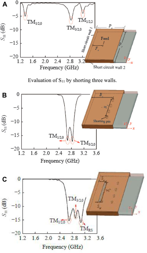
Figure 1. Development of patch antenna with three-mode capability. (A) Evaluation of S11 by shorting three walls. (B) Shorting four pins. (C) Rectangle etching.
2.2 Design parameters and analysis
The number and position of short-circuit pins, the length, width and position of the gap are several key parameters that affect the performance of the patch antenna, and they will be analyzed in depth.
2.2.1 Load short circuit pin reassign TM1/2,0 mode
By appropriately adding short-circuit pins, the resonant frequency of the TM1/2,0 mode can be effectively controlled, while it has little effect on the TM3/2,0 mode, and the frequency ratio can be significantly reduced: f3/2,0/f1/2,0. Figure 2 shows how the resonant frequency and frequency ratio of the antenna change with the position and number of short-circuit pins. Figure 2A shows the case where a single pin is located Bx from the short-circuit wall along the x-direction at the center plane of the patch (Lu et al., 2017; Liu et al., 2018b; Lee et al., 2019). When Bx/Px = 0.1, f1/2,0 and f3/2,0 are approximately 1.4 GHz and 2.9 GHz respectively, resulting in a large frequency ratio of f3/2,0/f1/2,0 = 2.1. When Bx/Px reaches about 0.75, because the short-circuit pin is properly placed around the node line of the electric field of the TM3/2,0 mode, a minimum f3/2,0/f1/2,0 of about 1.55 is obtained. After Bx/Px is greater than 0.75, the frequency ratio of the dual modes gradually increases (Liu et al., 2017a; Jian et al., 2020; Wu et al., 2020), moving away from each other. The results show that the minimum frequency ratio can be obtained when Bx is 0.75Px.

Figure 2. Variation of resonant frequency with different values of shorting pins. (A) With single short pin. (B) With two pins short. (C) With three pins short. (D) With four pins short.
Figure 2B shows the analysis of loading two short-circuit pins when Bx/Px = 0.75. As By/Py increases from 0.1 to 0.9, f1/2,0 has a maximum value of 2.2 GHz at By/Py = 0.3, whereas f3/2,0 almost remains around 2.85 GHz. Therefore, by choosing Bx/Px = 0.75 and By/Py = 0.3, the minimum value of f3/2,0/f1/2,0 ≈ 1.30 can be achieved. Figures 2C, D further study f1/2,0, f3/2,0 and f3/2,0/f1/2,0- when loaded with three and four short-circuit pins respectively at Bx/Px = 0.75 (Liu et al., 2017b; Gao et al., 2019; Ma et al., 2021). Compared with Figures 2A, B, similar trends for f1/2,0 and f3/2,0 are obtained. Therefore, when four short-circuit pins are loaded, and Bx/Px = 0.75 and By/Py = 0.5, the minimum value of f3/2,0/f1/2,0 ≈ 1.06 can be reached.
2.2.2 Etching gap to excite TMRS mode
To further broaden the impedance bandwidth of the antenna, a linear groove is etched on the radiation patch near the TM3/2,0 mode zero current line to excite the TMRS mode of the patch antenna and move it closer to TM1/2,0 and TM3/2,0 mode (Cao et al., 2021; Liu, 2021; Cao et al., 2022). By appropriately modifying the trunking length (Sy), TM3/2,0 and TMRS modes can be combined to extend the bandwidth. It can be seen from Figure 3A that as Sy increases from 40 mm to 50 mm, fRS drops sharply from 3.5 GHz to 3.1 GHz, but f1/2,0 and f3/2,0 remain unchanged, so to obtain the widest bandwidth, Sy = 50 mm (Chung et al., 2022; Jiang and Li, 2022). Further adjust the gap position (Sx) and width (Sw) to analyze the impedance matching problem. Figures 3B, C show that Sx increases from 16.7 mm to 17.7 mm (Wu et al., 2020), Sw increases from 2 mm to 4 mm. The impedances are not always well matched, and only when Sx = 17.2 mm and Sw = 3 mm can a wider bandwidth and good impedance matching be achieved.
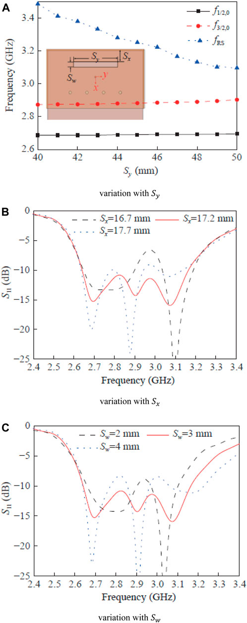
Figure 3. Impact of trunking length on the resonant frequency of the antenna. (A) Variation with Sy. (B) Variation with Sx. (C) Variation with Sw.
What needs to be pointed out here is that the TMRS mode excited by the loading gap also radiates electromagnetic energy. Since the resonant frequencies of the TMRS mode and the TM3/2,0 mode are close to each other, when the two slots operate at the same time (Mao et al., 2022a; Mao et al., 2022b; Dai et al., 2023), they will affect the pattern of the TM3/2,0 mode, causing the main beam direction to be deflected. The resonant frequency of TM1/2,0 mode is lower, and the frequency separation from TMRS is large. The electrical distance between them is very small for the TM1/2,0 mode. Therefore, the loading gap has little impact on the pattern of the TM1/2,0 mode.
2.2.3 The impact of loading short-circuit wall 2
To verify the effect of loading short-circuit wall 2 on H-plane cross-polarization, this paper uses a three-mode resonant broadband antenna without loading short-circuit wall 2 for comparison. To make both antennas resonate in the same mode and have close operating frequencies, the structure is optimized by adjusting the short-circuit pins, the position and size of the gaps, etc (Li et al., 2021a; Dai et al., 2022; Zhang et al., 2023a). Figure 4A shows the port reflection coefficients of the two antennas. It can be seen that they have three identical resonance modes, but the bandwidth of the antenna without short-circuit wall 2 is slightly wider. Figures 4B–D is a comparison of the H-plane radiation patterns of the two antennas in three modes (Zhang et al., 2023b; Wang et al., 2023). It can be seen that the cross-polarization of the H-plane of the antenna loaded with short-circuit wall 2 is reduced by more than 15 dB, proving that short-circuit wall 2 can greatly improve the radiation performance of the antenna in the far area.
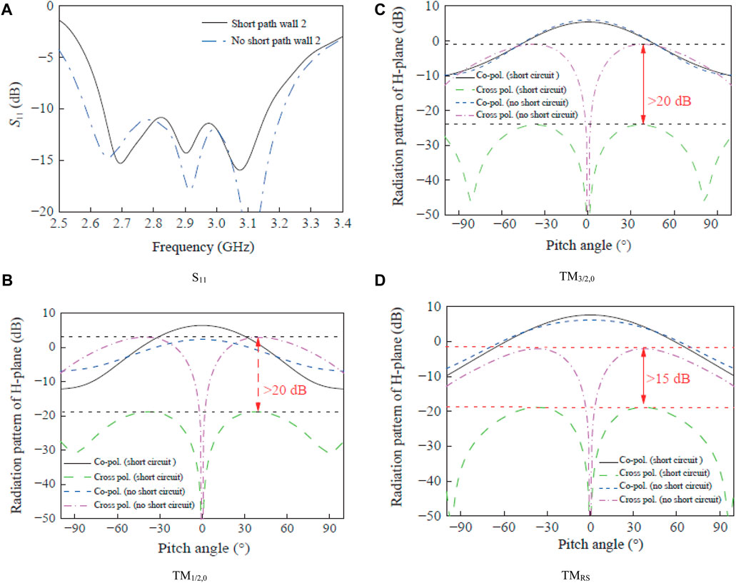
Figure 4. Impact of loading short-circuit wall 2 under different operating conditions. (A) S11. (B) TM1/2,0. (C) TM3/2,0. (D) TMRS.
2.2.4 Implementation of three-mode antenna and experimental results
Figure 5A shows the top view and side view of the three-mode patch antenna, and its cross-sectional height is 0.029λ0 (3 mm). Figure 5B shows the simulated and measured port return loss |S11|, and compares it with a conventional planar inverted-F antenna (PIFA) (Zhou et al., 2022a; Zhou et al., 2022b; Wen et al., 2023). It can be found from Figure 5B that there are three minimum values in the operating frequency band of 2.6–3.2 GHz, which are consistent with the three simulated resonance modes, namely, TM1/2,0, TM3/2,0 and slot mode (TMRS). Due to the combination of three resonance modes, the measured center bandwidth extends to 18% (from 2.64 to 3.17 GHz), which is 3.4 times the traditional PIFA center bandwidth (5.2%, 2.81–2.96 GHz).
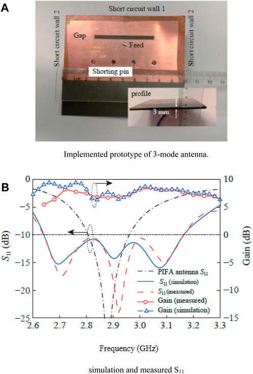
Figure 5. Implemented prototype and return loss of three-mode microstrip patch antenna. (A) Implemented prototype of 3-mode antenna. (B) Simulation and measured S11.
Figure 6 further shows the simulation and test pattern of the antenna at three resonance points. Due to the asymmetric structure of the antenna along the x-direction, the radiation pattern is slightly tilted, and the simulation results are in good agreement with the measured results (Gao et al., 2019; Yang et al., 2023a; Jannat et al., 2023). In addition, due to the loading of short-circuit wall 1, the side lobes of the E-plane (x-z plane) radiation pattern are lower. After loading the short-circuit wall 2, the cross-polarization of the H-plane (y-z plane) radiation pattern is better. The overall gain within the frequency band is greater than 6.5 dBi, and the peak gain is about 8 dBi.
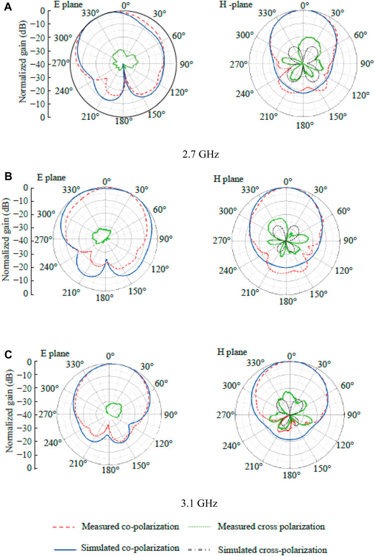
Figure 6. Comparison of radiation pattern and normalized gain of three-mode antenna. (A) 2.7 GHz. (B) 2.9 GHz. (C) 3.1 GHz.
3 Implementation and analysis of four-mode microstrip antenna
It can be seen from Figure 1B that as the short-circuit pin is loaded, the resonant frequency f1/2,2 of the TM1/2,2 mode will be far away from f3/2,0 and cannot be directly used to increase the bandwidth (Chen et al., 2022a; Yin et al., 2022; Jiang and Xu, 2023). The resonant frequency (fmn) of TMmn in traditional PIFA can be obtained from the cavity model theory:
In the formula:
The specific parameter analysis of the four-mode resonant antenna is similar to that in Section 2.2 and will not be repeated here. The specific structure of the four-mode resonant broadband antenna is shown in Figure 7A, and the antenna structural parameters are shown in Table 1. Figure 7B shows the simulated and measured return loss and gain (Hu et al., 2019; Liu et al., 2022). It can be found from the measured curve that there are four resonance points in the operating frequency band of 2.5–3.4 GHz: 2.68 GHz, 2.9 GHz, 3.05 GHz, 3.3 GHz, corresponding to TM1/2,0, TM3/2,0, TMRS respectively, and TM1/2,2 four resonant modes, consistent with the simulation results. The measured antenna gain peak within the frequency band is approximately 9 dBi. The small differences between simulation and actual measurements of return loss and gain are mainly caused by processing errors (Chen et al., 2022b). Due to the combination of four resonant modes, the measured center bandwidth of the antenna is further extended from 18% (2.64–3.17 GHz) of the three-mode antenna to 21.7% (2.67–3.32 GHz).

Figure 7. Implemented prototype of four-mode antenna and evaluation of return loss. (A) Decomposed and top view. (B) S11 and gain comparison.

Table 1. Physical parameters of the proposed four-mode antenna.
Figure 8 further shows the electric field distribution corresponding to these four modes. In Figure 8A, there is only one zero value line in the y direction, corresponding to the TM1/2,0 mode. In Figure 8B, two zero value lines in the y direction appear, corresponding to the TM3/2,0 mode (Li et al., 2021b; Xu et al., 2022; Xu et al., 2023b). In Figure 8C, only the radiation around the gap is strong (Huang et al., 2018; Min et al., 2023; Min et al., 2024), and the rest are weak, corresponding to the TMRS mode. In Figure 8D, there is a zero value line in the y direction, and two zero points appear in the x-direction, corresponding to the TM1/2,2 mode (Huang et al., 2023; Huang and Liu, 2023; Lan et al., 2024). Figures 9A–D further shows the four resonance modes of the four-mode broadband antenna (Lu and Osorio, 2018; Yang et al., 2023b; Gao et al., 2023). The simulation and measured diagrams at the points are in good agreement with the actual measurement results (Chen et al., 2022c; Xu et al., 2023c).
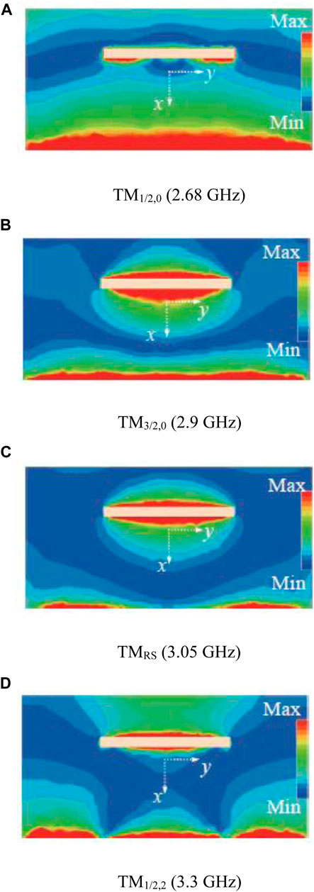
Figure 8. Comparison of E-field distribution in different modes and frequencies. (A) TM1/2,0 (2.68 GHz). (B) TM3/2,0 (2.9 GHz). (C) TMRS (3.05 GHz). (D) TM1/2,2 (3.3 GHz).
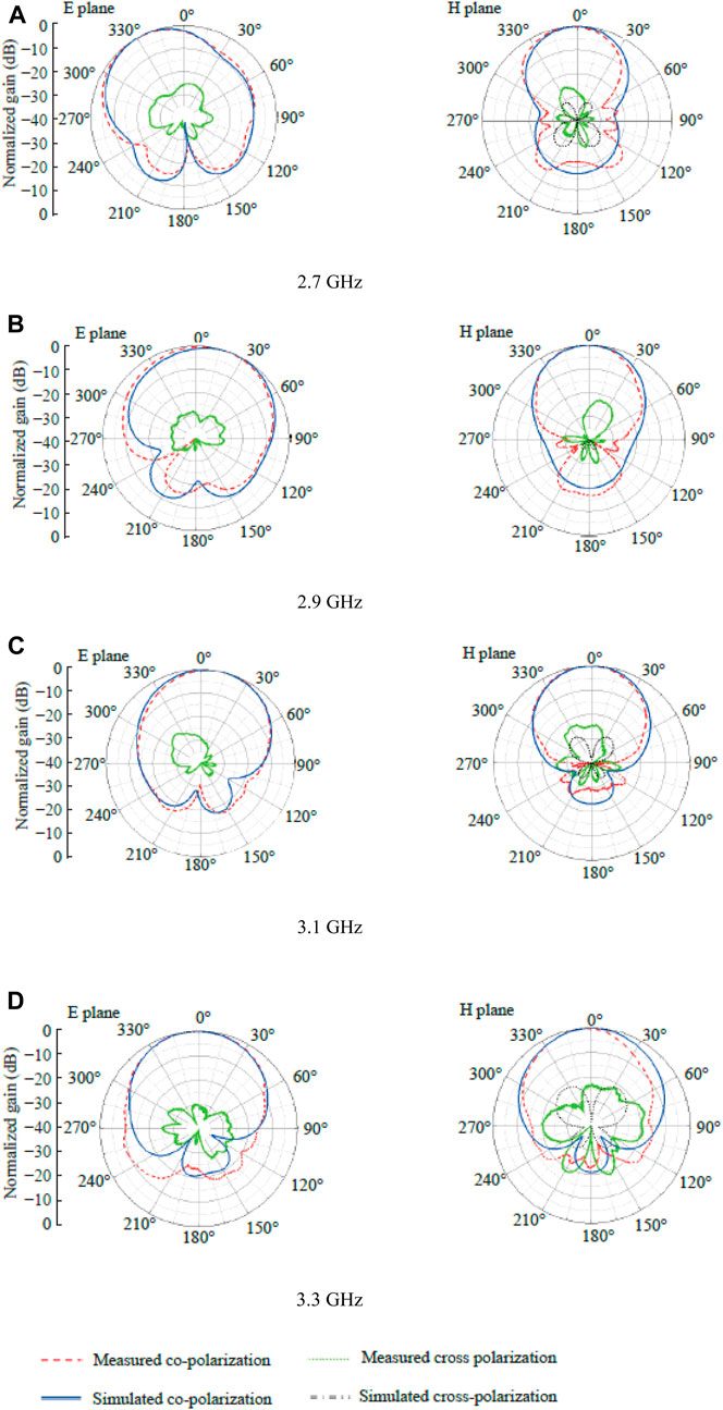
Figure 9. Comparison of radiation patter and normalized gain of four-mode microstrip antenna. (A) 2.7 GHz. (B) 2.9 GHz. (C) 3.1 GHz. (D) 3.3 GHz.
Table 2 further shows the comparison between the antenna designed in this article and the reference broadband antennas. It can be seen that the proposed antenna has comprehensive advantages in terms of thickness and electrical performance.
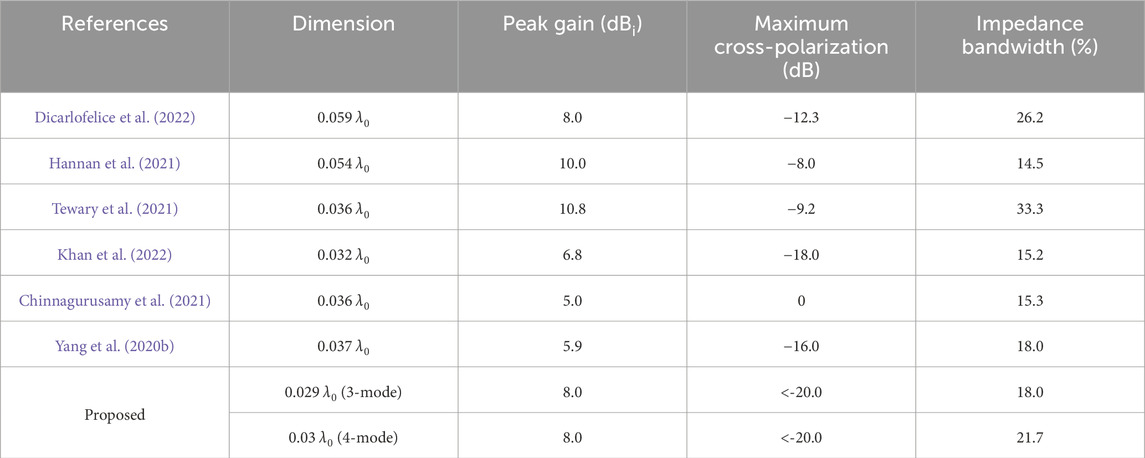
Table 2. Perforamance comparison of the proposed and existing antenna designs.
4 Conclusion
This article designs a low-profile, multi-mode, broadband patch antenna that improves radiation performance. By loading a short-circuit wall on the non-radiating edge of the patch, the E-plane side lobes of the antenna radiation pattern are reduced, effectively reducing the H-plane cross-polarization. By adjusting the number and position of the pins, the size and position of the opening slit, and the width of the patch antenna, we further introduced the three-mode patch antenna based on TM1/2,0, TM3/2,0 and TMRS made by predecessors. In TM1/2,2 mode, a four-mode low-profile broadband patch antenna is designed, which achieves an operating bandwidth of 21.7% with a thickness of only 0.03λ0.
Data availability statement
The original contributions presented in the study are included in the article/Supplementary material, further inquiries can be directed to the corresponding authors.
Author contributions
JT: Conceptualization, Formal Analysis, Resources, Writing–original draft. DA: Software, Validation, Methodology, Resources, Writing–review and editing. IK: Conceptualization, Project administration, Supervision, Visualization, Writing–original draft. P-CW: Investigation, Methodology, Validation, Resources, Writing–review and editing. DM: Funding acquisition, Investigation, Methodology, Project administration, Resources, Supervision, Writing–review and editing.
Funding
The author(s) declare financial support was received for the research, authorship, and/or publication of this article. This work was supported by Princess Nourah bint Abdulrahman University Researchers Supporting Project number (PNURSP2024R435), Princess Nourah bint Abdulrahman University, Riyadh, Saudi Arabia.
Conflict of interest
The authors declare that the research was conducted in the absence of any commercial or financial relationships that could be construed as a potential conflict of interest.
Publisher’s note
All claims expressed in this article are solely those of the authors and do not necessarily represent those of their affiliated organizations, or those of the publisher, the editors and the reviewers. Any product that may be evaluated in this article, or claim that may be made by its manufacturer, is not guaranteed or endorsed by the publisher.
References
Beguad, X., Lepage, A., Varault, S., Soiron, M., and Barka, A. (2018). Ultra-wideband and wide-angle microwave metamaterial absorber. Materials 11 (10), 1–14. doi:10.3390/ma11102045
Cao, K., Ding, H., Li, W., Lv, L., Gao, M., Gond, G., et al. (2022). On the ergodic secrecy capacity of intelligent reflecting surface aided wireless powered communication systems. IEEE Wirel. Commun. Lett. 11 (11), 2275–2279. doi:10.1109/lwc.2022.3199593
Cao, K., Wang, B., Ding, H., Lv, L., Tian, J., Hu, H., et al. (2021). Achieving reliable and secure communications in wireless-powered NOMA systems. IEEE Trans. Veh. Technol. 70 (2), 1978–1983. doi:10.1109/tvt.2021.3053093
Chen, B., Hu, J., Zhao, Y., and Ghosh, B. (2022a). Finite-time observer based tracking control of uncertain heterogeneous underwater vehicles using adaptive sliding mode approach. Sci. China Inf. Sci. 481, 322–332. doi:10.1016/j.neucom.2022.01.038
Chen, B., Hu, J., Zhao, Y., and Ghosh, B. (2022b). Finite-time velocity-free rendezvous control of multiple AUV systems with intermittent communication. IEEE Trans. Syst. Man, Cybern. Syst. 52 (10), 6618–6629. doi:10.1109/tsmc.2022.3148295
Chen, J., Wang, Q., Peng, W., Xu, H., Li, X., and Xu, W. (2022c). Disparity-based multiscale fusion network for transportation detection. IEEE Trans. Intelligent Transp. Syst. 23 (10), 18855–18863. doi:10.1109/tits.2022.3161977
Chinnagurusamy, B., Perumalsamy, M., and Sarasam, A. (2021). Design and fabrication of compact triangular multiband microstrip patch antenna for C- and X-band applications. Int. J. Commun. Syst. 34 (15), 115–123. doi:10.1002/dac.4939
Chung, K., Tian, H., Wang, S., Feng, B., and Lai, G. (2022). Miniaturization of microwave planar circuits using composite microstrip/coplanar-waveguide transmission lines. Alexandria Eng. J. 61 (11), 8933–8942. doi:10.1016/j.aej.2022.02.027
Dai, M., Luo, L., Ren, J., Yu, H., and Sun, G. (2022). PSACCF: prioritized online slice admission control considering fairness in 5G/B5G networks. IEEE Trans. Netw. Sci. Eng. 9 (6), 4101–4114. doi:10.1109/tnse.2022.3195862
Dai, M., Sun, G., Yu, H., and Niyato, D. (2023). Maximize the long-term average revenue of network slice provider via admission control among heterogeneous slices. IEEE/ACM Trans. Netw. 32 (1), 1–16. doi:10.1109/tnet.2023.3297883
Dicarlofelice, A., Digiampaolo, E., and Tognolatti, P. (2022). A numerical procedure to design a UWB aperture-coupled microstrip antenna suitable for space applications. Appl. Sci. 12 (21), 11243–11315. doi:10.3390/app122111243
Dong, J., Ma, Y., Li, Z., and Mo, J. (2021). A miniaturized quad-stopband frequency selective surface with convoluted and interdigitated stripe based on equivalent circuit model analysis. Micromachines 12 (9), 1027–1117. doi:10.3390/mi12091027
Fan, Y., Wang, J., Li, Y., Zhang, J., Qu, S., Han, Y., et al. (2018). Frequency scanning radiation by decoupling spoof surface plasmonpolaritons via phase gradient metasurface. IEEE Trans. Antennas Propag. 66 (1), 203–208. doi:10.1109/tap.2017.2767625
Fang, Z., Wang, J., Liang, J., Yan, Y., Pi, D., Zhang, H., et al. (2023). Authority allocation strategy for shared steering control considering human-machine mutual trust level. IEEE Trans. Intelligent Veh. 9, 1–14. doi:10.1109/tiv.2023.3300152
Farooq, U., Iftikhar, A., Shafique, M., Khan, M., Fida, A., Mughal, M. J., et al. (2021). C-band and X-band switchable frequency-selective surface. Electronics 10 (4), 476–518. doi:10.3390/electronics10040476
Gao, G., Yang, C., Hu, B., Zhang, R. F., and Wang, S. F. (2019). A wide bandwidth wearable all-textile PIFA with dual resonance modes for 5-GHz WLAN applications. IEEE Trans. Antennas Propag. 67 (6), 4206–4211. doi:10.1109/tap.2019.2905976
Gao, J., Wu, D., Yin, F., Kong, Q., Xu, L., and Cui, S. (2023). MetaLoc: learning to learn wireless localization. IEEE J. Sel. Areas Commun. 41 (12), 3831–3847. doi:10.1109/jsac.2023.3322766
Ge, S., Zhang, Q., Chiu, C., Chen, Y., and Murch, R. D. (2018). Single side scanning surface waveguide leaky-wave antenna using spoof surface plasmon excitation. IEEE Access 6, 66020–66029. doi:10.1109/access.2018.2879086
Hannan, S., Islam, M., Faruque, M., and Rmili, H. (2021). Polarization-independent perfect metamaterial absorber for C, X and, Ku band applications. J. Mater. Res. Technol. 15 (5), 3722–3732. doi:10.1016/j.jmrt.2021.10.007
Hao, Z., Zhang, J., and Zhao, L. (2019). A compact leaky-wave using a planar spoof surface plasmonpolariton structure. Int. J. RF Microw. Computer-Aided Eng. 29 (5), 1–7. doi:10.1002/mmce.21617
Hu, J., Wu, Y., Li, T., and Ghosh, B. (2019). Consensus control of general linear multiagent systems with antagonistic interactions and communication noises. IEEE Trans. Automatic Control 64 (5), 2122–2127. doi:10.1109/tac.2018.2872197
Huang, X., and Liu, Z. (2023). Low-cost w-band dual-mode SIW bandpass filters using commercially available printed-circuit-board technology. Electronics 12 (17), 3624–3715. doi:10.3390/electronics12173624
Huang, X., Zhang, X., Zhou, L., Xu, J., and Mao, J. (2023). Low-loss self-packaged Ka-band LTCC filter using artificial multimode SIW resonator. IEEE Trans. Circuits Syst. II Express Briefs 70 (2), 451–455. doi:10.1109/tcsii.2022.3173712
Huang, X., Zhou, L., Volkel, M., Hagelauer, A., Mao, J., and Weigel, R. (2018). Design of a novel quarter-mode substrate-integrated waveguide filter with multiple transmission zeros and higher mode suppressions. IEEE Trans. Microw. Theory Tech. 66 (12), 5573–5584. doi:10.1109/tmtt.2018.2879087
Jannat, M., Islam, M., Yang, S., and Liu, H. (2023). Efficient wi-fi-based human activity recognition using adaptive antenna elimination. IEEE Access 11, 105440–105454. doi:10.1109/access.2023.3320069
Jian, R., Chen, Y., and Chen, T. (2020). A low-profile wideband PIFA based on radiation of multi-resonant modes. IEEE Antennas Wirel. Propag. Lett. 19 (4), 685–689. doi:10.1109/lawp.2020.2976670
Jiang, Y., and Li, X. (2022). Broadband cancellation method in an adaptive co-site interference cancellation system. Int. J. Electron. 109 (5), 854–874. doi:10.1080/00207217.2021.1941295
Jiang, Y., Liu, S., Li, M., Zhao, N., and Wu, M. (2022). A new adaptive co-site broadband interference cancellation method with auxiliary channel. Digital Commun. Netw., 1–16. doi:10.1016/j.dcan.2022.10.025
Jiang, Z., and Xu, C. (2023). Disrupting the technology innovation efficiency of manufacturing enterprises through digital technology promotion: an evidence of 5G technology construction in China. IEEE Trans. Eng. Manag. 71, 1–11. doi:10.1109/tem.2023.3261940
Karami, F., Boutayeb, H., Elahi, A., Ghayekhloo, A., and Talbi, L. (2022). Developing broadband microstripe patch antennas fed by SIW feeding network for spatially low cross-polarization. Sensors 22 (9), 1–14. doi:10.3390/s22093268
Khan, I., Wu, Q., Ullah, I., Rahman, S., Ullah, H., and Zhang, K. (2022). Designed circularly polarized two-port microstrip MIMO antenna for WLAN applications. Appl. Sci. 12 (3), 1068–1114. doi:10.3390/app12031068
Koutinos, A., Kyriacou, G., Volakis, J., and Chryssomallis, M. (2022). Bandwidth enhancement of antennas designed by band-pass filter synthesis due to frequency pulling techniques. IET Microwaves, Antennas Propag. 16 (1), 1–17. doi:10.1049/mia2.12206
Kumar, C., Raghuwanshi, S., and Kumar, V. (2022). Graphene based microstrip patch antenna on photonic crystal substrate for 5G application. Front. Mater. 9, 1–11. doi:10.3389/fmats.2022.1079588
Kumar, N., Naidu, K., Banerjee, P., Babu, T., and Reddy, B. (2021). A review on metamaterials for device applications. Crystals 11 (5), 1–16. doi:10.3390/cryst11050518
Lan, G., Tang, L., Dong, J., Nong, J., Luo, P., Li, X., Wei, W., et al. Enhanced asymmetric light-plasmon coupling in graphene nanoribbons for high-efficiency transmissive infrared modulation,” Laser and Photonics Rev., 18, 1, 2300469, 1–11. 2024, doi:10.1002/lpor.202300469
Lee, D., Kim, K., and Pyo, S. (2019). Mesh-grounded monopolar hexagonal microstrip antenna for artillery-launched observation round. Electronics 8 (11), 1279–1315. doi:10.3390/electronics8111279
Li, A., Masouros, C., Swindlehurst, A., and Yu, W. (2021b). 1-Bit massive MIMO transmission: embracing interference with symbol-level precoding. IEEE Commun. Mag. 59 (5), 121–127. doi:10.1109/mcom.001.2000601
Li, M., Wang, T., Chu, F., Han, Q., Qin, Z., and Zuo, M. (2021a). Scaling-basis chirplet transform. IEEE Trans. Industrial Electron. 68 (9), 8777–8788. doi:10.1109/tie.2020.3013537
Liu, D., Cao, Z., Jiang, H., Zhou, S., Xiao, Z., and Zeng, F. (2022). Concurrent low-power listening: a new design paradigm for duty-cycling communication. ACM Trans. Sens. Netw. 19 (1), 1–24. doi:10.1145/3517013
Liu, G. (2021). Data collection in MI-assisted wireless powered underground sensor networks: directions, recent advances, and challenges. IEEE Commun. Mag. 59 (4), 132–138. doi:10.1109/mcom.001.2000921
Liu, L., Wang, J., Yin, X., and Chen, Z. (2018a). Wide-angle beam scanning leaky-wave antenna using spoof surface plasmonpolaritons structure. Electronics 7 (12), 348–415. doi:10.3390/electronics7120348
Liu, N., Lei, Z., Fu, G., and Liu, Y. (2018b). A low profile shorted-patch antenna with enhanced bandwidth and reduced H-plane cross-polarization. IEEE Trans. Antennas Propag. 66 (10), 5602–5607. doi:10.1109/tap.2018.2855730
Liu, N., Zhu, L., and Choi, W. (2017b). A low-profile wide-bandwidth planar inverted-F antenna under dual resonances: principle and design approach. IEEE Trans. Antennas Propag. 65 (10), 5019–5025. doi:10.1109/tap.2017.2736578
Liu, N., Zhu, L., Choi, W., and Zhang, X. (2017a). A low-profile aperture coupled microstrip antenna with enhanced bandwidth under dual resonance. IEEE Trans. Antennas Propag. 65 (3), 1055–1062. doi:10.1109/tap.2017.2657486
Lu, H., Liu, F., Su, M., and Liu, Y. (2018). Design and analysis of wideband U-slot patch antenna with U-shaped parasitic elements. Int. J. RF Microw. Computer-Aided Eng. 28 (2), e21202–e21213. doi:10.1002/mmce.21202
Lu, J., and Osorio, C. (2018). A probabilistic traffic-theoretic network loading model suitable for large-scale network analysis. Transp. Sci. 52 (6), 1509–1530. doi:10.1287/trsc.2017.0804
Lu, W., Qing, L., Wang, S., and Zhu, L. (2017). Design approach to a novel dual-mode wideband circular sector patch antenna. IEEE Trans. Antennas Propag. 65 (10), 4980–4990. doi:10.1109/tap.2017.2734073
Ma, K., Li, Z., Liu, P., Yang, J., Geng, Y., Yang, B., et al. (2021). Reliability-constrained throughput optimization of industrial wireless sensor networks with energy harvesting relay. IEEE Internet Things J. 8 (17), 13343–13354. doi:10.1109/jiot.2021.3065966
Mao, Y., Sun, R., Wang, J., Cheng, Q., Kiong, L., and Ochieng, W. (2022a). New time-differenced carrier phase approach to GNSS/INS integration. GPS Solutions 26 (4), 122–215. doi:10.1007/s10291-022-01314-3
Mao, Y., Zhu, Y., Tang, Z., and Chen, Z. (2022b). A novel airspace planning algorithm for cooperative target localization. Electronics 11 (18), 2950–3016. doi:10.3390/electronics11182950
Min, H., Lei, X., Wu, X., Fang, Y., Chen, S., Wang, W., et al. “Toward interpretable anomaly detection for autonomous vehicles with denoising variational transformer,” Eng. Appl. Artif. Intell., 129, 107601, 2024, 1–16. doi:10.1016/j.engappai.2023.107601
Min, H., Li, Y., Wu, X., Wang, W., Chen, L., and Zhao, X., “A measurement scheduling method for multi-vehicle cooperative localization considering state correlation,” Veh. Commun., 44, 100682, 2023. 1–14. doi:10.1016/j.vehcom.2023.100682
Sharaf, M., Zaki, A., Hamad, R., and Omar, M. (2020). A novel dual-band (38/60 GHz) patch antenna for 5G mobile handsets. Sensors 20 (9), 2541–2615. doi:10.3390/s20092541
Soliman, S., Eldesouki, E., and Attiya, A. (2022). Analysis and design of an X-band reflectarray antenna for remote sensing satellite system. Sensors 22 (3), 1166–1223. doi:10.3390/s22031166
Srivastava, H., Singh, A., Rajeev, A., and Tiwari, U. (2020). Bandwidth and gain enhancement of rectangular microstrip patch antenna (RMPA) using slotted array technique. Wirel. Personal. Commun. 114 (3), 699–709. doi:10.1007/s11277-020-07388-x
Subha, T., Subash, T., Jane, K., Devadharshini, D., and Francis, D. (2020). Study and analysis of suppress of surface wave propagation in microstrip patch antenna. Mater. Proc. 24 (4), 2414–2423. doi:10.1016/j.matpr.2020.03.771
Tewary, T., Maity, S., Mukherjee, S., Roy, A., Sarkar, P., and Bhunia, S. (2021). Design of high gain broadband microstrip patch antenna for UWB/X/Ku band applications. AEU-International J. Electron. Commun. 139 (7), 153905–153913. doi:10.1016/j.aeue.2021.153905
Ullah, S., Ruan, C., Haq, T., and Zhang, X. (2019). High performance THz patch antenna using photonic band gap and defected ground structure. J. Electromagn. Waves Appl. 33 (15), 1943–1954. doi:10.1080/09205071.2019.1654929
Wang, Q., Li, P., Rocca, P., Li, R., Tang, G., Hu, N., et al. (2023). Interval-based tolerance analysis method for petal reflector antenna with random surface and deployment errors. IEEE Trans. Antennas Propag. 71 (11), 8556–8569. doi:10.1109/tap.2023.3314097
Wen, C., Huang, Y., Zheng, L., Liu, W., and Davidson, T. (2023). Transmit waveform design for dual-function radar-communication systems via hybrid linear-nonlinear precoding. IEEE Trans. Signal Process. 71, 2130–2145. doi:10.1109/tsp.2023.3278858
Wu, Z., Lu, W., Yu, J., and Zhu, L. (2020). Wideband null frequency scanning circular sector patch antenna under triple resonance. IEEE Trans. Antennas Propag. 68 (11), 7266–7274. doi:10.1109/tap.2020.2995459
Xu, B., Wang, X., Zhang, J., Guo, Y., and Razzaqi, A. (2022). A novel adaptive filtering for cooperative localization under compass failure and non-Gaussian noise. IEEE Trans. Veh. Technol. 71 (4), 3737–3749. doi:10.1109/tvt.2022.3145095
Xu, G., Zhang, Q., Song, Z., and Ai, B. (2023a). Relay-assisted deep space optical communication system over coronal fading channels. IEEE Trans. Aerosp. Electron. Syst. 59 (6), 8297–8312. doi:10.1109/taes.2023.3301463
Xu, H., Han, S., Li, X., and Han, Z. (2023c). Anomaly traffic detection based on communication-efficient federated learning in space-air-ground integration network. IEEE Trans. Wirel. Commun. 22 (12), 9346–9360. doi:10.1109/twc.2023.3270179
Xu, P., Lan, D., Wang, F., and Shin, I. (2023b). In-memory computing integrated structure circuit based on non-volatile flash memory unit. Electronics 12 (14), 3155–3214. doi:10.3390/electronics12143155
Yang, D., Zhai, H., Guo, C., and Li, H. (2020b). A compact single-layer wideband microstrip antenna with filtering performance. IEEE Antennas Wirel. Propag. Lett. 19 (5), 801–805. doi:10.1109/lawp.2020.2980631
Yang, H., Chen, D., Mao, Y., and Yang, J. (2020a). Tunable broadband THz waveband absorbers based on graphene for digital coding. Nanomaterials 10 (9), 1844–1917. doi:10.3390/nano10091844
Yang, M., Cai, C., Wang, D., Wu, Q., Liu, Z., and Wang, Y. (2023b). Symmetric differential demodulation-based heterodyne laser interferometry used for wide frequency-band vibration calibration. IEEE Trans. Industrial Electron. 71 (6), 1–9. doi:10.1109/tie.2023.3299015
Yang, Y., Zhang, Z., Zhou, Y., Wang, C., and Zhu, H. (2023a). Design of a simultaneous information and power transfer system based on a modulating feature of magnetron. IEEE Trans. Microw. Theory Tech. 71 (2), 907–915. doi:10.1109/tmtt.2022.3205612
Yin, Y., Guo, Y., Su, Q., and Wang, Z. (2022). Task allocation of multiple unmanned aerial vehicles based on deep transfer reinforcement learning. Drones 6 (8), 215–15. doi:10.3390/drones6080215
Zhang, H., Wu, H., Jin, H., and Li, H. (2023a). High-dynamic and low-cost sensorless control method of high-speed brushless DC motor. IEEE Trans. Industrial Inf. 19 (4), 5576–5584. doi:10.1109/tii.2022.3196358
Zhang, Y., Zhao, P., Lu, Q., Zhang, Y., Lei, H., Yu, C., et al. Functional additive manufacturing of large-size metastructure with efficient electromagnetic absorption and mechanical adaptation,” Compos. Part A Appl. Sci. Manuf., 173, 2023b, 1–14. doi:10.1016/j.compositesa.2023.107652
Zhou, G., Xu, C., Zhang, H., Zhou, X., Zhao, D., Wu, G., et al. (2022a). PMT gain self-adjustment system for high-accuracy echo signal detection. Int. J. Remote Sens. 43 (19-24), 7213–7235. doi:10.1080/01431161.2022.2155089
Keywords: microstrip patch, antenna design, waveguide, resonator, beamform
Citation: Tiang JJ, Alsekait DM, Khan I, Wang P-C and Madsen DØ (2024) Design of novel microstrip patch antenna for millimeter-wave B5G communications. Front. Mater. 11:1364159. doi: 10.3389/fmats.2024.1364159
Received: 01 January 2024; Accepted: 16 February 2024;
Published: 04 April 2024.
Edited by:
Muhammad Danang Birowosuto, Łukasiewicz Research Network–PORT Polish Center for Technology Development, PolandReviewed by:
Kemal Gokhan Nalbant, Beykent University, TürkiyeJosé Escorcia-Gutierrez, Costa University Corporation, Colombia
Copyright © 2024 Tiang, Alsekait, Khan, Wang and Madsen. This is an open-access article distributed under the terms of the Creative Commons Attribution License (CC BY). The use, distribution or reproduction in other forums is permitted, provided the original author(s) and the copyright owner(s) are credited and that the original publication in this journal is cited, in accordance with accepted academic practice. No use, distribution or reproduction is permitted which does not comply with these terms.
*Correspondence: Deema Mohammed Alsekait, dmalskait@pnu.edu.sa; Pi-Chung Wang, pcwang@nchu.edu.tw; Dag Øivind Madsen, dag.oivind.madsen@usn.no