Investigation into the seamless construction for hundred-meter scale super-length raft structure based on magnesia expansive agent concrete
 Bin Han
  Hong Liao
- China Construction Third Engineering Bureau Group Co., Ltd., Chongqing, China
This research introduces an innovative construction method based on magnesia expansive agent concrete for the seamless construction of hundred-meter scale super-length raft structures, corroborated by the on-site test. The basic principle of this construction method is to use the pre compression stress generated by magnesia expansive agent to offset temperature and shrinkage stress. A temperature-strain monitoring system was employed to gather data, affirming the technique’s applicability and safety. Through the examination of temperature and strain dispersion trends in super-length raft structure, recommendations for the configuration of temperature-strain sensors have been put forth. Through the scrutiny of the temporal evolution pattern of temperature, the specific temporal and spatial coordinates that warrant particular vigilance during the surveillance of the raft’s inner-surface temperature difference were identified. Upon evaluating the correlation between strain dispersion and strain-temperature differential in the raft’s thickness dimension, a novel temperature control index (the bottom-surface temperature difference) was introduced. The threshold for this metric was established at 30°C, derived from empirical test outcomes conducted on-site. Furthermore, the critical regions for monitoring the bottom-surface temperature difference were specified.
1 Introduction
Within the realm of contemporary construction engineering, the utilization of mass concrete edifices is progressively pervasive, encompassing the raft foundations of ultra-tall structures, piers of substantial bridges, dams, and so forth (Ming et al., 2022). Owing to the considerable structural dimensions and the immense quantity of concrete casting associated with these projects, a multitude of challenges frequently arise during the construction phase, one notable issue being the formation of thermal cracks (Xin et al., 2021).
Throughout the solidification phase, mass concrete engenders a substantial quantity of heat as a result of the exothermic hydration reaction of cement (Liu et al., 2022). If this heat is not dispersed promptly, it will instigate a swift escalation in the internal temperature of the concrete. Nevertheless, due to the concrete surface being in contact with the environment, its heat dissipation rate is accelerated, thereby establishing a temperature gradient with a high internal temperature and a low external temperature. When this temperature disparity surpasses the concrete’s tolerance threshold, thermal stress will be induced within the concrete, culminating in the emergence of thermal cracks. The manifestation of these thermal cracks could gravely compromise the safety and durability of the concrete structures (Tatro et al., 2007).
Furthermore, shrinkage stress constitutes a significant concern during the preservation procedure of super-length concrete structures. Concrete undergoes contraction throughout the solidification process. When the contraction process of concrete is restricted, shrinkage stress is engendered within the structure, and the elongation of the structure directly correlates with the magnitude of the shrinkage stress (Jin, 2002). If this shrinkage stress surpasses the tensile resilience of the concrete, it will instigate the concrete to fracture, resulting in the formation of shrinkage cracks.
Super-length raft structures are classified under both mass concrete structures and super-length structures. Consequently, the effective management of their thermal cracks and shrinkage cracks is a crucial challenge that necessitates resolution in the contemporary realm of construction engineering. This issue has been the subject of investigation by scholars from diverse nations.
An automated preservation apparatus was devised to address the issue of thermal cracks during the construction of mass concrete (Ha et al., 2014). This apparatus maintains the temperature gradient between the internal and external milieu of the edifice beneath a specified threshold, and it has been efficaciously examined in simulations and field implementations.
An investigation into the influence of cement and aggregate varieties on the hydration temperature and mechanical attributes of concrete was conducted (Batog and Giergiczny, 2014). They employed six varieties of cement and four types of aggregates. The findings indicated that low-clinker cement can markedly diminish the hydration temperature of concrete, thereby mitigating the likelihood of fissure development. While the type of aggregate does not impact the hydration temperature, it can influence the magnitude of thermal stress due to varying thermal expansion coefficients.
A case study on the construction of mass concrete bridge foundations in Iowa, USA, with an emphasis on averting the emergence of thermal cracks was conducted (by Sargam et al., 2019). They employed ConcreteWorks software to prognosticate the thermal performance of the edifice. The forecasted temperature evolution curves and temperature disparities were juxtaposed with the real-time measurements of the bridge foundation, demonstrating a commendable match. They also executed a sensitivity analysis of various mass concrete parameters.
A framework utilizing a Distributed Temperature Sensing (DTS) system to regulate cracks in mass concrete edifices in reservoir ventures was proposed (Ouyang et al., 2019). The DTS system is employed to monitor the temperature of the concrete, and the thermal performance of the cast-in-place concrete is ascertained through a reverse analysis technique. Subsequently, the risk of concrete cracking under diverse construction and environmental conditions is prognosticated and evaluated.
A nonlinear incremental structural analysis of mass concrete was performed (Truman et al., 1991), taking into account thermal effects, to assess the impact of creep, shrinkage, adiabatic temperature rise, and the construction process on tensile stress. The findings indicated that mass concrete edifices are susceptible to cracking. The paper furnished stress and strain time-history diagrams at typical locations of mass concrete, underscoring the importance of these diagrams in determining the impact of the construction sequence.
The pivotal issue of the spacing between post-pouring strips in mass concrete edifices was investigated (Zhou et al., 2019). The research centered on a 100 m long inverted T-shaped concrete edifice on a soft soil foundation in the Yangtze River Delta region. They utilized the finite element method to simulate the temperature and stress field of the concrete under various construction conditions, and proffered recommended spacing for the post-pouring strips.
However, extant research has not been successful in accomplishing the seamless construction of hundred-meter scale super-length raft structures. The conventional construction methodologies of super-length raft structures predominantly encompass the “Sequential Placement Method” and the “Post Pouring Strip Method.” The former method partitions the extensive concrete blocks into multiple smaller units for phased construction during the initial stage of high-temperature shrinkage stress. Following a brief period of stress alleviation, these smaller units are amalgamated into a single entity during the subsequent stage of reduced shrinkage stress, leveraging the tensile strength of the concrete to counteract the temperature and shrinkage stress of the ensuing stage. The specific construction sequence involves pouring the initial batch, followed by the second batch after a minimum interval of 7 days. This approach capitalizes on the inherent principle that the performance of concrete remains unstable during the initial 5–10 days, facilitating the easy release of internal stress prior to complete solidification. However, the compartment length in the “Sequential Placement Method” should not surpass 40 m (Ministry of Housing and Urban Rural Development of the People’s Republic of China, 2023). For super-length raft structures, it necessitates the division and pouring of multiple compartments multiple times, leading to an extended construction period and intricate construction organization design. The “Post Pouring Strip Method” involves the creation of temporary construction joints at corresponding locations, temporarily segregating the structure into several sections, shrinking the internal components, and pouring and compacting the concrete of the construction joint after a certain duration, thereby integrating the structure as a whole. Nevertheless, the interface between the new and old concrete at the construction joint is susceptible to quality issues such as cracking and water seepage, and the construction joint necessitates secondary pouring, which prolongs the construction period and hampers the construction progress.
To address these issues, this paper introduces a seamless construction method for hundred-meter scale super-length raft structures predicated on expansive strengthening bands. The basic principle of this construction method is to use the pre compression stress generated by magnesia expansive agent to offset temperature and shrinkage stress. Magnesium oxide (MgO), characterized by its white, powdery form, exhibits significant hygroscopic and expansive properties. When incorporated into concrete as an expansion agent, it absorbs the inherent moisture, leading to an expansion of the MgO and the generation of a specific pressure. A chemical interaction between MgO and water results in the formation of magnesium hydroxide (Mg(OH)2). The resultant Mg(OH)2 occupies a volume that is 3–4 times greater than the initial MgO, facilitating the expansion of the material.
In contrast to the conventional technique, this construction method circumvents secondary construction and independent support, thereby diminishing construction expenses and abbreviating the construction duration. The primary limitation of this construction method is that the induction of preloading stress is contingent upon the expansion rate and the interstitial distance of the expansive strengthening band. The expansion rate of the concrete within the expansive strengthening band is capped at 0.8% (Li et al., 2021). If the expansion rate surpasses this threshold, the alterations in porosity induced by expansion can compromise the mechanical attributes and longevity of the concrete. Consequently, the spacing of the expansive strengthening band is also subject to an upper limit. Leveraging a construction venture of the China Construction Third Engineering Bureau Group Co., Ltd., an on-site test was executed on a raft structure that spans 130 m in length and varies from 1.9 m to 3.55 m in thickness. A temperature-strain monitoring system was employed to monitor the raft concrete, substantiating the practicability and safety of this construction method.
2 Materials and methods
2.1 Project overview
The construction venture encompasses an region of 186,000 m2, with the cumulative edifice region amounting to 563,000 m³. The tower of the project employs a raft foundation, with its load-bearing stratum situated in the middle weathered mudstone, and the characteristic value of the foundation load-bearing capacity is 1,205 kPa. Notably, the tower raft of the A, B, and C edifices of the hospital is super-length, with a raft thickness of 1900 mm, and at the elevator and catchment well pit, the maximal thickness of the raft escalates to 3,550 mm. The length of the raft extends to about 130 m at its longest, and the width ranges between 25–34 m. The dimensions of the raft and the large sample of the elevator and catchment well pit are depicted in Figure 1.
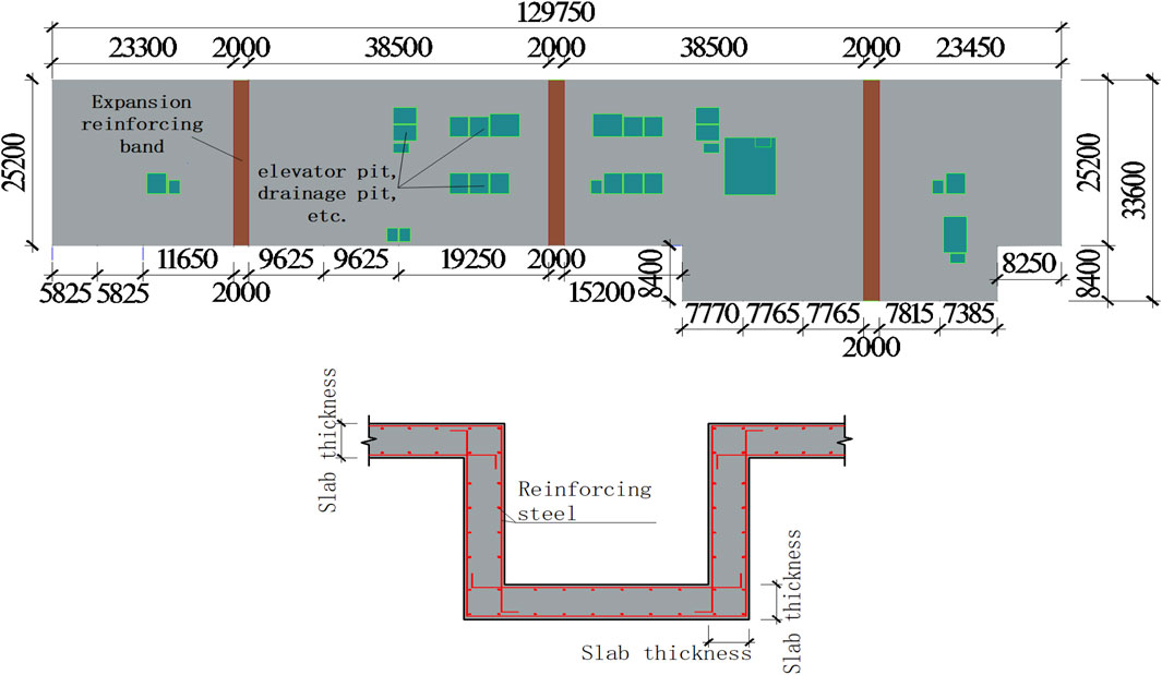
Figure 1. Dimensional drawing of the raft and the elevator, catchment well pit (unit mm).
The raft was fabricated with C35 concrete, and 3 expansive strengthening bands were incorporated into the raft. The concrete grade of the expansive strengthening band was designated as C40, and a MgO expansion agent was integrated. The mix proportion and compressive strength at varying ages (7-day and 28-day) of C35 and C40 concrete are illustrated in Supplementary Tables S1, S2. For the sake of differentiation, the raft exterior to the expansive strengthening band was denoted as the “standard region.” The expansive strengthening band and the raft concrete were cast concurrently, accomplishing the seamless construction of the hundred-meter scale super-length raft, as depicted in Figure 2.
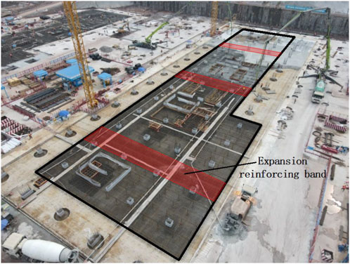
Figure 2. On-site casting diagram of the raft.
In the conventional methodology for seamless construction of super-length structures, calcium sulfoaluminate (Ca4Al6SO16) and calcium oxide (CaO) serve as the primary expansion agents. The underlying principle of expansion involves hydration, leading to the formation of ettringite and calcium hydroxide. However, this approach exhibits several limitations: under standard temperature and water curing conditions, the expansion reaction culminates within a span of 7 days, rendering it incapable of compensating for subsequent shrinkage; the initial expansion rate is excessively rapid, and the plastic stage depletes a significant amount of expansion energy, thereby posing challenges in compensating for the shrinkage due to temperature drop and subsequent drying of concrete; the expansion products, namely calcium hydroxide and ettringite, exhibit a solubility of 0.17 g/100 g for calcium hydroxide at room temperature, while ettringite decomposes above 80°C.
To address the issues associated with traditional expansion agents, this construction technique innovatively incorporates MgO expansion agents into the seamless construction of super-length structures. The principle of expansion, as elucidated in the preceding chapter, endows MgO expansion agents with several advantages: they offer the flexibility to regulate the expansion characteristics of concrete through various combinations of dosages and activities, thereby synchronizing the expansion energy with concrete shrinkage; it allows for the customization of product types based on environmental conditions, controls the pattern of expansion and development, and compensates for self-shrinkage, temperature shrinkage, and drying shrinkage throughout the entire cycle, thereby achieving superior resistance to cracking and seepage; the expansion is conspicuous, and the solubility of the product is extremely low. The expansion product is Mg(OH)2, with a solubility of 0.0009 g/100 g, and its expansion performance remains stable at elevated temperatures.
To comprehensively comprehend the efficacy and benefits of the MgO expansion agent, a series of concrete expansion experiments were executed, with the type of expansion agent serving as the variable. The experimental variables for the 3 concrete groups were: absence of an expansion agent, incorporation of a CaO expansion agent, and addition of an MgO expansion agent. The outcomes of these tests are depicted in Figure 3.
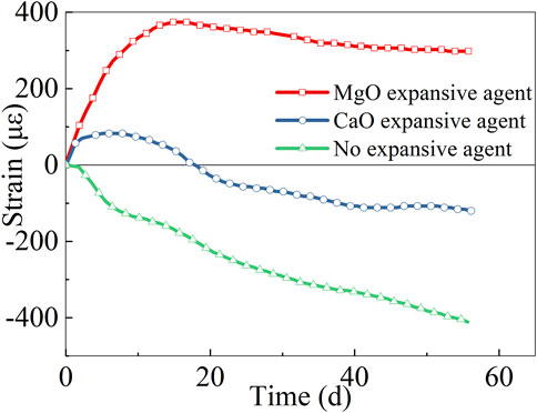
Figure 3. Comparison of the effects of expansion agents.
The graphical representation reveals that the concrete devoid of an expansion agent did not undergo expansion, but initiated contraction subsequent to the initial setting. Concrete supplemented with a CaO expansion agent exhibited substantial expansion during the initial phase, attaining its peak expansion rate on the 8th day, followed by contraction. Conversely, concrete supplemented with an MgO expansion agent demonstrated significant expansion during the initial 17 days. Post this period, the expansion rate experienced a slight decline, yet maintained a relatively elevated level of expansion rate. From the perspective of the “full pouring maintenance cycle” theory, it is evident that the MgO expansion agent possesses significant benefits.
The experimental location was situated in the Jiulongpo District of Chongqing City, with the experimental duration extending from 24 June 2023, to 23 August 2023. Throughout this timeframe, the maximum recorded temperature was 39°C, observed on July 12 and August 11, while the minimum temperature of 20°C was noted on July 14. Predominantly, the wind conditions were classified as first-class, with velocities ranging between 0.3 and 1.5 m/s. The initial experimental design proposed the utilization of wired temperature-strain sensors. However, during the implementation phase, two significant challenges emerged: the extensive length of the raft structure necessitated a substantial quantity of wires, escalating the testing expenses; additionally, the construction process posed a risk of wire damage, leading to potential measurement point failures. To address these issues, the decision was made to employ wireless sensors. Subsequent on-site testing and verification confirmed the efficacy of this solution.
2.2 Temperature-strain monitoring system
2.2.1 Temperature-strain sensor
In this investigation, the SZZX-A150 embedded strain gauge was employed as a temperature-strain sensor, as depicted in Figure 4. This sensor operates on the principle of wire vibration, where a specified length of steel wire is tensioned between two terminal blocks (steel wire clamping pins). The terminal blocks are intimately affixed to the concrete under examination, and the deformation of the concrete can be comprehensively reflected to the two terminal blocks, instigating relative movement between them and leading to alterations in the tension of the steel wire. This shift in tension induces a change in the natural resonance frequency of the steel wire. The instrument quantifies this change in the natural resonance frequency to ascertain the change in stress and strain within the concrete. The standard range of the sensor is ±1,500 με, and the sensitivity is 1 με. Additionally, this sensor utilizes the DS18B20 digital temperature sensor, which can measure the temperature of the measurement point in real time. The applicable temperature range is −20°C–80°C, and the temperature measurement accuracy attains ± 0.5°C.
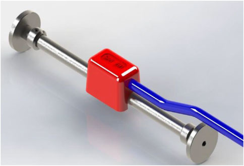
Figure 4. SZZX-A150 embedded strain gauge.
Throughout the embedding procedure, rebar functioned as a support carrier, and the temperature-strain sensor was affixed to the rebar to guarantee that the sensor did not directly interact with the wall panel and the supporting rebar, as illustrated in Figure 5. During the concrete casting procedure, particular care was taken to avoid directly impacting the temperature-strain sensor and the wire; during the tamping procedure, the tamper was strictly prohibited from contacting the sensor and the wire. Throughout the casting procedure, a dedicated individual was assigned for real-time surveillance to ensure the precision and safety of the operation.
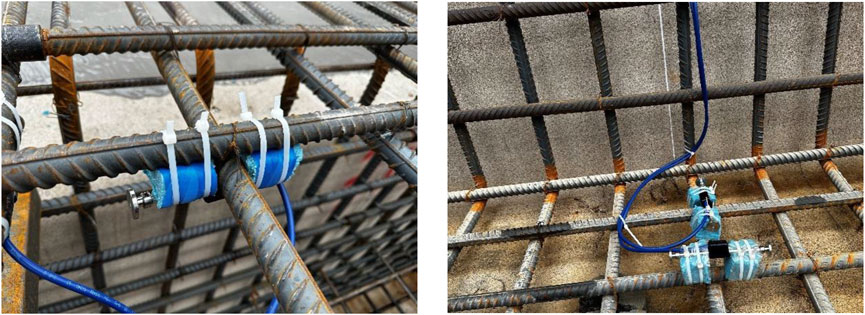
Figure 5. Temperature-strain sensor layout.
2.2.2 Temperature-strain system arrangement
In accordance with the stipulations for temperature monitoring in the “Standard for Construction of Mass Concrete” GB50496-2018 (Ministry of Housing and Urban-Rural Development of the People’s Republic of China, 2018), a total of 123 temperature-strain sensors were systematically positioned within the raft foundation, as depicted in Figure 6. At each designated measurement point, a trio of sensors was arranged in alignment with the thickness of the raft. The uppermost and lowermost measurement points were situated 50 mm from the concrete surface, while the median measurement point was located at the midpoint of the raft thickness.
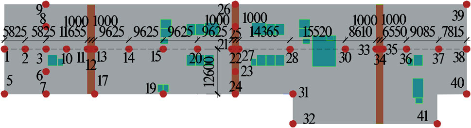
Figure 6. Temperature-strain sensor arrangement (Unit mm).
In alignment with the central axis of the raft in the direction of its length, 21 measurement points were systematically positioned, and they were densified at the expansive strengthening band, with a trio of measurement points arranged at each expansive strengthening band. At a distance of 11.65 m from the leftmost edge of the raft, a quintet of measurement points was arranged in alignment with the width of the raft, and an additional quintet of measurement points was arranged in alignment with the width of the raft at the second expansive strengthening band. Additionally, measurement points were positioned at the corner points of the raft. Prior to the pouring of the concrete, the sensor layout was finalized, the wires were bundled and organized, and ultimately gathered to the data collection chamber.
3 Results and discussions
3.1 Principle of temperature distribution
The temperature distribution along the longitudinal axis of the raft, as depicted in Figure 7, evolved in 3 distinct phases:
1) Thermal accumulation phase: In the initial 48 h post-casting, the temperature of the raft escalated swiftly.
2) Thermal transfer and release phase: From the 72 nd h to the 7th day post-casting, the temperature of the raft progressively declined, with the surface temperature exhibiting the most significant decrease.
3) Thermal balance phase: From the 28th to the 60th day post-casting, the cement hydration reaction was fundamentally complete, and the temperature of the raft exhibited a tendency towards stabilization.
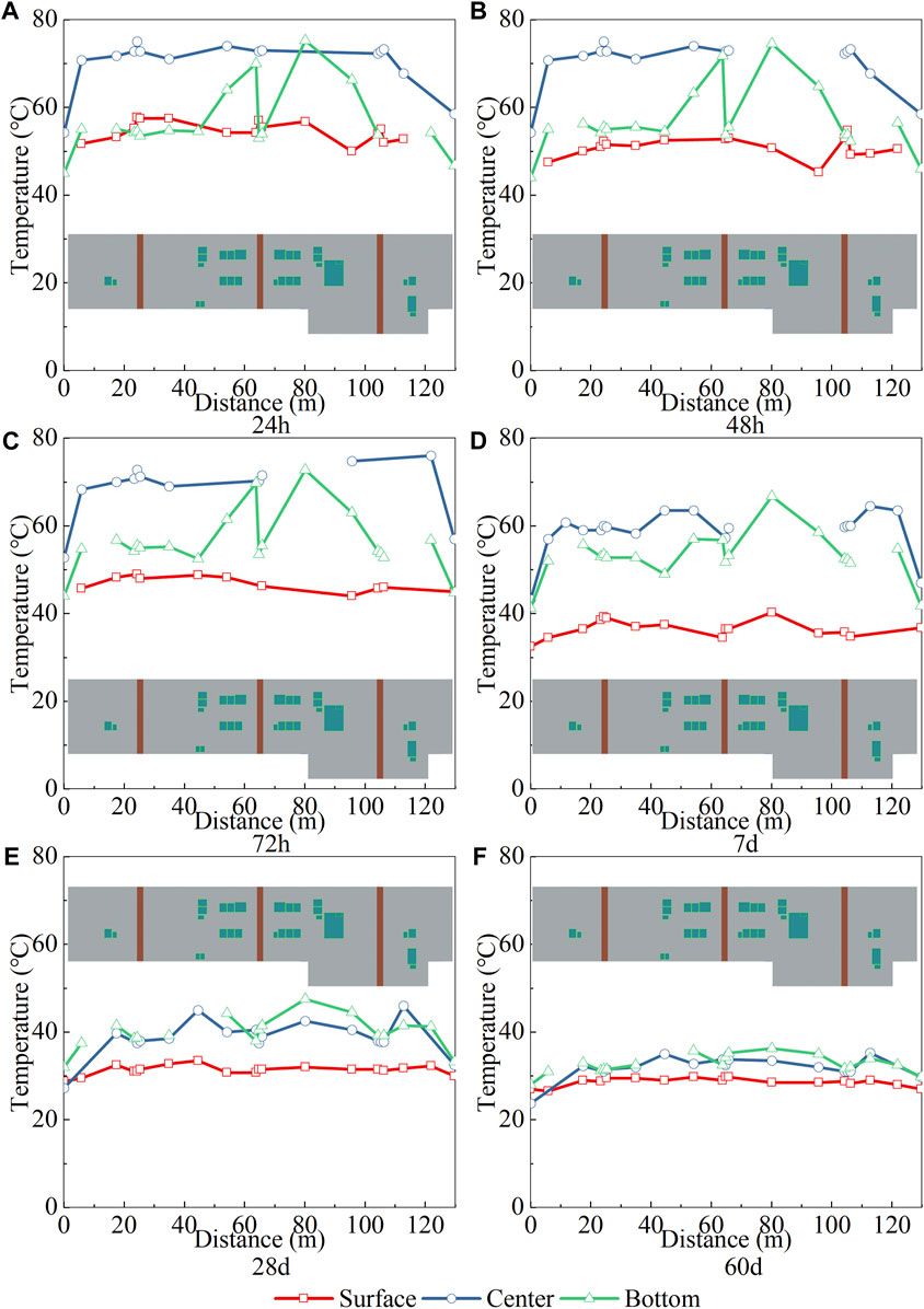
Figure 7. Principle of temperature distribution. (A) 24 h, (B) 48 h, (C) 72 h, (D) 7 d, (E) 28 d, (F) 60 d.
During the thermal accumulation phase, the central temperature exceeded the surface and bottom temperatures. Owing to the relatively suboptimal heat dissipation conditions in the center, an excess of heat accumulated, instigating a rise in temperature (Xie et al., 2023). The surface temperature along the longitudinal axis of the raft exhibited a relatively uniform distribution, but in the 80 m–96 m region, the surface temperature declined by 6.75°C. This region of the surface encompassed a lowering plate region, which might have contributed to this temperature distribution characteristic. The lowering plate region on the surface augmented the contact region with the environment, which might have enhanced the heat dissipation efficiency of the local region. Hence, in the process of architecting a temperature-strain monitoring system, it is imperative to enhance the density of sensors within the surface lowering plate region. This augmentation is crucial to promptly detect alterations in the inner-surface temperature difference.
The central temperature exhibited a distribution characteristic of being elevated in the middle and diminished at both ends along the longitudinal direction, with the middle being approximately 16°C higher than both ends. This phenomenon can be attributed to the larger contact region with the environment at both ends, permitting heat to be dissipated to the environment more rapidly through convection and radiation. In the process of positioning temperature-strain sensors centrally, it is essential to implement encryption at the terminal point of the raft. This measure is crucial to circumvent imprecise monitoring of the inner-surface temperature difference, which could potentially resulted by substantial alterations in the temperature gradient within the central space.
The bottom temperature escalated by approximately 15°C and 20°C respectively at 63.8 m and 80.2 m, which might be associated with the increase in the thickness of the raft in these regions. This alteration in thickness was induced by the layout of the elevator and catchment well pits. In these dense well pit regions, the thickening of the raft caused heat to accumulate in these local regions, thereby causing the temperature to escalate. The temperature gradient in the bottom of the elevator and catchment well pits exhibits considerable spatial variation. To ensure precise measurement of the bottom-surface temperature difference, it is recommended to implement encryption for the temperature-strain sensor situated at the bottom in this specific location.
During the thermal transfer and release phase, the mean temperatures of the surface, center, and bottom declined by 14.3°C, 11.5°C, and 3.6°C, respectively. The pronounced reduction in surface temperature was attributable to the direct interaction of the concrete surface with the external environment, facilitating effective heat dissipation via convection and radiation mechanisms. The elevated heat dissipation efficiency of the surface region was due to its larger surface region and direct interaction with the ambient environment, particularly following the deceleration of the hydration reaction, the temperature decrease was more conspicuous. The larger decline in central temperature indicated that as the hydration reaction decelerated, the accumulated heat commenced conducting outward through the concrete. A pronounced reduction in the raft’s surface temperature engenders a substantial spatial temperature differential between its center and surface. This differential facilitates thermal conduction from the center towards the surface, culminating in a marked diminution of the center temperature. The smaller decline in bottom temperature was attributable to its contact with the foundation, which restricted the heat dissipation from the bottom.
During the thermal balance phase, the mean temperatures of the surface, center, and bottom declined by 7.9°C, 26.8°C, and 20.3°C, respectively. Figure 7F illustrates that at 60 days, the temperatures of the surface, center, and bottom exhibited a tendency towards consistency and proximity to the environmental temperature. This convergence phenomenon reflected the gradual establishment of thermal equilibrium, indicating that the heat exchange between various parts inside the concrete reached a balanced state, rendering the temperature distribution of the entire structure to be uniform (Yang et al., 2022). In addition, the heat exchange between the raft and its surrounding environment also reached a dynamic balance, causing the concrete temperature to be close to the environmental temperature, indicating that the hydration heat of the concrete was entirely over.
3.2 Principle of strain distribution
The strain distribution along the longitudinal axis of the raft, as depicted in Figure 8, was predominantly instigated by temperature fluctuations during the thermal accumulation phase (Liu et al., 2020). As discernible from Section 3.1, the temperature in the central region was typically superior to the surface and bottom, inducing a more pronounced expansion of its concrete volume. However, this expansion was restrained, culminating in a maximum compressive strain of −560 με in the central region. The mean compressive strain in the central region was 282 με and 223 με greater than the surface and bottom, respectively.
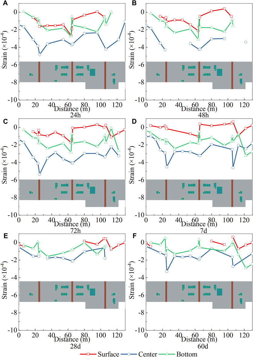
Figure 8. Principle of strain distribution. (A) 24 h, (B) 48 h, (C) 72 h, (D) 7 d, (E) 28 d, (F) 60 d.
In the vicinity of the expansive strengthening band, a substantial escalation in compressive strain was observed in the surface, center, and bottom regions of the concrete. This phenomenon can be ascribed to two primary factors: Firstly, due to the superior grade of concrete in the expansive strengthening band, the quantity of heat engendered by hydration is elevated (Wang et al., 2022), which significantly escalates the temperature in this region, leading to a higher degree of thermal expansion. Secondly, the MgO expander induces the concrete in the expansive strengthening band to expand (Tian et al., 2022), which is restrained by the adjacent standard region concrete, resulting in compressive strain (Myint et al., 2021).
Within the 63.8 m–96 m region, the strain on the surface of the structure exhibited a shift from −265 με to 4 με, a total increment of 269 με, as shown in Figure 8A. In contrast, the strain in the bottom region declined from −52 με to −224 με, a total decrement of 172 με. The rationale for this strain distribution pattern can be attributed to the lowering plate region at 96 m, which caused the surface to possess a larger heat dissipation region, and the increased thickness of the raft at the bottom, rendering the surface temperature relatively lower and the bottom temperature relatively higher. The strain dispersion in the raft’s thickness dimension suggests that the raft experiences comprehensive deformation due to the influence of the bottom-surface temperature difference. This deformation results in an escalation of surface strain and a reduction in bottom strain. If the bottom-surface temperature difference is excessively large, leading to an overly substantial deformation of the raft, it may cause the tensile strain on the raft’s surface to surpass its threshold. Consequently, it is imperative to employ the bottom-surface temperature difference as a surveillance parameter.
During the thermal transfer and release phase, the mean strain of the surface and center escalated by 73 με and 109 με respectively, while the bottom strain remained virtually unchanged. This strain development rule is intimately related to the temperature development rule described in Section 3.1. During this stage, the mean temperatures of the surface and center declined by 14.3°C and 11.5°C respectively, while the mean temperature of the bottom only declined by 3.6°C. This suggests that throughout the thermal transfer and release phase, the raft’s strain was predominantly influenced by alterations in temperature, while the strain engendered by contraction remains a subordinate factor.
During the thermal balance phase, due to severe damage to the surface strain gauge, it was not feasible to procure valid mean strain data for this stage. The mean strain in the center and bottom escalated by 93 με and 77 με respectively. During this stage, the mean temperatures of the center and bottom declined by 26.8°C and 20.3°C respectively. The decline in temperature and the shrinkage effect led to an increment in strain (Qin, 2006).
Throughout the entire strain development process, the maximum strain value of the raft was 61 με. This value is significantly inferior to the standard limit of 95 με stipulated in the “Code for design of concrete structures ” (Ministry of Housing and Urban-Rural Development of the People’s Republic of China, 2010). This indicates that the risk of cracking in the raft concrete is extremely low, thereby verifying the feasibility and safety of using a expansive strengthening band to achieve seamless construction for super-length raft structures of the 130 m class.
3.3 Temperature-time characteristic
3.3.1 Expansive strengthening band and standard region
To scrutinize the temperature-time attributes of the raft, measurement points situated on 3 expansive strengthening bands (specifically measurement points 12, 22, 34) and measurement points in 3 standard regions (namely, measurement points 15, 28, 36) were selected. The corresponding data outcomes are exhibited in Figure 9. The surface temperature displays conspicuous minor waveform fluctuations, and during the local time period of the temperature descent phase (for instance, 10–20 days), it anomalously ascends due to the influence of the ambient temperature. This signifies that the surface temperature of the concrete is exceedingly sensitive to the ambient temperature. Consequently, when constructing super-length raft structures, it is imperative to fortify maintenance measures, such as employing sunshades, sprinkler systems, or insulation materials, to mitigate the impact of the environment on the surface temperature.
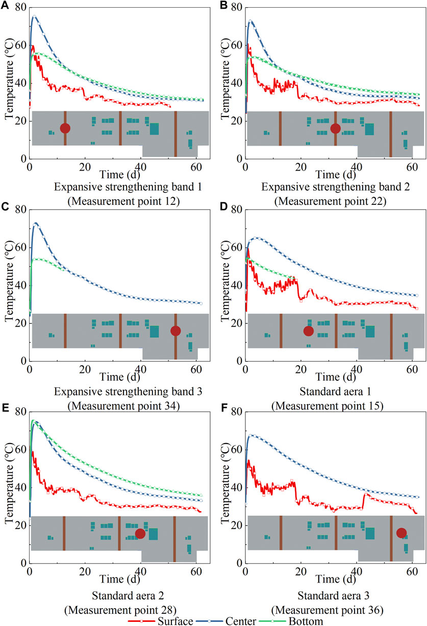
Figure 9. Temperature-time curves of expansion reinforcement band and standard area.
Upon analyzing the 3 measurement points on the expansive strengthening band, it was discerned that the highest temperature all manifested in the central region, transpiring between 36 and 48 h, with the temperature reaching 73–75°C. This observation is congruent with the summary of the temperature development process of the raft in Section 3.1. Notably, the temperature in the central region exhibited a rapid decline subsequently, and by the 12th day, the temperature had descended from 73 to 75°C to 48–50°C. Additionally, it was observed that in the initial 48 h, the temperature curves of the surface and bottom of the concrete displayed a high degree of consistency. However, after the surface temperature reached its zenith, the rate of decline was significantly swifter than that of the bottom, which can be ascribed to the disparate heat dissipation conditions of the surface and bottom discussed earlier.
In the standard region, the temperature-time curves observed at measurement points 15 and 36 exhibit a pattern akin to the expansive strengthening band, but the temperature is lower, with the highest temperature only being 67.8°C, which is 9.7% lower than the highest temperature of the expansive strengthening band. This discrepancy can be attributed to the inferior grade of concrete utilized in the standard region, which engenders less heat of hydration (Wang et al., 2022). However, measurement point 28 presents a unique pattern, where the temperature curves of its bottom and center almost coincide. This anomaly can be attributed to the large quantity of elevator and catchment well pits near measurement point 28. These structures augment the thickness of the raft, leading to an increase in the heat of hydration, thereby elevating the bottom temperature. This will engender a more substantial bottom-surface temperature difference in this region relative to other regions. Hence, when executing temperature surveillance, it is not only essential to ensure that the inner-surface temperature difference does not surpass the prescribed threshold, but it is also crucial to ascertain that the bottom-surface temperature difference remains within the specified limit.
During the temperature development process in the expansive strengthening band and the standard region, the maximum inner-surface temperature difference is significant. The surface temperature reaches its zenith after about 48 h, and then commences to decline, while the center temperature is still ascending. When the center temperature reaches its zenith, the temperature difference between the center and the surface also reaches its maximum. For instance, the internal surface temperature difference of measurement point 22 reaches its maximum value of 24.5°C at 72 h. This observation elucidates the temporal evolution of the inner-surface temperature difference, and establishes that the apex of this differential is reached during the thermal transfer and release phase. Consequently, during temperature surveillance, it is imperative to rigorously monitor the inner-surface temperature difference during the thermal transfer and release phase, particularly when the surface temperature attains its zenith and commences to decline. If the inner-surface temperature difference approaches or even meets the standard threshold, it becomes necessary to implement insulation and maintenance procedures on the raft surface to mitigate the inner-surface temperature difference.
3.3.2 Corner point of the raft
To scrutinize the temperature and strain temporal characteristics of the raft’s corner points, specific measurement points were selected for in-depth analysis, encompassing measurement points 5, 19, 31, 32, 41, and 40. Measurement points 5, 32, 41, and 40 are situated at the positive corners of the raft, measurement point 19 is positioned at the edge of the raft, and measurement point 31 is located at the negative corner of the raft. The temperature-time curve of the corner points is illustrated in Figure 10.
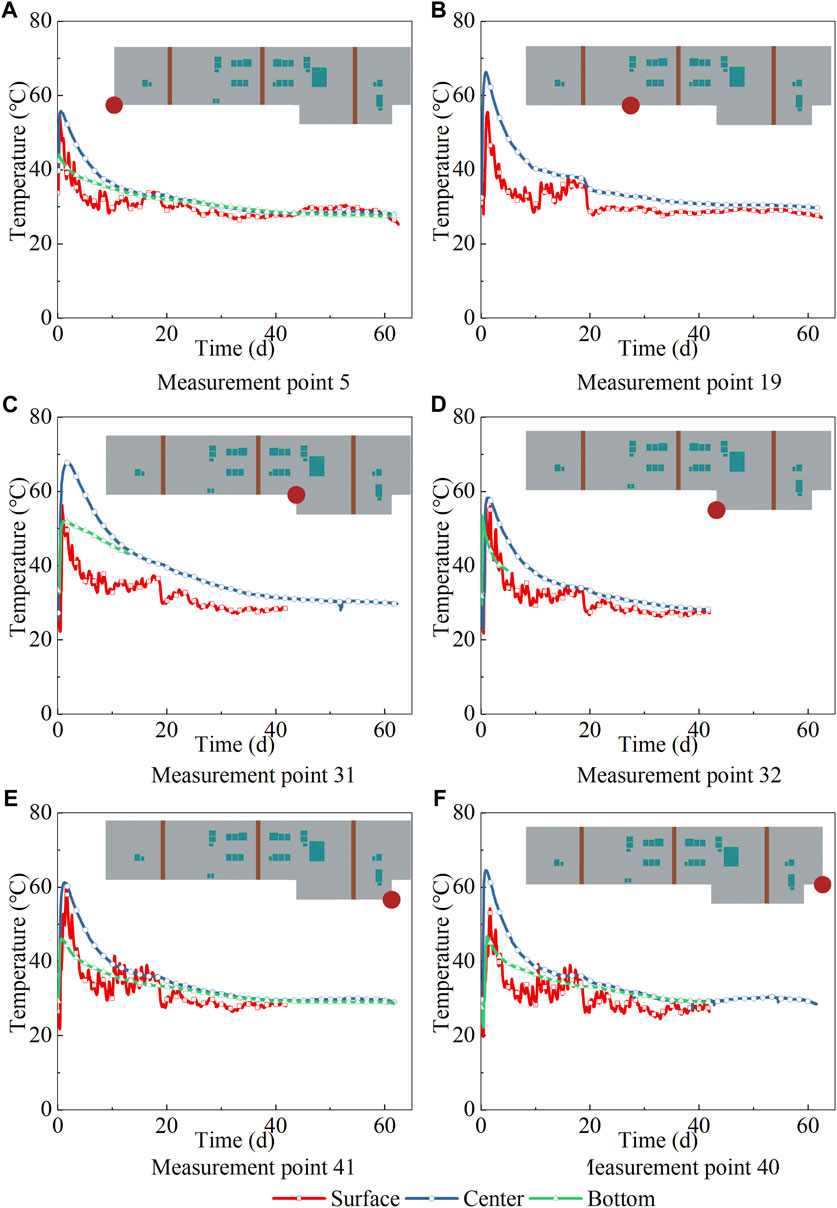
Figure 10. Temperature-time curves of corner point.
There exists a significant disparity between the temperature-time characteristics of the positive and negative corners. The positive corners exhibit a superior heat dissipation efficiency, the central temperature descends rapidly, and the inner-surface temperature difference of the measurement points is minimal, with a maximum of merely 17°C. In contrast, the negative corners display an inferior heat dissipation efficiency, the central temperature descends slowly, and the internal surface temperature difference is substantial, reaching a maximum of 24.8°C. These findings suggest that when conducting temperature monitoring, special attention should be accorded to monitoring the temperature evolution at the negative corners to prevent the internal surface temperature difference from exceeding an acceptable limit.
3.4 Strain-time characteristic
3.4.1 Expansive strengthening band and standard region
To delve deeper into the strain-time attributes of the raft, specific measurement points situated on 3 expansive strengthening bands (namely measurement points 12, 22, 34) and measurement points in 3 standard regions (specifically, measurement points 15, 28, 36) were selected for additional analysis, as depicted in Figure 11. Corresponding to the temperature-time characteristics, compressive strain would be engendered during the heating process. The highest temperature and the maximum compressive strain both transpired in the central region, which was attributable to the thermal expansion being constrained by factors such as the foundation and reinforcement, thereby generating compressive strain. The maximum compressive strain in the center of the expansive strengthening band could reach −425∼−350 με, while the maximum compressive strain in the center of the standard region could only reach −300∼−220 με. One aspect of the reason is that the temperature of the expansive strengthening band is higher and the thermal expansion is larger, and another aspect of the reason is that the concrete of the expansive strengthening band has an expansion effect. In addition, due to this expansion effect, the strain growth of the concrete in the expansive strengthening band is less during the temperature reduction stage, that is, the shrinkage effect is not very pronounced. The strain of the concrete in the expansive strengthening band increased from −425∼−350 με to −191∼−144 με, and the concrete in the expansive strengthening band was consistently in a state of compression. Concurrently, the strain of the concrete in the standard region increased from −300∼−220 με to −101–14 με, and tensile strain appeared in the concrete in the standard region.
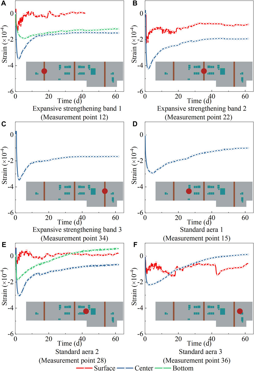
Figure 11. Strain-time curves of expansion reinforcement band and standard area.
For measurement point 28, during the thermal accumulation phase, the temperature rise at the bottom was akin to that at the center. However, the constraint conditions at the bottom were not as robust as those at the center, resulting in a compressive strain at the bottom that only reached −182 με, which is 40.5% less than the maximum compressive strain of −306 με at the center. When the temperature descended, the strain at the bottom escalated, reaching a maximum of 61 με. Commencing from the 30th day, the bottom strain surpassed the surface strain, a unique phenomenon observed across all measurement points. This can be attributed to the fact that from the 1st to the 30th day, the surface temperature descended from 56.8°C to 31°C, a cumulative decrease of 25.8°C, while the bottom temperature descended from 75.3°C to 46.3°C, a cumulative decrease of 29°C, thereby exhibiting a larger temporal gradient of the bottom temperature.
The maximum strain range of the expansive strengthening band is −74–19 με, all appearing on the surface, while the maximum strain range in the standard region is 13–61 με. Within 60 days post the completion of the concrete pouring, the tensile strain of the concrete in the expansive strengthening band and the standard region did not exceed the standard limit of 95 με stipulated in the “Code for design of concrete structures” (Ministry of Housing and Urban-Rural Development of the People’s Republic of China, 2010). Furthermore, the raft exhibited no signs of cracking during empirical testing conducted on-site. This indicates that the method proposed in this paper to achieve seamless construction of a hundred-meter scale super-length raft using a expansive strengthening band is feasible and has value for further promotion.
3.4.2 Corner point of the raft
The strain-time trajectory of the raft corner points is depicted in Figure 12. During the cooling phase, certain distinct strain patterns were discerned. The positive corner, which experiences less constraint during the shrinkage process, exhibits a reduced tensile strain, with the peak tensile strain being 65 με, which is within the standard threshold of 95 με stipulated in the “Code for design of concrete structures” (Ministry of Housing and Urban-Rural Development of the People’s Republic of China, 2010). Conversely, due to the potential stress concentration at the negative corner (Pilkey, 1999), the negative corner is subject to greater constraint. As the negative corner undergoes shrinkage, it exhibits an increased tensile strain, with the peak tensile strain reaching 123 με, surpassing the standard threshold of 95 με. This implies that particular attention should be devoted to the potential issue of concrete cracking at the negative corner of the raft.
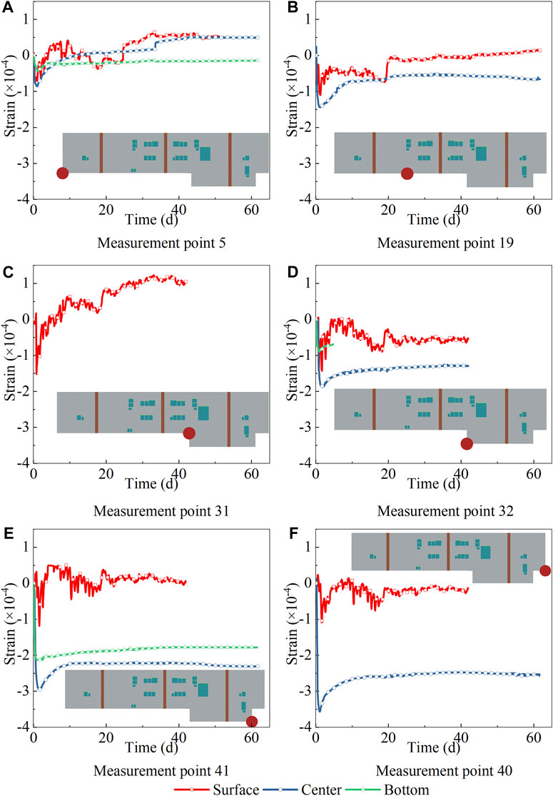
Figure 12. Strain-time curves of corner point.
3.5 A novel temperature control index: bottom-surface temperature difference
Currently, the temperature gradient index delineated in the regulations predominantly pertains to the inner-surface temperature difference (Ministry of Housing and Urban Rural Development of the People’s Republic of China, 2018). The fundamental tenet of this thermal control index is that when the inner-surface temperature difference surpasses the standardized threshold, i.e., when the surface temperature is excessively low and the center temperature is high, the surface concrete undergoes cooling and shrinkage due to the fundamental principle of thermal expansion and contraction. However, this shrinkage is constrained by the central concrete, leading to tensile stress on the surface. This temperature control index, however, overlooks a significant influencing factor, which is the bottom temperature. The deformation coordination of raft concrete due to thermal disparity is a holistic effect, rather than merely involving the surface and center of the concrete. Although the bottom temperature is relatively low compared to the center temperature, it will also undergo cooling shrinkage. However, on one hand, due to the lowest surface temperature, and on the other hand, due to the overall deformation coordination of the raft, the overall deformation of the raft remains surface shrinkage, but is constrained by the center and bottom. Therefore, the bottom-surface temperature difference is also a significant temperature control index. To substantiate this theory, this manuscript scrutinizes the correlation between the surface strain of raft concrete and the bottom-surface temperature difference and inner-surface temperature difference, as depicted in Figure 13 and Figure 14.
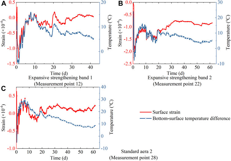
Figure 13. The correlation between surface strain and bottom-surface temperature difference.
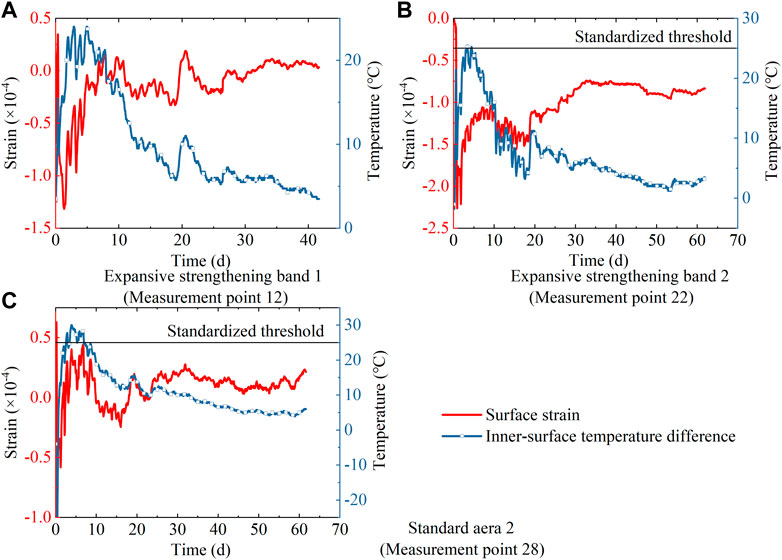
Figure 14. The correlation between surface strain and inner-surface temperature difference.
From Figure 13, it is evident that in the initial 20 days post-pouring, the evolution of surface strain mirrors the evolution of the bottom-surface temperature difference. Post the 20-day mark, the surface strain is primarily influenced by drying shrinkage, and the impact of cooling shrinkage progressively diminishes. From Figure 14, it is observable that the evolution of surface strain does not align perfectly with the evolution of the inner-surface temperature difference. For instance, for expansive strengthening band 1, from the 5th to the 8th day, the inner-surface temperature difference descends from 24°C to 21°C, but the surface strain paradoxically escalates from −5 με to 17 με. Furthermore, the inner-surface temperature difference of the expansive strengthening band 2 and the standard region 2 surpassed the standardized threshold during certain time periods, but the surface strain during this period was still less than the ultimate tensile strain of the concrete. Based on the conclusions and analysis of these monitoring data, this manuscript advocates the use of the bottom-surface temperature difference as a novel temperature control index, and based on the monitoring data of this on-site test, the threshold is determined to be 30°C.
4 Conclusion
This manuscript presents a methodology for the seamless construction of a hundred-meter scale super-length raft structure. This approach was empirically tested on a raft that spans 130 m in length and 1.9 m in thickness in a construction project executed by the China Construction Third Engineering Bureau Group Co., Ltd. A temperature-strain monitoring system was employed to track the temperature and strain of the raft, furnishing experimental data to validate the feasibility and safety of this construction methodology. The pivotal conclusions derived from this research are enumerated as follows:
(1) Commencing from the inception of the raft pouring to 60 days subsequent to the pouring, the peak tensile strain of the raft was 65 με, barring a few corner points. Furthermore, the raft exhibited no signs of cracking during empirical testing conducted on-site. This signifies that the seamless construction methodology proposed in this manuscript for hundred-meter scale super-length raft structures is both feasible and safe, and possesses substantial potential for promotion in this domain.
(2) Upon evaluating the correlation between strain dispersion and strain-temperature differential in the raft’s thickness dimension, Relative to the inner-surface temperature difference, the surface strain exhibits a more potent association with the bottom-surface temperature difference. Therefore, a novel temperature control index (the bottom-surface temperature difference) was introduced. In light of the empirical test outcomes obtained on-site, the threshold for the temperature control index is established at 30°C.
(3) In the process of architecting a temperature-strain monitoring system, it is imperative to enhance the density of sensors within the surface of lowering plate region, the center of the raft terminal point, and the bottom of the elevator and catchment well pits. Owing to the substantial spatial gradient of temperature present in these regions, these augmentations are crucial to promptly detect alterations in the inner-surface temperature difference and bottom-surface temperature difference.
(4) The apex of the inner-surface temperature difference is reached during the thermal transfer and release phase. During temperature surveillance, it is imperative to rigorously monitor the inner-surface temperature difference during this phase, particularly when the surface temperature attains its zenith and commences to decline. If the inner-surface temperature difference approaches or even meets the standard threshold, it becomes necessary to implement insulation and maintenance procedures on the raft surface to mitigate the inner-surface temperature difference.
(5) The subsequent phase in the research agenda entails the establishment of a finite element model and the execution of parameter analysis predicated on the verification of the model’s reliability. This encompasses the analysis of the functional correlation between the spacing, breadth, and concrete expansion rate of the expansive strengthening bands with the length and thickness of the raft. The objective is to broaden the application parameters of the seamless construction methodology for super-length raft structures, thereby facilitating its application to more extensive and thicker raft structures.
Data availability statement
The original contributions presented in the study are included in the article/Supplementary Material, further inquiries can be directed to the corresponding author.
Author contributions
BH: Conceptualization, Data curation, Investigation, Software, Visualization, Writing–original draft, Writing–review and editing. HW: Funding acquisition, Resources, Supervision, Writing–review and editing. HL: Conceptualization, Project administration, Supervision, Writing–original draft. CD: Funding acquisition, Supervision, Writing–review and editing. YZ: Funding acquisition, Investigation, Supervision, Writing–review and editing. WX: Data curation, Methodology, Writing–review and editing. GZ: Conceptualization, Writing–review and editing. CS: Software, Writing–review and editing.
Funding
The author(s) declare that financial support was received for the research, authorship, and/or publication of this article. This research was funded by Chongqing Construction Science and Technology Plan Project, grant number Chengke Zi 2023 No. 8–6.
Acknowledgments
The authors express their gratitude to the reviewers for their valuable feedback and suggestions aimed at enhancing the paper’s quality.
Conflict of interest
Authors BH, HW, HL, CD, YZ, WX, GZ, and CS were employed by the China Construction Third Engineering Bureau Group Co., Ltd.
Publisher’s note
All claims expressed in this article are solely those of the authors and do not necessarily represent those of their affiliated organizations, or those of the publisher, the editors and the reviewers. Any product that may be evaluated in this article, or claim that may be made by its manufacturer, is not guaranteed or endorsed by the publisher.
Supplementary material
The Supplementary Material for this article can be found online at: https://www.frontiersin.org/articles/10.3389/fmats.2024.1367600/full#supplementary-material
References
Batog, M., and Giergiczny, Z. (2014). Influence of mass concrete constituents on its properties. Constr. Build. Mater. 146, 221–230. doi:10.1016/j.conbuildmat.2017.04.085
Ha, J.-H., Jung, Y. S., and Cho, Y.-G. (2014). Thermal crack control in mass concrete structure using an automated curing system. Autom. Constr. 45, 16–24. doi:10.1016/j.autcon.2014.04.014
Jin, J. (2002). Design suggestion about crack precaution and reduction caused by temperature and shrinkage jointly in over-long concrete structure. Ind. Constr. 2002 (06), 57–59. doi:10.13204/j.gyjz2002.06.019
Li, S., Feng, Y., and Yang, J. (2021). Expansion mechanism and properties of magnesium oxide expansive hydraulic cement for engineering applications. Adv. Mater. Sci. Eng. 2021, 1–9. doi:10.1155/2021/5542072
Liu, J., Liu, Y., Zhang, N., Ma, Z., and Bai, Y. (2020). Research on temperature action and cracking risk of steel–concrete composite girder during the hydration process. Arch. Civ. Mech. Eng. 47, 47. doi:10.1007/s43452-020-00050-0
Liu, Y., Zhang, J., Chang, J., and Zhao, Y. (2022). Use of cement hydration heat as heating resource in curing of precast concrete - temperature rise simulation. J. Adv. Concr. Technol. 20, 564–580. doi:10.3151/jact.20.564
Ming, X., Huang, J. C., and Li, Z. (2022). Materials-oriented integrated design and construction of structures in civil engineering—a review. Front. Struct. Civ. Eng. 16, 24–44. doi:10.1007/s11709-021-0794-9
Ministry of Housing and Urban-Rural Development of the People’s Republic of China (2010). GB 50010-2010 Code for design of concrete structures. Beijing: China Architecture and Building Press.
Ministry of Housing and Urban-Rural Development of the People’s Republic of China (2018). Standard for construction of mass concrete. Beijing: China Architecture and Building Press.
Ministry of Housing and Urban-Rural Development of the People’s Republic of China (2023). Standard for seamless construction for super-length concrete structure. Beijing: China Construction Publishing Media Co, Ltd.
Myint, S. H., Tanapornraweekit, G., and Tangtermsirikul, S. (2021). Investigation of expansive concrete structures through strain monitoring in field structures. Asian J. Civ. Eng. 22, 565–578. doi:10.1007/s42107-020-00332-1
Ouyang, J., Chen, X., Huangfu, Z., Lu, C., Huang, D., and Li, Y. (2019). Application of distributed temperature sensing for cracking control of mass concrete. Constr. Build. Mater. 197, 778–791. doi:10.1016/j.conbuildmat.2018.11.221
Qin, W. (2006). Shrinkage and cracking of concrete and its evaluation and prevention. Concrete 04, 19–23.
Sargam, Y., Faytarouni, M., Riding, K., Wang, K., Jahren, C., and Shen, J. (2019). Predicting thermal performance of a mass concrete foundation – a field monitoring case study. Case Stud. Constr. Mater. 11, e00289. doi:10.1016/j.cscm.2019.e00289
Tatro, S. B., Allen, J. C., Arnold, T. E., Bass, R. P., Best, F. J., Bombich, A. A., et al. (2007). Report on thermal and volume change effects on cracking of mass concrete. ACI Comm. 207.
Tian, C. J., Wang, Y. Z., Qiu, K., and Yang, Q. l. (2022). Effects of submicron-MgO and nano-MgO on the expansion and microscopic properties of high-performance concrete. J. Cent. South Univ. 29, 3186–3200. doi:10.1007/s11771-022-5090-x
Truman, K. Z., Petruska, D. J., and Norman, C. D. (1991). Creep, shrinkage, and thermal effects on mass concrete structure. J. Eng. Mech. 117 (6), 1274–1288. doi:10.1061/(ASCE)0733-9399(1991)117:6(1274)
Wang, Y., Tian, Q., Li, H., and Wang, Y. (2022). Humidity sensitivity of hydration of expansive agent and its expansive efficiency in ultra-high performance concrete. Crystals 12 (2), 195. doi:10.3390/cryst12020195
Xie, Y., Du, W., Xu, Y., Peng, B., and Qian, C. (2023). Temperature field evolution of mass concrete: from hydration dynamics, finite element models to real concrete structure. J. Build. Eng. 65, 105699. doi:10.1016/j.jobe.2022.105699
Xin, J., Liu, Y., Zhang, G., Wang, Z., Yang, N., Qiao, Y., et al. (2021). Comparison of thermal cracking potential evaluation criteria for mass concrete structures. Mater. Struct. 54, 243. doi:10.1617/s11527-021-01840-5
Yang, Z., Yang, Y., Ji, X., Xu, K., and Wang, H. (2022). Experimental and numerical simulation study on hydration heat of expansive mass concrete. Mater. Res. Appl. 16 (2), 222–227.
Keywords: super-length raft structure, seamless construction, expansive strengthening band, on-site test, temperature-strain monitoring system
Citation: Han B, Wang H, Liao H, Dai C, Zhao Y, Xu W, Zhou G and Shi C (2024) Investigation into the seamless construction for hundred-meter scale super-length raft structure based on magnesia expansive agent concrete. Front. Mater. 11:1367600. doi: 10.3389/fmats.2024.1367600
Received: 09 January 2024; Accepted: 18 March 2024;
Published: 04 April 2024.
Edited by:
Jialuo He, Washington State University, United StatesReviewed by:
Hui Li, Hebei University of Technology, ChinaChongsheng Cheng, Chongqing Jiaotong University, China
Copyright © 2024 Han, Wang, Liao, Dai, Zhao, Xu, Zhou and Shi. This is an open-access article distributed under the terms of the Creative Commons Attribution License (CC BY). The use, distribution or reproduction in other forums is permitted, provided the original author(s) and the copyright owner(s) are credited and that the original publication in this journal is cited, in accordance with accepted academic practice. No use, distribution or reproduction is permitted which does not comply with these terms.
*Correspondence: Hong Liao, liaohong2024@126.com