Bending performance of prefabricated ultra-thin UHPC unit plate reinforced orthotropic steel bridge decks
 Xiang Zhou
 Jinlong Jiang
 Le Liu1,2
  Zhongya Zhang
- 1State Key Laboratory of Mountain Bridge and Tunnel Engineering, Chongqing Jiaotong University, Chongqing, China
- 2School of Civil Engineering, Chongqing Jiaotong University, Chongqing, China
To address the challenges related to lengthy construction period, complex maintenance requirement, and the elevated risk of shrinkage cracking associated with cast-in-place UHPC reinforcement of orthotropic steel bridge decks. This paper proposes a novel solution that prefabricated ultra-high-performance concrete (UHPC) slab with epoxy bond connection is used as a reinforcement layer for orthotropic steel bridge decks. Four sets of bending tests on composite bridge deck were carried out to compare the flexural performance of composite bridge decks under different joint forms and loading patterns. The results indicate that the precast UHPC decks delaminated from the epoxy bonding layer without failure of the epoxy layer itself in all cases. The positive bending capacity of the jointless composite bridge deck is approximately 27.67 kN, while the negative bending capacity is around 16.58 kN. For the composite bridge deckwith epoxy adhesive joints (EA-J-Ln), the negative bending capacity is 2.54 kN, and the negative bending capacity of the joint area reinforced with carbon fiber cloth (EA-JC-Ln) is increased to 4.17 kN. Therefore, the use of carbon fiber cloth can significantly improve the bending resistance of the joints. Finally, numerical model of the composite deck based on Cohesive Zone Model (CZM) was established, validating the applicability of this simulation method in the novel composite bridge deck.
1 Introduction
Ultra-high-performance concrete (UHPC) is an advanced construction material known as its high strength, high ductility and excellent durability (Du et al., 2021; 2022; Jia et al., 2023). It is widely used in fields such as bridge structures, house construction, maintenance and reinforcement, etc (Shao et al., 2018; Wang et al., 2021; Zhang Z. et al., 2023; Zou et al., 2023b). It is worth noting that concrete shrinkage can significantly impact the long-term performance of NC structures (Hung et al., 2021; Men et al., 2023). However, this influence can be mitigated in UHPC components treated with steam curing (Yoo et al., 2014a; 2014b), enabling the rapid achievement of desired high strength within approximately 72 days. Therefore, UHPC is an exceptional material for prefabricated structural components, which can saved time costs (Zhang et al., 2022; Benedetty et al., 2023) and provide higher strength, superior durability, and lower life-cycle costs (Wang et al., 2021; Fang et al., 2022; Jia et al., 2023).
Shear studs, one of the commonly used connecting components between orthotropic steel bridge deck and UHPC (Jiang et al., 2022), are widely used in composite structures due to their convenient installation (Fang et al., 2022), simple load transferring pathway (Hu et al., 2023), and cost-effectiveness, among other characteristics (Shi et al., 2022; Bu et al., 2023). However, the extensive use of shear studs inevitably introduces welding defects and residual stresses (Khorramian et al., 2017; Ding et al., 2023; Liu et al., 2023), which may pose inconvenience during the later disassembly or replacement of the structure (Li Y. et al., 2023). Furthermore, the availably shortest height of shear studs in the market is currently 35 mm (Shao et al., 2018), thereby limiting the development of ultra-thin UHPC panels (Bu et al., 2023; Leng et al., 2024).
In the field of Prefabricated Concrete Segmental Bridges (PCSB), the concept, development, and global acceptance of segmental structures represent one of the most remarkable achievements in civil engineering (Jiang et al., 2015). The use of prefabricated UHPC segmental bridge decks can significantly shorten construction time and improve the efficiency of bridge structure construction (Yu et al., 2022). However, the inevitable issue of joints between prefabricated UHPC bridge decks poses a challenge. Figure 1 illustrates the novel assembly of prefabricated UHPC bridge decks were proposed in this study for reinforcing orthotropic steel bridge decks. By adopting this system, the limitations posed by shear stud connections on bridge structures can be effectively overcome, and the construction of bridge decks using prefabricated components can be realized. This approach not only reduces construction time and economic costs but also facilitates the reinforcement of orthotropic steel bridge decks. Additionally, the connection between prefabricated UHPC decks and steel bridge decks can be achieved using an epoxy bonding layer (Zou et al., 2021a). The joints of prefabricated UHPC bridge decks are divided into wet joints and epoxy joints. Ahmed and Aziz (2019) demonstrated through direct shear tests that the shear resistance of epoxy resin joints is 25%–28% higher than that of wet joints, with a more uniform distribution of shear stress. Pan et al. (2023) studied the shear performance of epoxy-bonded joints with large teeth, considering parameters such as shear teeth. The study showed that the large teeth has a significant impact on the shear performance of joints, and proposed relevant specifications for the teeth size. Connecting prefabricated UHPC decks with steel plates using epoxy bonding (Sun et al., 2021; Li et al., 2022a) can reduce damage to the steel bridge deck and satisfy load-bearing capacity and construction convenience (Pang et al., 2022; Zhang P. et al., 2023). Additionally, as a rigid connection layer, bond can significantly reduce interfacial slippage and improve the overall performance of composite structures (Luo et al., 2012; Fang et al., 2024). Li C. et al. (2023) conducted experiments and found that the shear performance using epoxy bonding interface is related to the bonding area, and summarized various factors affecting shear bond strength, such as the strength of epoxy bonding agents, roughness of bonding surfaces, concrete strength, and temperature. Further research on steel-UHPC components under bending was conducted by Wang et al. (2019) and Duan et al. (2020), who studied the interfacial bonding performance under combined bending and bending-shear actions based on three-point bending and four-point bending tests. The extensive researches on epoxy bonding interfaces in steel-UHPC composite bridge decks evident that epoxy bonding interfaces can provide high load-bearing capacity to meet the requirements of practical engineering applications.
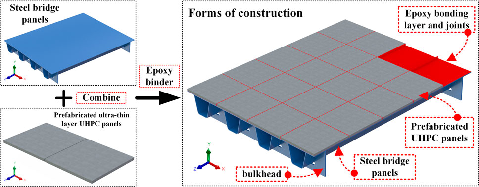
Figure 1. OSD-UHPC epoxy bonding layer connection solution.
To investigate the flexural performance of the novel assembly-type epoxy-bonded prefabricated UHPC bridge deck (Figure 1) proposed in this study, four sets of bending performance tests on composite bridge deck were conducted. Joints in the negative bending moment zone often experience tension, and the bonding performance of the interface at the joints needs to be verified. Therefore, the bending performance of epoxy-bonded joints in prefabricated UHPC panels under different joint forms, positive bending moment loading, and negative bending moment loading were discussed. Experimental failure modes, load-deflection curves, load-interface slip curves, and strain distribution were evaluated to determine appropriate epoxy bonding joint forms for prefabricated UHPC panels. Furthermore, a numerical simulation method based on Cohesive Zone Model (CZM) is proposed for analyzing this bonding joint.
2 Materials and methods
2.1 Specimen design
To investigate the bending performance of steel- UHPC composite bridge decks with epoxy bonded joints, four sets of bending tests were designed. The overall specimen design is illustrated in Figure 2, consisting of a steel plate, epoxy adhesive, carbon fiber cloth, and precast UHPC slab. The overall dimensions are 800 mm in length, 150 mm in width, and 42 mm in height. The steel plate dimensions are 800 mm in length, 150 mm in width, and 10 mm in thickness. The precast UHPC slab dimensions are 800 mm in length, 150 mm in width, and 30 mm in thickness. The epoxy bonded layer dimensions are 800 mm in length, 150 mm in width, and 2 mm in thickness, and the carbon fiber cloth dimensions are 150 mm in length, 20 mm in width, and 2 mm in thickness. To simulate the actual joints between precast UHPC slabs in bridge structures, two sets of specimens with 2 mm thick epoxy bonded joints were designed, and one set was reinforced with a 20 mm width carbon fiber cloth in the joint area. The specimens without joints were subjected to both positive and negative bending moments, while the specimens with joints were subjected to negative bending moments. All precast UHPC slabs had smooth surfaces, and epoxy bonded joints were used to naturally bond the precast UHPC slabs to the steel plates. Specific specimen parameters are detailed in Table 1.
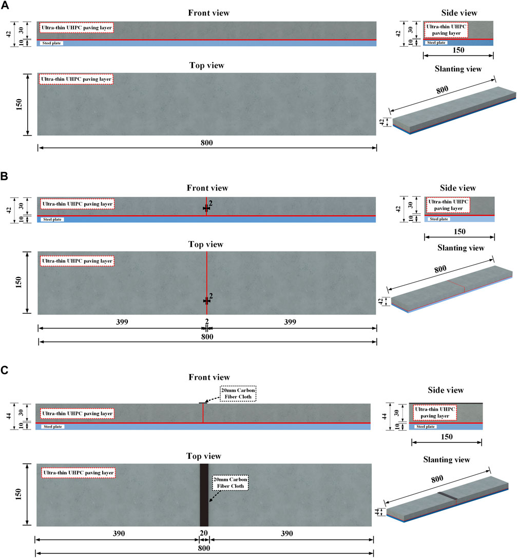
Figure 2. Test specimen construction details (units: mm). (A) Specimen of EA; (B) Specimen of EA-J; (C) Specimen of EA-JC.
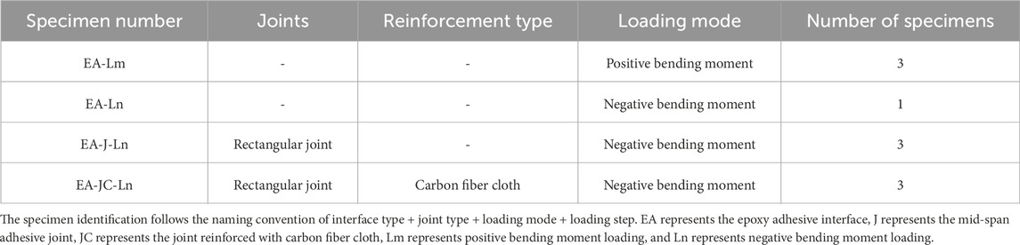
Table 1. Test specimen parameters.
2.2 Material properties
2.2.1 UHPC and steel
The mixture proportions for the UHPC raw materials used in the experiments are provided in Table 2. The UHPC mix includes a volume fraction of 3% of straight steel fibers (yield strength greater than 1,200 MPa) with a diameter of 0.12 mm and a length of 8 mm. The manufacturing process of UHPC is as follows: first, the dry materials are mixed according to the proportions in Table 3, and then they are dry mixed in a mixer for 2 min to ensure even mixing of the dry ingredients. After that, water and a water-reducing agent are added evenly and mixed for 1 min. Once the dry materials are thoroughly mixed with water and the water-reducing agent, steel fibers are evenly sprinkled and mixing continues for 6 min to complete the preparation of UHPC. Additionally, the strength grade of steel used for the specimens was Q345.
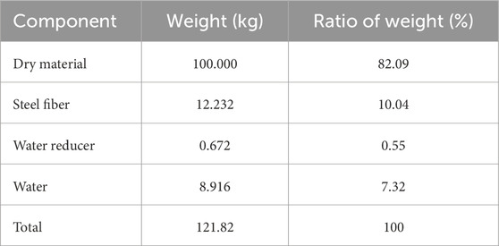
Table 2. Specific mix proportion of UHPC.
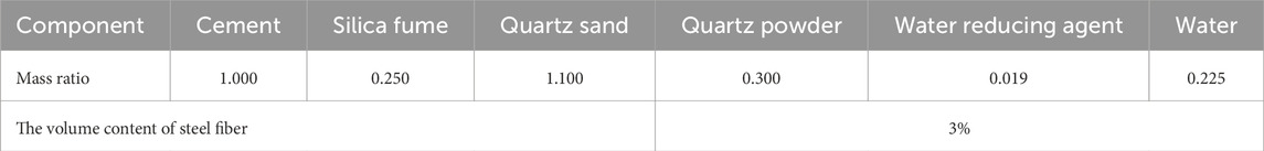
Table 3. Dry material mix ratio of UHPC.
UHPC and steel were tested according to the standards “High-Performance Concrete” (GB/T31387-2015) (GB/T31387-2015 (General Administration of Quality Supervision, 2015)) and “Metallic Materials - Tensile Testing - Part 1: Method of Test at Room Temperature” (GB/T 228.1-2010) (GB/T 228.1-2010 (General Administration of Quality Supervision, 2010)), respectively. The schematic representation of the tests and the material properties are shown in Figure 3 and Table 4, respectively. In the table, fy, fu, and Es represent the yield strength, ultimate strength, and elastic modulus of Q345 steel. fc, ft, and Ec represent the compressive strength, tensile strength, and elastic modulus of UHPC.
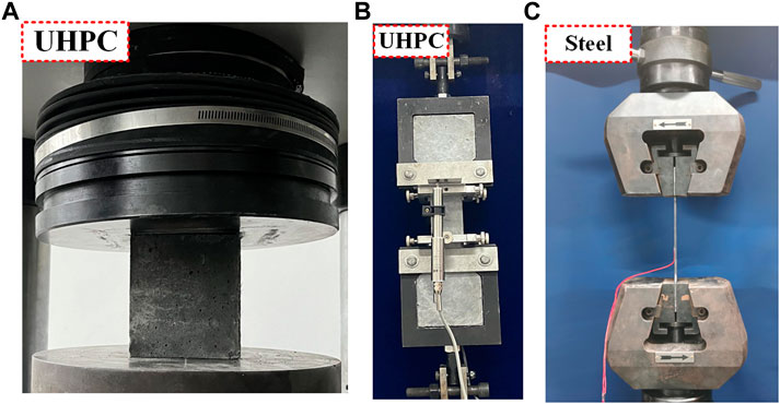
Figure 3. Steel and UHPC material properties tests. (A) UHPC compressive test; (B) UHPC tensile test; (C) Steel tensile test.
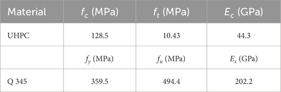
Table 4. Material properties of steel and UHPC.
2.2.2 Epoxy binder and carbon fiber cloth
The epoxy adhesive used is CBSR-A/B Steel Filling Adhesive produced by Cabon Technology Group Co., Ltd. The primary components are the base agent CBSR-A and the hardener CBSR-B, with a material weight mixing ratio of 2:1. According to the “Test Methods for Properties of Resin Castings” (GB/T 2567-2021) (Test methods for properties of resin casting body: GB/T 2567-2021) ([in Chinese]), tensile and compression tests on the epoxy adhesive are conducted using an electronic universal testing machine. The mechanical properties are detailed in Table 5.

Table 5. Epoxy adhesive and carbon fiber cloth material properties.
The carbon fiber fabric used in this study was acquired from Shanghai Yuezi Industrial Co., Ltd. (Shanghai, China). The fabric is woven from 12K carbon fiber filaments, with a carbon content of more than 98%, a thickness of 0.167 mm, and a density of 300 g/cm³. According to the “Code for acceptance of construction quality of strengthening building structures, 2010” (GB 50550-2010 ([in Chinese]), tensile tests on the carbon fiber fabric were conducted using an electronic universal testing machine. The mechanical properties are detailed in Table 5.
2.3 Specimen preparation
The precast UHPC slabs were naturally bonded to the steel plates using an epoxy bonded layer. The specific procedure was as follows: a) Fabrication of molds and casting of precast UHPC slabs; b) After casting, the UHPC required 48 h of curing at room temperature, followed by demolding and 72 h of steam curing at 95°C; c) Cleaning the surface of the steel plates with acetone to remove all debris and rust; d) Fixing the precast UHPC slabs onto the steel plates with a 2 mm gap maintained between them; e) Preparation of epoxy adhesive; f) Injecting the epoxy adhesive into the 2 mm gap through pre-drilled holes until a small amount of adhesive overflowed from the edges; g) Curing the specimens at room temperature for 7 days until the epoxy bonded layer reached its full strength. The preparation process of the specimens is illustrated in Figure 4.
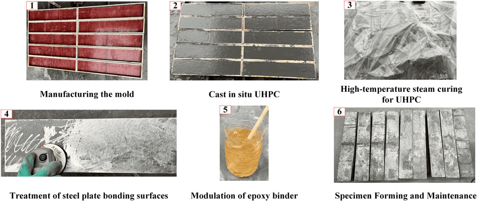
Figure 4. Test specimen fabrication process.
2.4 Loading scheme and measurement method
Figure 5A illustrates the loading method and measurement point arrangement for the specimens. All composite bridge decks are subjected to a four-point loading scheme, enabling a pure bending region of 300 mm at the midspan using a distributing beam. The load is applied using an electronic universal testing machine (MTS Exceed E45.205) at a loading rate of 0.01 mm/s. Displacement sensors D-4 and D-5 are placed 50 mm from the edge of the composite plate to measure deflections at the supports, while displacement sensor D-1 was positioned at the midspan of the specimen to measure midspan deflection. Displacement sensors S-1 to S-2 are arranged on the edge of the side of the specimen to measure the slip at the interface between the UHPC layer and the steel plate. Strain gauges are installed at the top, bottom, and sides of the midspan region to measure strains in the UHPC layer and the steel plate within the pure bending zone.
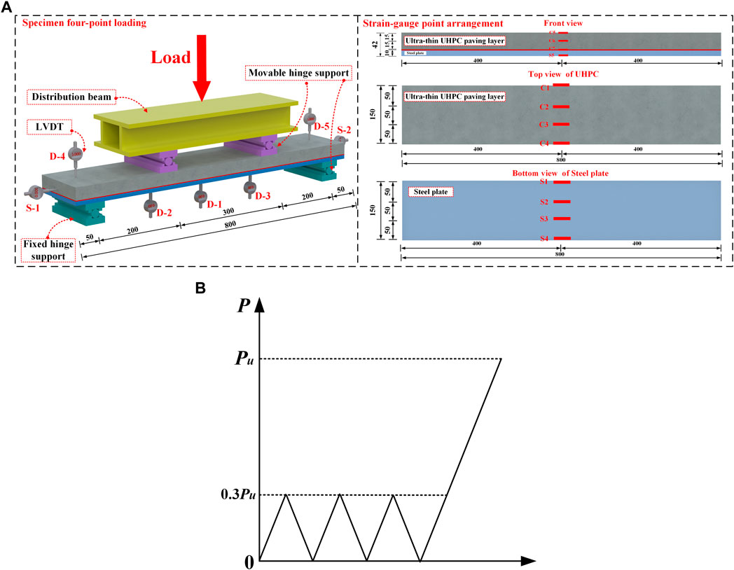
Figure 5. Test loading scheme and measurement point arrangement. (A) Specimen loading device and measurement point arrangement; (B) Monotonic loading process.
For specimens subjected to positive bending moment loading, the UHPC is positioned on top with the steel plate underneath. Conversely, for specimens subjected to negative bending moment loading, the arrangement is reversed. The bending tests of the steel-UHPC composite bridge decks follow the loading scheme used by Zou et al. (2021b). As shown in Figure 5B, preloading with an amplitude of 30% of the ultimate load (Pu) was applied three times to check the potential effects during the loading process. Subsequently, continuous loading is applied until specimen failure, with the observation and recording of crack propagation during the loading process.
3 Results
3.1 Failure mode
The failure characteristics of the specimens under positive bending moment without joints (EA-Lm) are as follows: as the load increases, cracks begin to appear in the pure bending region at mid-span. When the ultimate load Pu is reached, the UHPC slab delaminates from the epoxy bonding layer, accompanied by a “bang” sound. The top of UHPC slab in the pure bending section of the specimen collapses under pressure. The failure mode of this type of specimen indicates excellent bonding performance between the epoxy bonding layer and the steel plate, while the bonding strength between the smooth UHPC slab and the epoxy bonding layer is significantly insufficient, resulting in separation of the steel plate from one side of the UHPC slab. The failure mode of the EA-Lm specimen is shown in Figure 6A.
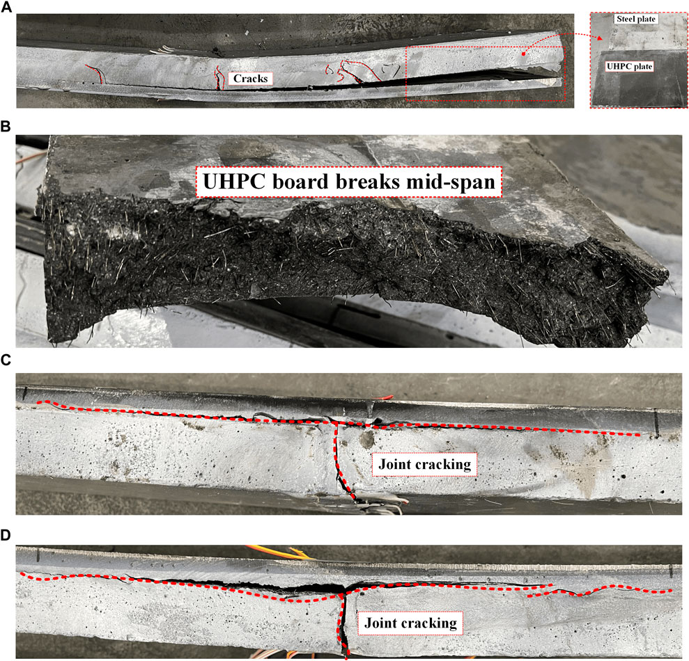
Figure 6. Specimen damage model. (A) EA-Lm; (B) EA-Ln; (C) EA-J-Ln; (D) EA-JC-Ln.
The failure mode of the specimens under negative bending moment without joints (EA-Ln) is shown in Figure 6B. This type of specimen exhibits UHPC rupture and exposed steel fibers on the basis of the failure mode of the EA-Lm specimen. After reaching the peak load Pu, cracks extend upward along the main crack at mid-span, ultimately resulting in rupture of the UHPC slab along the mid-span. At the same time, the bonding strength between the UHPC slab and the epoxy bonding layer is completely lost, leading to separation between the steel plate and the UHPC slab.
The failure modes of the specimens under negative bending moment with joints (EA-J-Ln) and the specimens with joints reinforced with carbon fiber cloth under negative bending moment (EA-JC-Ln) are shown in Figures 6C, D, respectively. The failure characteristics of the two types of specimens are consistent: once the joint cracks, the cracks continue to extend upward, eventually leading to delamination of the prefabricated UHPC slab from the epoxy bonding layer near the joint, while the interface far from the joint remains intact.
3.2 Load-deflection curve
Figure 7A presents the load-deflection curves for the EA-Lm specimen, which can be divided into three stages: a) Elastic stage: Before reaching the ultimate load Pu, the interface of the specimen remains undamaged, and it is in the elastic stage. During this stage, the load continues to increase, and the deflection increases slowly. b) After reaching the ultimate load Pu, there is a sudden failure at the interface, resulting in a sharp drop in load, indicating irreversible damage to the interface. c) Continued loading: The upper load is borne by the steel plate, and the deflection of the specimen continues to increase, but the load increases slowly. Local fragmentation occurs in the UHPC layer near the loading point, resulting in bending failure of the composite bridge deck. The load-deflection curves for these three types of specimens exhibit a similar trend, and their ultimate load Pu is approximately 27.67 kN.
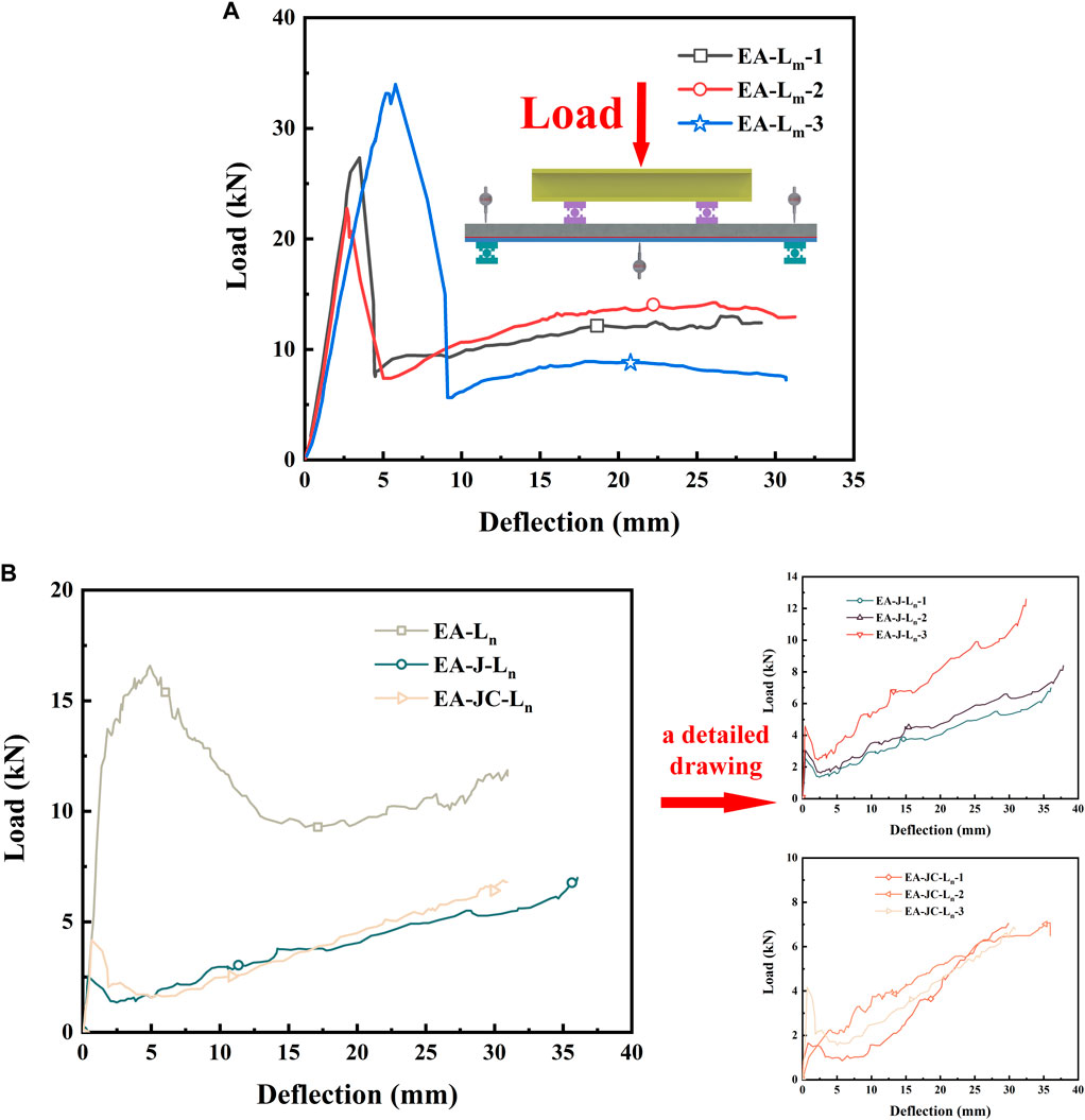
Figure 7. Load-deflection curve. (A) Positive bending moment test. (B) Negative bending moment test.
The load-deflection curves for the negative bending moment tests are shown in Figure 7B, including three types of specimens: EA-Ln, EA-J-Ln, and EA-JC-Ln. It can be observed that the specimen EA-Ln without joint is capable of resisting external loads under negative bending moment loading, with an ultimate load Pu of approximately 16.58 kN. Before reaching the ultimate load Pu, the composite bridge deck is able to jointly bear the external load, and a primary crack appears at the mid-span of the UHPC board and continues to propagate upwards during this process. After reaching the ultimate load Pu, the UHPC board detaches from the epoxy bonding layer in the mid-span bending section. As the load continues to increase, the UHPC board is pulled apart along the primary crack at the mid-span, eventually the composite function was lost, and only the steel plate beared the external load.
The load-deflection curves for EA-J-Ln and EA-JC-Ln specimens exhibit similarities and can be analyzed in three stages: a) Elastic Stage: During this stage, the load continues to increase gradually, and the deflection increases slowly, resulting in a straight upward-sloping curve. The composite bridge deck are jointly stressed and the interface is intact in this stage. b) Ultimate Load Pu Stage: When reaching the ultimate load Pu, cracks propagate upward along the seam near the mid-span. The load experiences a sudden drop, and the deflection increases rapidly, leading to a steep decline in the curve. This phase continues until the UHPC board detaches from the epoxy bonding layer near the seam. c) After Reaching Ultimate Load: In this phase, the UHPC board and epoxy bonding layer at the seam have detached. The composite structure loses its capacity, and all external loads are borne by the steel plate. Comparing the test results of all specimens, it is evident that the failure of EA-J-Ln and EA-JC-Ln specimens occurs at the seam. This indicates that the composite bridge deck has poor resistance under negative bending moment loading, whereas the seam-less specimen EA-Ln can effectively resist external loads in negative bending moment mode. Additionally, the epoxy bonding layer-bonded composite bridge deck exhibits effective resistance to external loads in positive bending moment mode. Therefore, in the design of orthotropic steel bridge decks using prefabricated UHPC deck combined with epoxy bonding layers, it is recommended to place the seam at the location where positive bending moments are generated in the bridge deck. From Figure 7B, it can be observed that the ultimate load of the EA-JC-Ln specimen is approximately twice as high as that of the EA-J-Ln specimen. This indicates that reinforcing the joint area with carbon fiber cloth can enhance its bending performance.
3.3 Load-slip curve
Figure 8 shows the load-slip curves of the specimens. As shown in Figure 8A, the load-slip curve of the EA-Lm specimen indicates that, prior to reaching the ultimate load, the epoxy adhesive layer ensures an effective connection between the UHPC panel and the steel plate, with negligible slip occurring at this stage. Subsequently, upon reaching the ultimate load, the slip at both ends of the specimen escalates and continues to increase. Larger slip occurs on the S-1 side, with a maximum slip value of S-1 = 13.9 mm. Hence, a smooth UHPC panel can achieve effective bonding through the epoxy adhesive layer. The load-slip curves of the EA-Ln, EA-J-Ln, and EA-JC-Ln specimens, as shown in Figures 8B, C, are characterized by the fact that the failure of all three types of specimens occurs at the mid-span joint, and debonding occurs between the UHPC panel and the epoxy layer at the joint, resulting in minimal and almost negligible slip at the ends. The maximum slip value for specimens with only epoxy joints is S-1 = 0.08 mm. For the EA-JC-Ln specimen, which was reinforced at the joint with carbon fiber cloth, the slip at the ends is significantly larger, indicating that the reinforcement of the joint with carbon fiber cloth enhances the bending performance of the epoxy joint, with a maximum slip value of only S-1 = 0.31 mm.
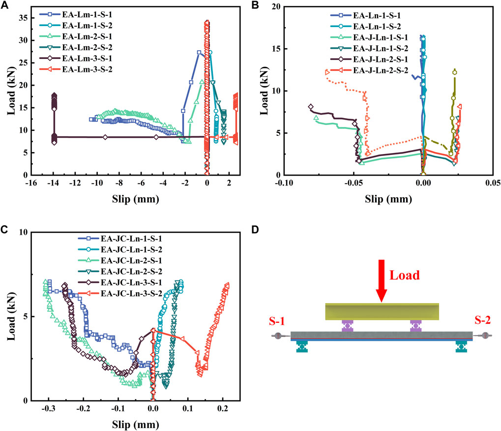
Figure 8. Load-slip curve. (A) EA-Lm interfacial slip curve; (B) EA-J-Ln interfacial slip curve; (C) EA-Ln and EA-JC-Ln interfacial slip curve; (D) Interface slip measurement point location.
3.4 Strain distribution
The strain distribution curves were drawn after averaging the values for specimens in the same group. However, the strain distribution curve for the EA-JC-Ln specimen could not be plotted due to damage to the strain gauges during initial loading. Figure 9A shows the strain distribution curve along the height direction at mid-span for the EA-Lm specimen. Before the applied load reaches the ultimate load Pu = 27.3 kN, the strain at mid-span exhibits a linear distribution. As the load continues to increase, the strain at mid-span shows an increasingly evident nonlinear distribution. However, the strain distribution across the mid-span section always remains linear. The distribution is discontinuous at the steel-UHPC interface, where both the thin UHPC panel and the steel plate exhibit a linear strain distribution. Once the ultimate load Pu = 27.3 kN is reached and the epoxy adhesive layer interface is damaged, the assumption of plane sections being plane no longer holds.
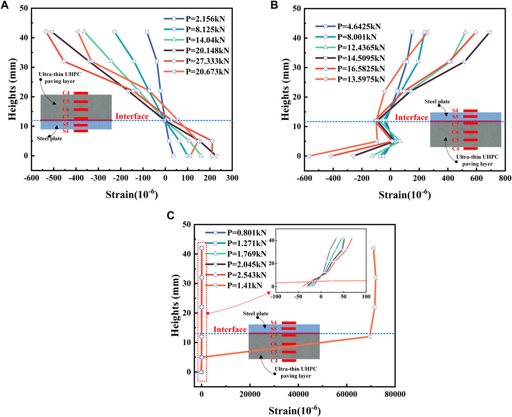
Figure 9. Strain distribution. (A) EA-Lm strain distribution; (B) EA-Ln strain distribution; (C) EA-J-Ln strain distribution.
Figure 9B depicts the strain distribution curve along the height direction at mid-span for the EA-Ln specimen. Throughout the loading process, the strain distribution of the specimen consistently adheres to the plane section assumption, with the neutral axis maintaining a constant position as theoretically expected, as shown in Figure 13B. This is consistent with the low level of interfacial slip for the EA-Ln specimen shown in Figure 8B. In Figure 9C, for the EA-J-Ln specimen, when the load is below 2.5 kN, the strain distribution at mid-span is approximately linear. Before reaching the ultimate load, the epoxy adhesive interface can achieve reliable connection between the thin UHPC panel and the steel plate. After the load exceeds 2.5 kN, sudden extensive damage occurs at the interface around the joint, leading to a sharp increase in strain, which indicats that the joint has fractured and damaged.
4 Numerical simulation
4.1 Finite element models
In this study, a finite element model of the steel-UHPC composite bridge deck was established using the static analysis method in ABAQUS. Based on the symmetry of the steel-UHPC composite bridge deck, a half-model was developed to improve computational efficiency. The symmetrical plane is the x-plane. The steel plate, ultra-thin UHPC, and epoxy adhesive layer were simulated using C3D8R (three-dimensional, 8-node linear solid integrated elements). According to the experimental results, the bonding behavior between the UHPC panel and the epoxy adhesive layer was simulated using cohesive contact properties. The specific finite element model is shown in Figure 10.

Figure 10. Introduction to models.
4.2 Material constitutive model
4.2.1 UHPC
The damage and cracking behavior of UHPC can be defined in ABAQUS by defining the concrete plastic damage (CDP) model. Its constitutive model (Li et al., 2022b) is shown in Figure 11. For the elastic parameters of UHPC, the modulus of elasticity is 42.1 GPa and the Poisson’s ratio is 0.3. The plastic parameters include the dilation angle, eccentricity, the ratio of biaxial to uniaxial compressive strength, K, and the viscosity parameter, with values of 36°, 0.1, 1.16, 0.6667, and 0.0005, respectively. The remaining parameters are all displayed in the figure.
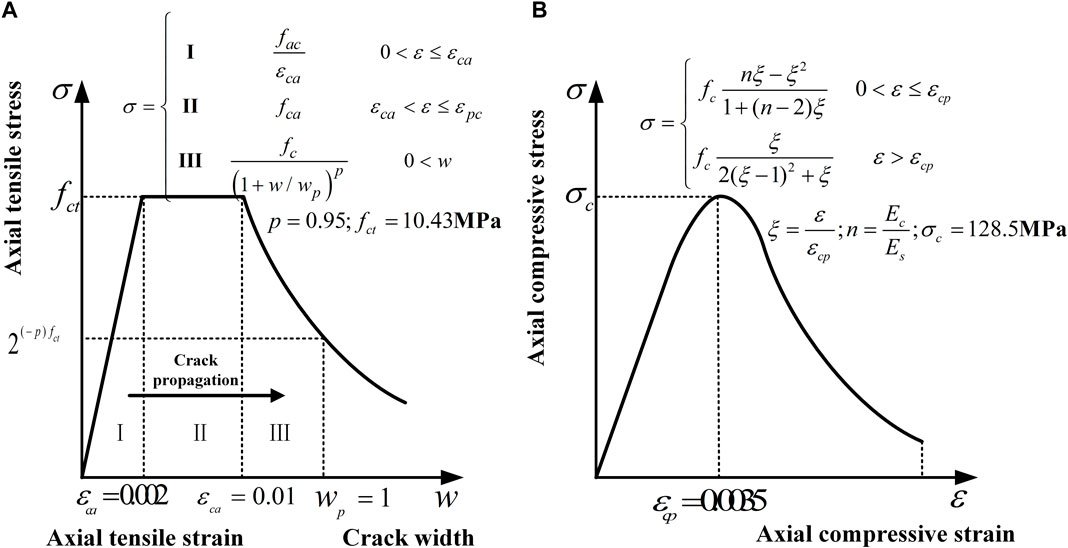
Figure 11. Stress-strain relationship of UHPC. (A) UHPC Tensile Constitutive Model; (B) Compresssive stress-strain relationship.
4.2.2 Steel
The steel material is primarily referenced from the existing literature (Cao and Shao, 2019), and the stress-strain curve is shown in Figure 12. Experimental results indicate that the steel plate undergoes yielding during the bending failure process of the composite bridge deck, thus a trilinear hardening elastic-plastic constitutive model is adopted for simulation. All steel components have a material strength grade of Q345, with a yield strength of 387.1 MPa, an ultimate strength of 542.3 MPa, and an elastic modulus of 202.2 GPa based on material testing results.
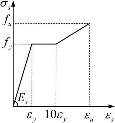
Figure 12. Stress-strain relationship of Steel.
4.2.3 Interfaces
The cohesive zone model is applicable for numerical analysis of the steel-concrete interface (Yin et al., 2019). Complex interface behaviors can be simulated by the traction-separation relationship of nodes in the cohesive elements (Ranz et al., 2020). In Figure 13, the thickness of the interface is much smaller than that of the composite bridge deck. Therefore, a cohesive contact behavior is employed to simulate the interface elements of the epoxy bonding layer. Additionally, referring to previous research, the shear stress-slip curve is bilinear (Zou et al., 2023a; Fang et al., 2024), suggesting that the cohesive model should adopt a bilinear stress-separation relationship. The stress-displacement relationship of the bonding elements can be determined by a bilinear traction-separation relationship, achieving the simulation of complex interface behavior in the local model, as detailed in Table 6.
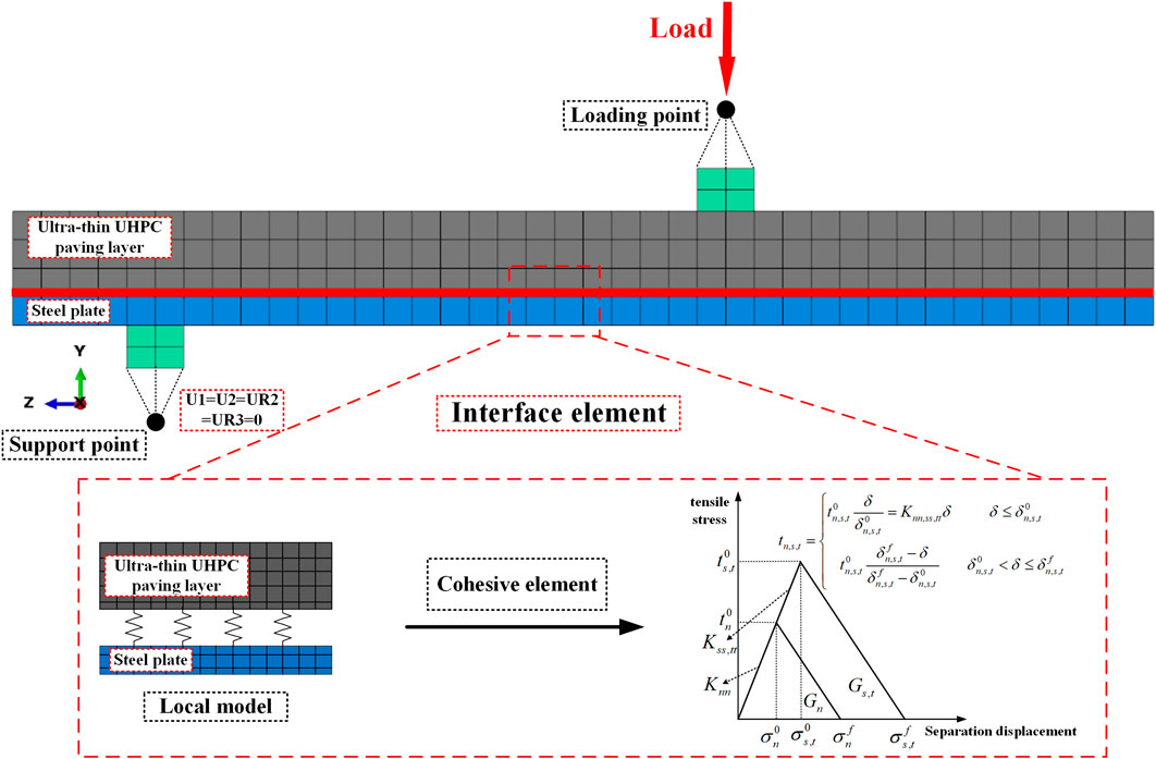
Figure 13. Constitutive model of cohesive element.
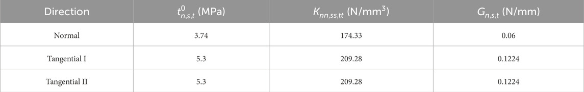
Table 6. Cohesion model ontology parameters.
4.3 Model validation
Figure 14 displays the load-deflection curves for both the EA-Lm and EA-J-Ln specimens (experimental and modeled). Both types of specimens exhibit good consistency in their curves. Compared to the experiment, the finite element model for the EA-Lm specimen exhibits debonding between the UHPC panel and the epoxy adhesive layer, while for the EA-J-Ln specimen, debonding occurs at the joint between the UHPC panel and the epoxy adhesive layer, with the area of failure being consistent. This indicates that the bending behavior of the composite bridge deck can be simulated by Cohesive Zone Model (CZM) to represent the bonding between the UHPC panel and the epoxy adhesive layer. The deviation between the experimental ultimate load and the model calculated value is within 5%, demonstrating that the finite element analysis can accurately simulate the bending behavior of the EA-Lm and EA-J-Ln specimens.
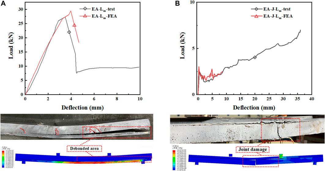
Figure 14. Model verification. (A) EA-Lm; (B) EA-J-Ln.
4.4 Discussion
Figure 15 presents the numerical simulation results of the EA-Lm and EA-J-Ln specimens. CSDMG is an indicator used to determine the degree of interface damage. When CSDMG reaches 1, it indicates delamination between the interface layers, and when its value ranges between 0 and 1, it signifies interface damage. DAMAGEC and DAMAGET represent the indices for evaluating compression and tensile damage in UHPC, respectively. Their values also range between 0 and 1, indicating damage to the UHPC matrix when they reach 1. According to Figure 15A, under the ultimate load Pu = 24.87 kN, there is extensive debonding between the epoxy adhesive layer and the UHPC panel, rendering them ineffective in working together. Additionally, significant tensile damage and minor compressive damage are observed near the loading point on the UHPC panel, but no destruction occurs. From Figure 15B, it can be seen that under the ultimate load Pu = 2.45 kN, extensive debonding occurs between the UHPC panel and the epoxy adhesive layer near the joint, while the UHPC matrix exhibits only minor tensile damage and no compressive damage.
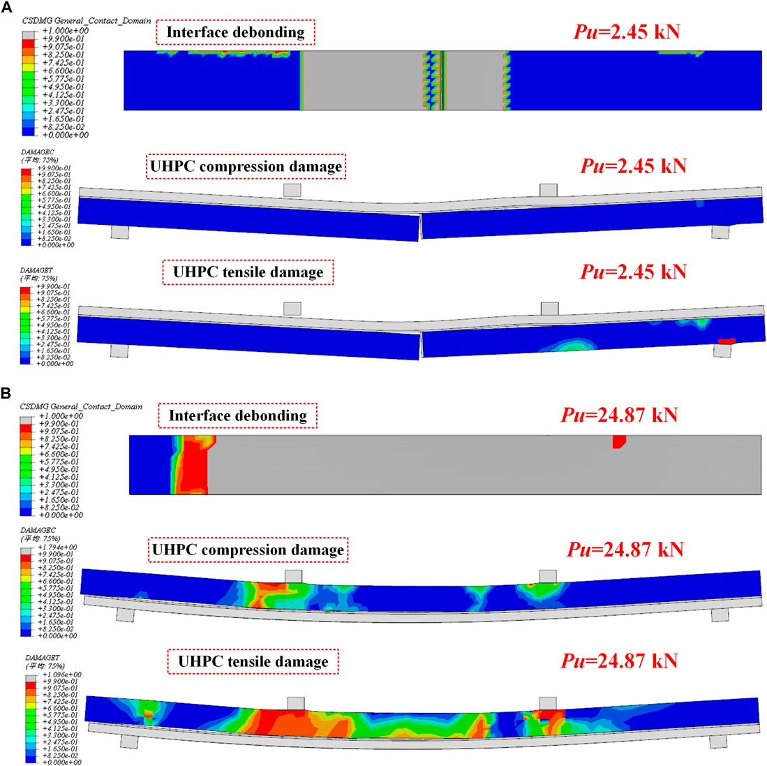
Figure 15. Numerical simulation results. (A) EA-Lm; (B) EA-J-Ln.
5 Conclusion
The following conclusions are drawn.
(1) For specimens using smooth surface UHPC bridge deck without joints under positive bending loading mode, the epoxy adhesive layer interface can provide a load-bearing capacity of approximately 27.67 kN. However, there is a risk of debonding between the UHPC panel and the epoxy adhesive layer, which prevents the full utilization of the material properties of UHPC. It is recommended to roughen the surface of prefabricated UHPC panels to ensure effective bonding with the epoxy adhesive layer.
(2) For specimens containing epoxy glue joints, under the negative bending moment loading mode, the interface damage first started at the joint position, and after the joint damage, the UHPC board close to the joint position and the epoxy adhesive layer debonded.
(3) Under the negative bending moment loading mode, the ultimate bearing capacity of the jointless specimen is 16.58 kN, which is about 6.5 times lower than the ultimate bearing capacity of the specimen containing epoxy joints.
(4) The use of carbon fiber cloth to enhance the epoxy glue joints can effectively improve the bending resistance of the joints and increase the ultimate bearing capacity by about 2 times. However, the width of the carbon fiber cloth has a significant impact on the bending performance of the composite plate joints.
(5) Establishing a numerical model for composite panels based on CZM can effectively simulate the bonding behavior between UHPC panels and steel plates. Using epoxy adhesive layers to connect steel plates with prefabricated UHPC bridge deck ensures more uniform stress transfer at the steel-UHPC interface. Additionally, the ultra-thin UHPC panel does not fail before interface failure occurs.
Data availability statement
The original contributions presented in the study are included in the article/Supplementary material, further inquiries can be directed to the corresponding author.
Author contributions
XZ: Data curation, Software, Validation, Visualization, Writing–original draft, Writing–review and editing. JJ: Conceptualization, Data curation, Investigation, Writing–original draft. LL: Investigation, Methodology, Writing–review and editing. SW: Methodology, Project administration, Writing–review and editing. XD: Software, Validation, Visualization, Writing–review and editing. YL: Formal Analysis, Investigation, Writing–review and editing. ZZ: Funding acquisition, Project administration, Resources, Supervision, Writing–review and editing, Writing–original draft.
Funding
The author(s) declare that financial support was received for the research, authorship, and/or publication of this article. The authors express their sincere gratitude for the financial support provided by the Natural Science Foundation of Chongqing, China (CSTB2023NSCQ-MSX0019), the National Nature Science Foundation of China (Grant Nos. 52208302, 52278293) and Science and Technology Research Program of Chongqing Municipal Education Commission (KJZD-M202300706).
Conflict of interest
The authors declare that the research was conducted in the absence of any commercial or financial relationships that could be construed as a potential conflict of interest.
Publisher’s note
All claims expressed in this article are solely those of the authors and do not necessarily represent those of their affiliated organizations, or those of the publisher, the editors and the reviewers. Any product that may be evaluated in this article, or claim that may be made by its manufacturer, is not guaranteed or endorsed by the publisher.
References
Ahmed, G. H., and Aziz, O. Q. (2019). Shear behavior of dry and epoxied joints in precast concrete segmental box girder bridges under direct shear loading. Eng. Struct. 182, 89–100. doi:10.1016/j.engstruct.2018.12.070
Benedetty, C. A., Dos Santos, V. B., Krahl, P. A., Rossi, A., Silva, F. D. A., Cardoso, D. C. T., et al. (2023). Flexural and shear behavior of steel-UHPC composite beams: a review. Eng. Struct. 293, 116649. doi:10.1016/j.engstruct.2023.116649
Bu, Y., Li, M., Wei, C., Cheng, Z., Cui, C., and Bao, Y. (2023). Experimental and analytical studies on flexural behavior of composite bridge decks with orthotropic steel deck and ultra-high-performance concrete (UHPC) slab under negative moment. Eng. Struct. 274, 115190. doi:10.1016/j.engstruct.2022.115190
Cao, J., and Shao, X. (2019). Finite element analysis of headed studs embedded in thin UHPC. J. Constr. Steel Res. 161, 355–368. doi:10.1016/j.jcsr.2019.03.016
Code for acceptance of construction quality of strengthening building structures (2010). Code for acceptance of construction quality of strengthening building structures (GB 50550-2010) [in Chinese].
Ding, J., Zhu, J., and Shi, T. (2023). Performance of grouped stud connectors in precast steel-UHPC composite bridges under combined shear and tension loads. Eng. Struct. 277, 115470. doi:10.1016/j.engstruct.2022.115470
Du, J., Meng, W., Khayat, K. H., Bao, Y., Guo, P., Lyu, Z., et al. (2021). New development of ultra-high-performance concrete (UHPC). Compos. B Eng. 224, 109220. doi:10.1016/j.compositesb.2021.109220
Du, L., Qi, J., Cheng, Z., and Wang, J. (2022). Finite element modeling of UHPC slabs with dovetail joints and steel wire mesh using an innovative interfacial treating method. Structures 37, 745–755. doi:10.1016/j.istruc.2022.01.057
Duan, L., Brühwiler, E., and Wang, C. (2020). Cold stiffening of orthotropic steel decks by a composite UHPFRC layer. J. Constr. Steel Res. 172, 106209. doi:10.1016/j.jcsr.2020.106209
Fang, Z., Wu, J., Xu, X., Ma, Y., Fang, S., Zhao, G., et al. (2024). Grouped rubber-sleeved studs–UHPC pocket connections in prefabricated steel–UHPC composite beams: Shear performance under monotonic and cyclic loadings. Eng. Struct. 305, 117781. doi:10.1016/j.engstruct.2024.117781
Fang, Z. C., Wu, J. P., Zhao, G. F., Fang, S., Ma, Y. H., and Jiang, H. B. (2024). Shear performance and design recommendations of single embedded nut bolted shear connectors in prefabricated steel–UHPC composite beams. Steel Compos. Struct. 50 (3), 319–336. doi:10.12989/scs.2024.50.3.319
Fang, Z., Fang, S., and Liu, F. (2022). Experimental and numerical study on the shear performance of short stud shear connectors in steel–UHPC composite beams. Buildings 12, 418. doi:10.3390/buildings12040418
General Administration of Quality Supervision (2010). Inspection and Quarantine, beijing, China. Metallic materials-Tensile testing-Part 1:Method of test at roomtemperature (GB/T 228.1-2010) ([in Chinese]).
General Administration of Quality Supervision (2015). Inspection and quarantine, beijing, China. Reactive powder concrete (GB/T 31387-2015) ([in Chinese]).
Hu, W., Li, C., Chen, B., and Liu, Y. (2023). Finite element analysis on shear behavior of headed studs in steel-UHPC composite slab. Structures 52, 464–475. doi:10.1016/j.istruc.2023.03.185
Hung, C.-C., El-Tawil, S., and Chao, S.-H. (2021). A review of developments and challenges for UHPC in structural engineering: behavior, analysis, and design. J. Struct. Eng. 147, 03121001. doi:10.1061/(asce)st.1943-541x.0003073
Jia, J., Ren, Z., Bai, Y., Li, J., Li, B., Sun, Y., et al. (2023). Tensile behavior of UHPC wet joints for precast bridge deck panels. Eng. Struct. 282, 115826. doi:10.1016/j.engstruct.2023.115826
Jiang, H., Chen, L., Ma, Z. J., and Feng, W. (2015). Shear behavior of dry joints with castellated keys in precast concrete segmental bridges. J. Bridge Eng. 20, 04014062. doi:10.1061/(ASCE)BE.1943-5592.0000649
Jiang, L., Nie, L., Zhou, W., Wu, X., and Liu, L. (2022). Distortional buckling analysis of steel-concrete composite box beams considering effect of stud rotational restraint under hogging moment. J. Cent. South Univ. 29, 3158–3170. doi:10.1007/s11771-022-5130-6
Khorramian, K., Maleki, S., Shariati, M., Jalali, A., and Tahir, M. M. (2017). Numerical analysis of tilted angle shear connectors in steel-concrete composite systems. Steel compos. Struct. 23, 067–085. doi:10.12989/scs.2017.23.1.067
Leng, J., Yang, J., Zhang, Z., Du, J., Zou, Y., and Zhou, J. (2024). Effect of vehicle-induced vibration on the strength, nano-mechanical properties, and microstructural characteristics of ultra-high-performance concrete during hardening process. Cem. Concr. Compos. 148, 105487. doi:10.1016/j.cemconcomp.2024.105487
Li, B., Jiang, J., Deng, Z., Zhou, H., Wang, H., Jiang, H., et al. (2022a). Bending behavior of steel-UHPC composite bridge deck based on epoxy adhesive. Front. Mater. 9. doi:10.3389/fmats.2022.1023886
Li, C., Chen, B., Hu, W., and Sennah, K. (2023a). Push-out test of hybrid shear connector in steel-precast UHPC composite slab. Structures 50, 1767–1782. doi:10.1016/j.istruc.2023.02.113
Li, Y., Ma, X., Li, H., Li, C., Hu, Z., and Li, Z. (2023b). Experimental study on flexural and interfacial shear properties of the steel-UHPC glued composite deck. Eng. Struct. 293, 116643. doi:10.1016/j.engstruct.2023.116643
Liu, Y., Bao, Y., Deng, L., and Zhang, Q. (2023). Numerical study on the effects of stud degradation and stud arrangement on the fatigue performance of steel-UHPC composite decks. Eng. Struct. 292, 116549. doi:10.1016/j.engstruct.2023.116549
Luo, Y., Li, A., and Kang, Z. (2012). Parametric study of bonded steel–concrete composite beams by using finite element analysis. Eng. Struct. 34, 40–51. doi:10.1016/j.engstruct.2011.08.036
Men, P., Di, J., Qin, F., and Su, Y. (2023). Experimental investigation of the shear behavior of slender continuous steel–concrete composite girders in hogging moment. J. Struct. Eng. 149, 04022218. doi:10.1061/JSENDH.STENG-11537
Pan, R., He, W., Cheng, L., Su, M., and Li, C. (2023). Experimental investigation on the shear performance of UHPC large-keyed epoxy joints subjected to direct shear loading. Structures 54, 171–182. doi:10.1016/j.istruc.2023.05.050
Pang, B., Jin, Z., Zhang, Y., Xu, L., Li, M., Wang, C., et al. (2022). Ultraductile waterborne epoxy-concrete composite repair material: epoxy-fiber synergistic effect on flexural and tensile performance. Cem. Concr. Compos. 129, 104463. doi:10.1016/j.cemconcomp.2022.104463
Ranz, D., Cuartero, J., Castejon, L., Miralbes, R., and Malon, H. (2020). A cohesive zone model approach to interlaminar behaviour of carbon/epoxy laminated curved beams. Compos. Struct. 238, 111983. doi:10.1016/j.compstruct.2020.111983
Shao, X., Qu, W., Cao, J., and Yao, Y. (2018). Static and fatigue properties of the steel-UHPC lightweight composite bridge deck with large U ribs. J. Constr. Steel Res. 148, 491–507. doi:10.1016/j.jcsr.2018.05.011
Shi, Z., Su, Q., Kavoura, F., and Veljkovic, M. (2022). Behavior of short-headed stud connectors in orthotropic steel-UHPC composite bridge deck under fatigue loading. Int. J. Fatigue 160, 106845. doi:10.1016/j.ijfatigue.2022.106845
State Administration for Market Regulation (2021). Standardization Administration, beijing, China. Test methods for properties of resin casting body (GB/T 2567-2021) ([in Chinese]).
Sun, N., Song, Y., Hou, W., Zhang, H., Wu, D., Li, Y., et al. (2021). Interfacial bond properties between normal strength concrete and epoxy resin concrete. Adv. Mater. Sci. Eng. 2021, 1–14. doi:10.1155/2021/5561097
Wang, Y., Shao, X., Chen, J., Cao, J., and Deng, S. (2021). UHPC-based strengthening technique for orthotropic steel decks with significant fatigue cracking issues. J. Constr. Steel Res. 176, 106393. doi:10.1016/j.jcsr.2020.106393
Wang, Z., Nie, X., Fan, J.-S., Lu, X.-Y., and Ding, R. (2019). Experimental and numerical investigation of the interfacial properties of non-steam-cured UHPC-steel composite beams. Constr. Build. Mater. 195, 323–339. doi:10.1016/j.conbuildmat.2018.11.057
Yin, H., Shirai, K., and Teo, W. (2019). Numerical model for predicting the structural response of composite UHPC–concrete members considering the bond strength at the interface. Compos. Struct. 215, 185–197. doi:10.1016/j.compstruct.2019.02.040
Yoo, D.-Y., Min, K.-H., Lee, J.-H., and Yoon, Y.-S. (2014a). Shrinkage and cracking of restrained ultra-high-performance fiber-reinforced concrete slabs at early age. Constr. Build. Mater.73, 357–365. doi:10.1016/j.conbuildmat.2014.09.097
Yoo, D.-Y., Park, J.-J., Kim, S.-W., and Yoon, Y.-S. (2014b). Influence of reinforcing bar type on autogenous shrinkage stress and bond behavior of ultra high performance fiber reinforced concrete. Cem. Concr. Compos. 48, 150–161. doi:10.1016/j.cemconcomp.2013.11.014
Yu, K., Zhang, Z., Zou, Y., Jiang, J., Zeng, X., and Tang, L. (2022). Interfacial shear performance of epoxy adhesive joints of prefabricated elements made of ultra-high-performance concrete. Polymers 14, 1364. doi:10.3390/polym14071364
Zhang, B., Yu, J., Chen, W., Sun, H., Chen, S., and Wang, H. (2022). Interfacial properties between ultra-high performance concrete (UHPC) and steel: from static performance to fatigue behavior. Eng. Struct. 273, 115145. doi:10.1016/j.engstruct.2022.115145
Zhang, P., Xu, F., Peng, E., Liu, Y., and Sheikh, S. A. (2023a). Shear performance of the epoxy-bolt interface between UHPC slabs and GFRP girder. Structures 54, 263–279. doi:10.1016/j.istruc.2023.05.014
Zhang, Z., Pang, K., Xu, L., Zou, Y., Yang, J., and Wang, C. (2023b). The bond properties between UHPC and stone under different interface treatment methods. Constr. Build. Mater. 365, 130092. doi:10.1016/j.conbuildmat.2022.130092
Zou, Y., Jiang, J., Yang, J., Zhang, Z., and Guo, J. (2023a). Enhancing the toughness of bonding interface in steel-UHPC composite structure through fiber bridging. Cem. Concr. Compos. 137, 104947. doi:10.1016/j.cemconcomp.2023.104947
Zou, Y., Jiang, J., Zhou, Z., Wang, X., and Guo, J. (2021a). Study on the static performance of prefabricated UHPC-steel epoxy bonding interface. Adv. Civ. Eng. 2021, 1–15. doi:10.1155/2021/6663517
Keywords: ultra-high-performance concrete (UHPC), bridge deck joints, epoxy adhesive, flexural performance, numerical simulation
Citation: Zhou X, Jiang J, Liu L, Wang S, Deng X, Li Y and Zhang Z (2024) Bending performance of prefabricated ultra-thin UHPC unit plate reinforced orthotropic steel bridge decks. Front. Mater. 11:1380316. doi: 10.3389/fmats.2024.1380316
Received: 01 February 2024; Accepted: 01 March 2024;
Published: 26 March 2024.
Edited by:
Zhigang Zhang, Chongqing University, ChinaCopyright © 2024 Zhou, Jiang, Liu, Wang, Deng, Li and Zhang. This is an open-access article distributed under the terms of the Creative Commons Attribution License (CC BY). The use, distribution or reproduction in other forums is permitted, provided the original author(s) and the copyright owner(s) are credited and that the original publication in this journal is cited, in accordance with accepted academic practice. No use, distribution or reproduction is permitted which does not comply with these terms.
*Correspondence: Zhongya Zhang, zhangzhongya@cqjtu.edu.cn