A novel design of hard-magnetic soft switch array for planar and curved surface applications
 Po Yang1
  Bin Huang
- 1Smart Materials and Advanced Structures Laboratory, Faculty of Mechanical Engineering and Mechanics, Ningbo University, Ningbo, China
- 2College of Science and Technology, Ningbo University, Ningbo, China
- 3AECC Hunan Aviation Powerplant Research Institute, Zhuzhou, China
This paper proposes an array structure with multidirectional remanent magnetization based on hard-magnetic soft materials, which can be used as a soft switch array on planar and curved surfaces. We firstly investigate the displacement response of a hard-magnetic soft switch which is excited by a magnetic field, and related to the magnitude and direction of the magnetic field. When the remanent magnetization direction of the soft switch is opposite to the horizontal component of the magnetic field, the displacement response is greater than that of the driving magnetic field in other directions. The maximum displacement of the soft switch can reach 4.5 mm under a 6 V driving voltage applied to the Helmholtz coil. We further design 2 × 2 and 3 × 3 switch arrays and the circuit structures of the switch arrays. The switch arrays are fabricated, and the displacement responses of the switch arrays under different driving magnetic fields on planar and curved surfaces are finally demonstrated. When the Z-axis displacement of the device reaches more than 3 mm, the LED light can be switched on. The hard-magnetic soft switch array structure designed in this paper can enable the application of soft switches in curved environments, verifying the feasibility of the application of hard-magnetic soft switch arrays. It is expected to provide a guidance for the design and manufacturing of multi-functional hard-magnetic soft switches in the future and the application of hard-magnetic soft switch arrays in planar and curved environments.
1 Introduction
Switches are widely used in various scenarios and will tend to be diversified and intelligent (Li and Wu, 2008; Ghosh and Atkinson, 2023; Jurik and Sokol, 2023). However, currently most switch materials are too hard, have poor flexibility, and impact resistance (Lin and Huang, 2023; Marcelli and Sardi, 2023). Therefore, the flexibility and environmental adaptability of switches are a challenge in this field. In recent years, responsive soft materials can undergo reversible, complex, and rapid shape changes under external stimuli. They have obvious advantages in flexibility, adaptability, and scalability, and their potential applications in fields such as bioengineering, biomimetics, automation, and industry are increasingly receiving attention (Martinez and Glavan, 2014; Mosadegh and Polygerinos, 2014; Athas and Nguyen, 2016). Compared with traditional switches, responsive soft materials have higher flexibility, environmental adaptability and simpler design, and are expected to be applied in the design and fabrication of switches.
Responsive soft materials can respond to stimuli such as air pressure (Rehman and Faudzi, 2017; Robertson and Paik, 2017) electric field (Gu and Zou, 2018; Weng and Duan, 2020) light (da Cunha and Ambergen, 2020a; da Cunha and Debije, 2020b) and magnetic field (Song and Lee, 2020; Ze and Kuang, 2020). For example, Jiao et al. (Jiao and Ji, 2019) designed a new type of vacuum driven soft pneumatic torsion actuator, demonstrating the feasibility of its application in fields such as flexible joints and rotating crawling robots. Zhu et al. (Zhu and Xie, 2020) developed a new manufacturing method for soft robots with self-powered sensors based on triboelectricity. Ahn et al. (Ahn and Liang, 2019) designed a light driven soft robot that can crawl on the ground, squeeze through a small channel and jump over an obstacle. For these actuating systems, each additional degree of freedom requires an additional transmission system, which poses challenges to the flexibility and miniaturization of responsive soft materials. In recent years, magnetic field driven devices have been widely used in the field of soft robots due to its advantages of non-contact control, rapid response capability and programmable control (Chen and Hoop, 2017; Cao and Fan, 2020; Jiang and Liu, 2022). Kim et al. (Kim and Parada, 2019) developed a submillimeter scale self-lubricating soft continuum robot with omnidirectional steering and navigation capabilities based on magnetic actuation. The ultrafast small-scale electromagnetic soft robot developed by Mao et al. (Mao and Schiller, 2022) can achieve functions such as walking, running, swimming, and jumping.
In the field of switches, a large number of magnetic field driven switches have been developed (Cho and Lee, 2012; Zhang Y. and Liu, 2013), which are easy to install and achieve multi-point control. However, the application in curved environments and flexible electronic devices is often limited by the reliance on structures composed of rigid magnets and transmission parts. Therefore, compared to the contact control and fixed application scenarios of traditional switches, magnetic soft materials driven by magnetic fields can achieve non-contact control and are suitable for curved environments. To prepare magnetic soft materials, the general strategy is to embed small magnetic particles into the soft material (Lu and Sim, 2024), and then mix the magnetic particles with the soft material to obtain a magnetic mixed solution. Due to the distribution of magnetic particles in soft materials, the entire structure has magnetism, and magnetic soft materials with different magnetic particle contents can be easily designed and prepared. The magnetization of magnetic soft materials causes ordered arrangement of disordered magnetic domains inside, such as assembly magnetization (Diller and Sitti, 2014; Zhang and Onaizah, 2017; Wu and Ze, 2019), template assisted magnetization (Hu and Lum, 2018; Venkiteswaran and Samaniego, 2019; Manamanchaiyaporn and Xu, 2020), magnetic field assisted magnetization (Kim and Yuk, 2018; Xu and Zhang, 2019; Alapan and Karacakol, 2020), etc. This work uses the last magnetization strategy, which has the most promising application prospects in high-precision and flexible magnetic devices, and can be achieved through 3D printing, ultraviolet (UV) lithography and heating. Hard-magnetic soft materials form anisotropic magnetization profiles after magnetization (Kim and Chung, 2011; Deng and Sattari, 2020; Ju and Hu, 2021) and due to this anisotropy, a magnet generates magnetic forces and torques in different directions under the action of the driving magnetic field, resulting in a single shape change. By adopting different magnetization directions and designing array structures, the disadvantage of single control of a soft magnet can be solved, which can be applied to the design of magnetic field driven, flexible and array based hard-magnetic soft intelligent devices.
Based on the above, this paper will propose a design method for hard-magnetic soft switch arrays with different magnetization directions and apply it to the planar and curved surfaces. Firstly, in order to study the characteristics of hard-magnetic soft materials, we prepare the hard-magnetic soft materials and investigate the elastic and magnetic properties of hard-magnetic soft materials through tensile tests and magnetostrictive loop tests. The displacement responses of soft switches under different magnetic fields are also calculated by using COMSOL, which can provide the theoretical guidance for the design of hard-magnetic soft switches. Secondly, we design 2 × 2 and 3 × 3 hard-magnetic soft switch arrays which are composed of multiple soft switches with different magnetization directions and connection methods. Their magnetic responses in planar and curved installation environments are investigated by the experimental test results and compared with the finite element calculation results. The feasibility of applying hard-magnetic soft switch arrays on planar and curved surfaces is verified through LED lighting experiments. Compared with traditional switches, hard-magnetic soft switch arrays have the advantages of programmable control, non-contact control, anti-interference ability and diverse installation environments, which can be applied in fields such as sensing, flexible electronic devices, and industrial manufacturing in the future.
2 Material preparation and characterization results
Hard-magnetic soft materials are important components of soft switches, which will exhibit shape transformations under the action of magnetic fields. The deformation ability of hard-magnetic soft materials depends on their elastic and magnetic properties. Therefore, the preparation, tensile testing, magnetic performance testing, and finite element analysis of hard-magnetic soft materials are firstly investigated.
2.1 Preparation of soft magnets
The hard-magnetic soft material applied to soft switches consists of soft material and hard-magnetic particles. The soft material requires low modulus and low density. This work uses Polydimethylsiloxane (PDMS) (Sylgard 184, Wenhao Co., Ltd) as the matrix material, whose flexible mechanical properties ensure desired deformation and recovery of hard-magnetic soft materials. Magnetic materials need to have strong magnetism and high coercivity to ensure that they can generate sufficient displacement and deformation under the driving force of the magnetic field. Thus, we choose isotropic bonded Neodymium Iron Boron magnetic powder (NdFeB) (LW-C-400, NUODE, Ltd) as the magnetic material in this work, with an average diameter of 5 µm and a high remanence rate, which can ensure stable and reliable response under magnetic field.
The preparation method of NdFeB/PDMS soft magnets is mold casting, as shown in Figure 1. The soft magnets are the magnetized soft samples, but with hard-magnetic particles in this work. Firstly, the prepolymer and crosslinking agent were mixed in the experimental cup at a volume ratio of 10:1 to prepare the PDMS mixed solution, and stirred thoroughly. Weighing a certain amount of NdFeB powder and PDMS mixed solution by using an electronic scale and stirring it for 5 min, the two materials were fully mixed. The stirred mixed solution was poured into the 3D printed Polytetrafluoroethylene (PTFE) mold. Then, the mold was placed in an oven for drying and curing to obtain PDMS elastomer. For curing the samples, two curing temperatures are chosen (25°C and 120°C) and the curing time are 24 h and 30 min for them. By demoulding the solidified NdFeB/PDMS magnets from the mold, the soft magnets were formed. Finally, using the magnetizer (MA-3050, Jiujuok Co., Ltd), the soft magnets were subjected to the directional magnetization to possess magnetic properties with different remanent magnetization directions.
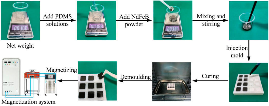
FIGURE 1. Preparation process of soft magnet.
2.2 Tensile test
In order to investigate the mechanical properties of hard-magnetic soft materials, a tensile testing machine (AGS-X-10KN, Shimadzu, Ltd) was used to conduct tensile tests on the hard-magnetic soft materials. The strain-stress curves were measured before magnetization, since the strain of each soft magnet is small in the switch design, and the Young’s modulus changes slightly after magnetization at low strain condition (Garcia-Gonzalez and Ter-Yesayants, 2023). The effects of temperature and magnetic powder mass ratio on the tensile strength, elastic modulus, and elongation at break of the hard-magnetic soft materials were studied. To prepare the experimental materials, we used the preparation method shown in Figure 1 to prepare the hard-magnetic soft material samples with the NdFeB/PDMS mass ratios of 1, 1.25, 1.5, 1.75 and 2, respectively. We divided the samples into two groups which were cured at the temperatures of 25°C and 120°C. The size of the samples for tensile test is 70 mm × 5 mm × 1 mm. The upper and lower ends of the samples were clamped in the tensile machine for a length of 10 mm, so that the effective stretching length is 50 mm. During the tensile process, the stretching speed was set to be 10 mm/min, and the stretching parameters were read and recorded using the stress sensors and displacement sensors. Finally, we obtained the strain-stress curve, as shown in Figure 2.
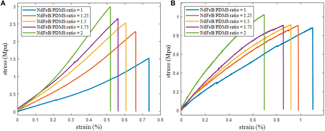
FIGURE 2. Strain-stress curves of tensile test for soft magnet samples at different temperatures, (A) T = 25°C; (B) T = 120°C.
In Figure 2, the tensile strength, elongation at break, and elastic modulus can be obtained from the strain-stress curves of NdFeB/PDMS hard-magnetic soft samples with different mass ratios. When the temperature is 25°C, with the increase of NdFeB mass ratio, the tensile strength and elastic modulus of the soft magnet increase, while the elongation at break decreases. This is because as the content of NdFeB increases, the density of NdFeB powder dispersed in the matrix increases, resulting in an increase in the strength of the NdFeB/PDMS sample. Under the same NdFeB content, as the curing temperature increases, the tensile strength and elastic modulus of the sample also increase, while the elongation at break decreases. This is because the higher the temperature, the greater the degree of crosslinking that will affect the mechanical properties of the final matrix (Johnston and McCluskey, 2014). Due to the smaller elastic modulus of soft magnets cured at 25°C, they can undergo larger deformation than the samples cured at 120°C under the same driving force of a magnetic field. When the tensile strain ranges from 0 to 0.1, the stress shows an approximate linear growth trend. At this range, the Young’s moduli of the soft magnets with NdFeB/PDMS mass ratios of 1, 1.25, 1.5, 1.75 and 2 are 1.14 MPa, 1.32 MPa, 1.49 MPa, 1.6 MPa and 2.17 MPa, respectively. Therefore, based on the magnetic field conditions and deformation requirements in this work, soft magnets cured at 25°C are chosen as the switch material.
2.3 Magnetic properties
In this work, two magnetization directions to magnetize the soft magnets were used, namely magnetization in parallel to the edge of rectangular sample and magnetization in diagonal. The magnetizing voltage is 3000 V and the capacitance is 5000 µF. The Tesla meter can be used to measure the magnetic induction intensity of soft magnets with different mass ratios. In the preparation of switch arrays in the following section, the magnetic induction intensity of the soft magnet will be measured and samples with significant differences in magnetic properties will be removed. Soft magnets with a more regular body shape and a closer magnetic induction intensity will be selected. We used a vibrating sample magnetometer (Lake Shore 7404, Lake Shore Inc.) to measure the hysteresis loops of the samples and investigated the effect of mass ratio on the saturation magnetization and remanent magnetization strengths of soft magnets. Figure 3 shows the hysteresis loops of soft magnet samples with NdFeB/PDMS mass ratios of 1 and 2. Samples of both mass ratios were tested three times to ensure the accuracy of the test results. When the external magnetic field is 20 kOe, the saturation magnetization strengths of soft magnets with the mass ratio of 1 and 2 are 62 emu/g and 88 emu/g, respectively. When the external magnetic field decreases to 0, its remanent magnetization strength is 40 emu/g and 60 emu/g, respectively. Thus, the magnetism of hard-magnetic soft materials is related to the content of magnetic particles, and the remanent magnetization strength and coercive force of NdFeB magnetic particles are relatively high, making them difficult to be magnetized and demagnetized under the action of external magnetic fields.
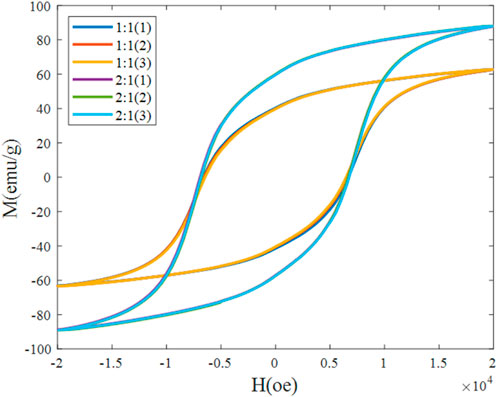
FIGURE 3. Hysteresis loops of the samples.
In Figure 4, the red arrows indicate the directions of remanent magnetization. The soft magnet and the connecting body are bonded to form a single unit. Firstly, we prepared different proportions of NdFeB/PDMS soft magnets and PDMS connectors which are laid on a clean glass plate. Using K704 silicone sealant, the two PDMS connectors are glued on both sides of the soft magnet. Due to the presence of NS poles in soft magnets, to achieve better displacement response of hard-magnetic soft structures, the PDMS connectors are required to be glued on both sides of the N-pole of the soft magnet in order to ensure that the PDMS connectors are connected to the position where the polarity of the soft magnet is same. The soft magnet adopts two connection methods, namely opposite edge connection (OEC) and adject edge connection (AEC), as shown in Figure 4. The size of each soft magnet is 10 mm × 10 mm × 1 mm, the size of PDMS connector is 5 mm × 3 mm × 0.4 mm.

FIGURE 4. Design and assembly of hard-magnetic soft switch array.
In order to study the displacement responses of soft magnets, a magnetic field driven experimental platform was constructed in this work, as shown in Figure 5A. It mainly consists of the programmable DC power supply (DP811A, Rigol, Ltd), Helmholtz coil (PS-1HM330, Paisheng, Ltd), aluminum bracket, experimental platform, etc. The programmable DC power supply provides a stable voltage to the Helmholtz coil, causing it to generate a static magnetic field. The maximum power supply range of the programmable DC power supply is 20V/10A. The uniform magnetic field area generated by the Helmholtz coil is 50 mm × 50 mm × 50 mm. Fixing a 45° aluminum bracket below the Helmholtz coil, the direction of the magnetic field generated by the coil forms a 45° angle with the z-axis. Figure 5B shows the magnetic field in the uniform area of the coil generated under the applied voltage, which is linear. Figure 6 shows the displacement responses of the soft magnet under different driving voltages and their maximum displacements are shown in Figure 7. Under the connection condition of AEC, when the mass ratio of NdFeB/PDMS soft magnet is 2, its upward displacement response increases rapidly, as shown in Figure 6B. When the driving voltage is 4.5 V, the displacement of the Z-axis is approximately 8.5 mm. Under the condition of OEC, when the NdFeB/PDMS mass ratio of the soft magnet is 1, its upward displacement response increases slowly, as shown in Figure 6C. When the driving voltage is 8 V, the displacement of the Z-axis is approximately 1.2 mm. In addition, it can be observed that when the NdFeB/PDMS mass ratio of the soft magnet under AEC condition is 1, as shown in Figure 6A, and under OEC condition is 2, as shown in Figure 6D, its upward displacement response increases slowly for the voltage below 5 V. When the driving voltage is 5 V, their Z-axis displacement responses are approximately 1.5 mm and 2.8 mm. When the driving voltage increases to 6 V, namely the magnetic field is about 25.4G, the displacements of the Z-axis are about 4.5 mm and 4.2 mm, respectively. Therefore, when the mass ratios of NdFeB/PDMS soft magnets connected by AEC and OEC are 1 and 2, respectively, the Z-axis displacements of the soft magnets are relatively close, and their magnetic induction strengths are about 148G and 342G, respectively. Therefore, from the experimental results of soft magnets, it can be found that the connection method has a significant impact on the displacements of the soft magnets, and the influence of the connection method needs to be considered in the switch design.
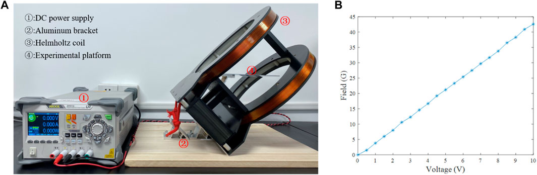
FIGURE 5. (A) Experimental testing platform; (B) Voltage-magnetic field relation of the Helmholtz coil.
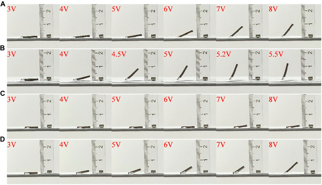
FIGURE 6. Displacement responses of the soft magnets for different mass ratios and connection methods, (A) AEC, mass ratio = 1, (B) AEC, mass ratio = 2, (C) OEC, mass ratio = 1, (D) OEC, mass ratio = 2.
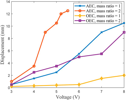
FIGURE 7. Maximum displacements of the soft magnets for different mass ratios and connection methods.
2.4 Finite element analysis
In order to study the relationship between the displacement responses of soft magnets and the directions of magnetic field, we performed the finite element analysis in this section by commercial package COMSOL. In the finite element simulation, the geometric model of the soft magnet was firstly established, including the soft magnet, connecting body, fixed base and air domain, and a three-dimensional spatial model and steady-state study were chosen for analysis. Two physical models were involved in the model: solid mechanics and magnetic field without current. Due to the consideration of the weight of the soft magnet, the tensile force of the connecting body, and the magnetic force of the magnetic field, appropriate boundary conditions need to be set in the physical model. To reduce the computational complexity of simulation, applying a magnetic scalar potential to a soft magnet can make the model simpler. The magnetic field is applied by defining a computational domain for the surrounding space and specifying the magnetic flux density for it. The tetrahedron element is used for the present 3-D model and the mesh is small enough to obtain convergent results. Based on the stress-strain curve we measured and the minimal deformation under magnetic field, we chose an elastic modulus with a strain range of 0–0.1. The stress-strain curve in this interval is approximately linear, so we obtained the elastic model based on the slope. For a more accurate constative model, a microstructural magneto-mechanical coupling using a homogenization model can be adopted (Moreno-Mateos et al., 2022). Thus, in the finite element model, two NdFeB/PDMS mass ratios 1 and 2 are considered and their corresponding mass densities are 1.7 g/cm3 and 2.2 g/cm3, corresponding Young’s moduli are 1.14 MPa and 2.17 MPa, and corresponding remanent magnetization strengths are 40 kA/m and 60 kA/m. The Young’s moduli of the connectors for both connection cases are 0.62 MPa, and the applied magnetic field is 55G. It should be noted that the applied field is considered to be uniform since the soft magnet works within the space with unform field generated by the coil. For a more accurate simulation of the field, all magnetic sources have to be considered in the modeling, instead of using a uniform field (Moreno-Mateos et al., 2023). When the magnetic fields with different directions are applied but 45° from the Z-axis, the displacement response of the soft magnet varies significantly, as shown in Figure 8. The red arrow in the Figure represents the remanent magnetization direction of the soft magnet. The angle value marked in Figure 8 are the angles between the direction of the projection of the applied magnetic field on the horizontal plane (XY) and the remanent magnetization direction of the soft magnet. When the angle is 180°, that is, the projection of the applied magnetic field is opposite to the remanent magnetization direction. The upward force of the magnetic field can overcome the gravity of the soft magnet, and the magnet moves upward, reducing the angle between the remanent magnetization direction and the applied magnetic field direction and maximizing the displacement. In Figure 8, it can be observed that the AEC soft magnets for the mass ratios 1 and 2 generate displacement responses of 5.9 mm and 8.8 mm, respectively, as shown in Figure 8A, B. While the OEC soft magnets for the mass ratios 1 and 2 generate much smaller displacement responses that are 1.5 mm and 4.1 mm, respectively as shown in Figure 8C, D. This implies that the AEC condition restricts the vertical motion of the magnet much less than that of the OEC condition. As the angle decreases, their displacement response also decreases significantly. Therefore, when the angle between the magnetic field and the Z-axis is 45°, and the projection of magnetic field in the horizontal plane is opposite to the remanent magnetization direction of the soft magnet, the displacement response of the soft magnet is the largest, which can be clearly distinguished from the effects of other directions of magnetic fields.
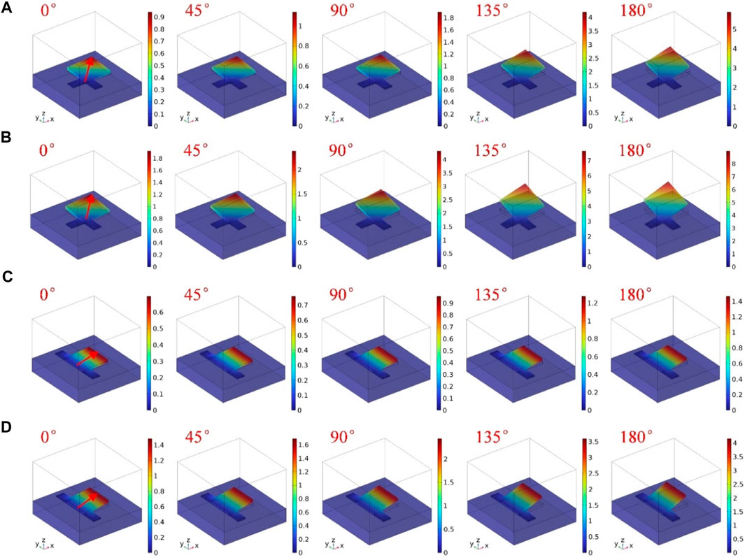
FIGURE 8. Relationship between the displacement responses of soft magnets and different magnetic field directions, (A) AEC, mass ratio = 1, (B) AEC, mass ratio = 2, (C) OEC, mass ratio = 1, (D) OEC, mass ratio = 2.
3 Design and fabrication of hard-magnetic soft switch arrays
3.1 Design and fabrication of 2 × 2 and 3 × 3 planar hard-magnetic soft switch arrays
The previous section studied the displacement responses of soft magnets under the action of magnetic fields through preparation, experimental testing, and finite element analysis. Soft magnets exhibit complex displacement responses under magnetic fields, with different displacement responses influenced by the direction of the magnetic field. This section will further design and prepare hard-magnetic soft switch arrays based on the response characteristics of the soft magnets, and explore their application feasibility in planar structures. To demonstrate the potential application of the proposed hard-magnetic soft switch, 2 × 2 and 3 × 3 array structures were designed with multiple remanent magnetization directions.
For the 2 × 2 and 3 × 3 array structures, as shown in Figure 4, it includes the individual magnet unit, polyvinylchloride (PVC) base, rubber support and circuit diagram. The 2 × 2 switch array is mainly composed of four hard-magnetic soft switches with the same magnetization direction. The 3 × 3 switch array mainly consists of 8 hard-magnetic soft switches with two different remanent magnetization directions and connection methods. The middle position in 3 × 3 switch array is temporarily not used as a switch. Similarly, we used K704 as the bonding material for the hard-magnetic soft switch array, which is used to bond and fix PDMS connectors and soft magnets to prevent interference from the displacement responses of adjacent soft magnets. Due to the different displacement responses of hard-magnetic soft switches under different magnetic fields, different soft magnets in hard-magnetic soft switch arrays also have different displacement responses. Therefore, the displacement responses of different switches under a magnetic field are different, and the closure of single or multiple switch circuits can be achieved through the control of magnitude or direction of the magnetic field, achieving programmable control capabilities. The magnetic field applied to the switch array is generated by the Helmholtz coil, which generates a static uniform magnetic field under the DC voltage, as shown in Figure 5A. We chose PVC material as the base and circuit fixing platform for the hard-magnetic soft switch array. In order to ensure good conductivity of the circuit and stable fixation on the PVC board, we used copper tape as the circuit and set multiple breakpoints (with an interruption distance of 1 mm) above the soft magnets. Finally, the copper tape was also attached on the soft magnet for closing the circuit (approximately 4 mm × 4 mm), and the circuit is powered by a lithium battery.
The experimental process of a planar hard-magnetic soft switch array is as follows. Firstly, we fixed the hard-magnetic soft switch array on a PVC base, and used four support rubbers with a height of 4 mm at the four corners of the base. Then, we fixed a PVC board bonded with copper circuit above the support rubbers. For 2 × 2 and 3 × 3 planar hard-magnetic soft switch arrays, we carried out the experiment under Helmholtz coils. We marked a fixed position on the working platform of the coil, so that the magnitude and direction of the magnetic field applied to the soft magnets at that position are consistent in different experiments. Then, the hard-magnetic soft switch array was placed on the working platform. Since the magnetic field direction of the coil is fixed, the position and direction of the hard-magnetic soft switch array need to be adjusted for each test, so that the remanent magnetization direction of the test magnet is opposite to the direction of the magnetic field component in the horizontal plane. In the experiment, the driving voltage was slowly increased through the programmable DC power supply, and the corresponding soft magnet slowly moved upwards. According to the simulation analysis in Figure 9, the maximum displacement generated by the working soft magnet in the ×22 switch array is 4.1 mm, while the displacement of the remaining soft magnets is only 1.3 mm, which allows the application of a magnetic field to control the closure of a single switch. In the simulation analysis of 3 × 3 switch array, when the soft magnets in the middle and corner are the working magnets, their displacement responses are 3.9 mm and 4.5 mm, respectively, while the maximum displacement responses generated by the other soft magnets are 3 mm and 3.4 mm, with little difference between the two.
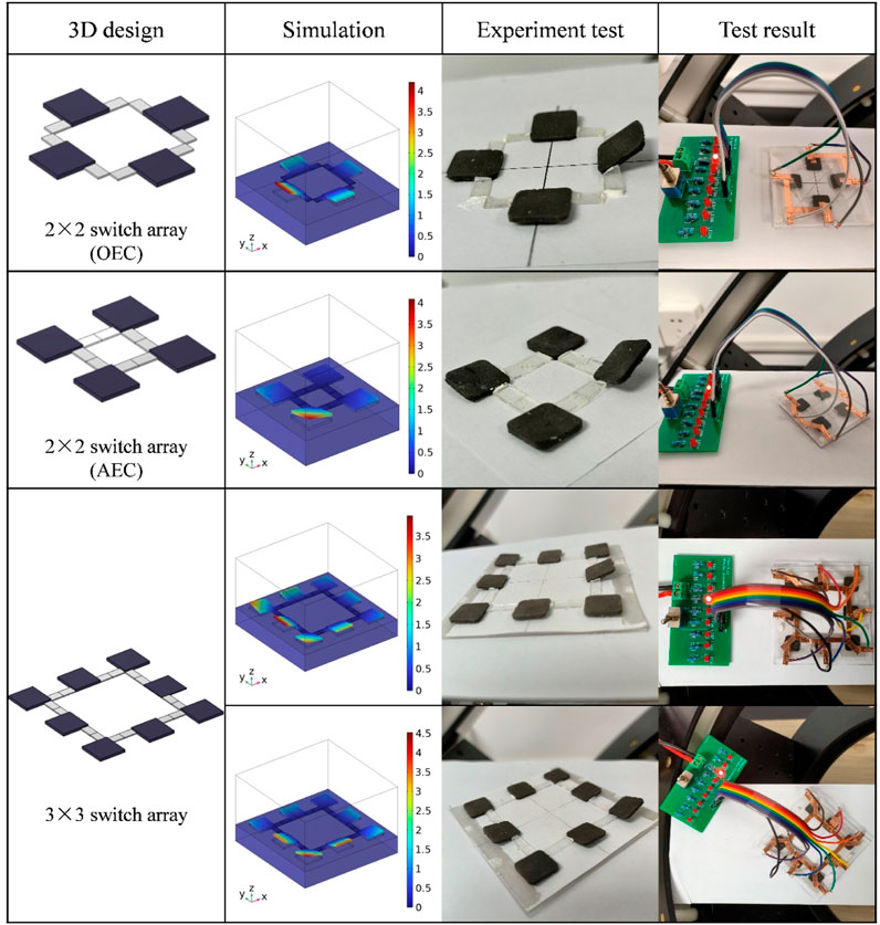
FIGURE 9. Hard-magnetic soft switch array for the planar surface applications.
The 3rd column in Figure 9 shows the switch displacement responses in the experimental tests, while the 4th column shows the switch test results. The experimental and simulation results have been verified. Due to the height of the supporting rubber being 4 mm and the thickness of the soft magnet itself being 1 mm, when the upward displacement of the soft magnet reaches more than 3 mm, the copper tape on the soft magnet contacts the copper tape at the circuit interruption point, causing the circuit to conduct and the corresponding LED light to light up. However, the copper tape on the soft magnet and the copper tape at the circuit break need to reach a certain contact force to make the circuit conductive. Therefore, when the displacement of the soft magnet on the Z-axis is 3 mm, the actual driving voltage required will be greater than the theoretical driving voltage. Additionally, due to the fact that each soft magnet (adjacent edges or corners) in the ×33 switch array is affected differently by the magnetic field, and the displacement difference is smaller compared with ×22 array, the remanent magnetization strength of the soft magnets and the modulus parameters of the connecting body should be consistent as much as possible to facilitate more refined control.
3.2 Design and fabrication of 2 × 2 and 3 × 3 curved hard-magnetic soft switch arrays
This section investigates the application of hard-magnetic soft switch arrays on curved surfaces. Due to the changes of the angle between the remanent magnetization direction and magnetic field direction of soft magnets in curved working environments, it is much more difficult to achieve accurate control and application. Firstly, we designed two curved hard-magnetic soft switch arrays and built a testing environment. The displacement responses of switch arrays with curvature radius κ of 100 mm and 50 mm were investigated. The structure of a curved hard-magnetic soft switch array device consists of a curved base, a hard-magnetic soft switch array, and a circuit part. Among them, the curved base material is a 1 mm thick PVC transparent plate, which needs to be fixed on a tubular mold with corresponding curvature. It was heated in a 70°C oven to undergo plastic deformation. After about 20 min, it was taken out and cooled to obtain a base with corresponding curvature. The upper circuit board was also prepared using the same method. Due to the small size and strong magnetic strength of permanent magnets, they can be more easily used and manually controlled in the direction of the magnetic field. Therefore, the magnetic field generated by a permanent magnet was used to replace the magnetic field generated by coils to complete the experimental testing in curved environments. To achieve magnetic field driving of curved hard-magnetic soft switch arrays, a magnetic field driving platform was made, which consists of a permanent magnet, a rotatable platform, and a curved hard-magnetic soft switch array. Among them, permanent magnet provides a magnetic field for the hard-magnetic soft switch array, causing multiple magnets to be subjected to different magnetic forces. The position of different magnets in the hard-magnetic soft switch array is controlled through a rotatable platform.
In the experiment of curved hard-magnetic soft switch array, the magnetic field was generated by the cylindrical permanent magnet with a diameter of 12 mm and a thickness of 21 mm, which are located below the curved switch array. By rotating the rotatable platform, as the soft magnet approaches the permanent magnet, the magnetic force it receives gradually increases, causing the soft magnet to move from stationary to upward. When the position of the soft magnet is closest to the permanent magnet, its Z-axis displacement reaches its maximum and is greater than or equal to 3 mm, causing the copper tape on the soft magnet to come into contact with the circuit interruption point, and the LED light switches on. When the soft magnet moves away from the permanent magnet, the magnetic force it receives gradually decreases, causing the displacement of the soft magnet in the Z-axis direction to gradually decrease. When the displacement of the Z-axis is less than 3 mm, the copper tape on the soft magnet separates from the circuit interruption point, and the LED goes out. By the relative motion of the permanent magnet, the displacement response of the soft magnet can be easily achieved, thereby achieving the illumination of LED lights. From the simulation analysis in Figure 10, it can be observed that the 2 × 2 soft magnet switch array generates an upward displacement response, while the displacement of adjacent soft magnets is almost zero. The displacement responses of soft magnets with different connection methods under magnetic field are also different. From the simulation analysis in Figure 10, it can also be seen that when the curvature radius κ is 100 mm, the displacements of soft magnets A1, B1 and C1 under the driving force of permanent magnet are 6.5 mm, 4.6 mm and 13.4 mm, respectively. This is because the OEC connection has greater constraint compared to the AEC connection, resulting in the displacements of soft magnets A1 and B1 less than C1. At the same time, due to the downward position of the soft magnet A1 along the curved surface, its upward displacement space is greater, and it is closer to the permanent magnet, receiving greater magnetic force. Compared to the soft magnet A1, the soft magnet B1 has initial stress in the connecting body due to the curved surface, and is farthest from the permanent magnet, resulting in the displacement of B1 less than A1. When the curvature radius κ is 50 mm, the upward displacements of soft magnets A2, B2 and C2 are 7 mm, 4 mm and 13.8 mm, respectively. Compared to the soft magnet B2, the slope of the surface at the position of soft magnet A2 is larger, the distance to the permanent magnet is closer, and the upward displacement is greater. The maximum upward displacements of the soft magnets C1 and C2 are mainly determined by the connection method. The experimental results in Figure 10 indicate that under the magnetic field of a permanent magnet, it can achieve the required displacement, resulting in circuit closure and LED lighting. In addition, due to the fact that the soft magnets of curved switch arrays are the same as those of planar switch arrays, their corresponding displacement responses differ significantly. Further refinement of displacement response can be achieved by adjusting the remanent magnetization intensity of each soft magnet. Figure 11 shows the application of 3 × 3 switch array on the curved surface which also considers two types of curvature radii. From the graph, it can be seen that through experimental study, each single soft magnet switch in the ×33 switch array can also be precisely controlled through the magnetic field of a permanent magnet, achieving programmable control functions.
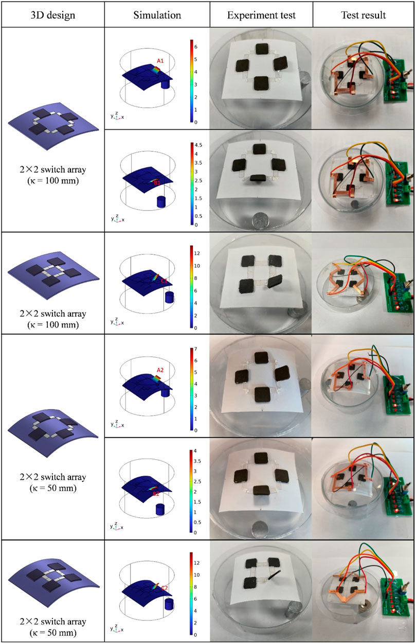
FIGURE 10. 2 × 2 hard-magnetic soft switch array under different curvatures and connection conditions for the curved surface applications.
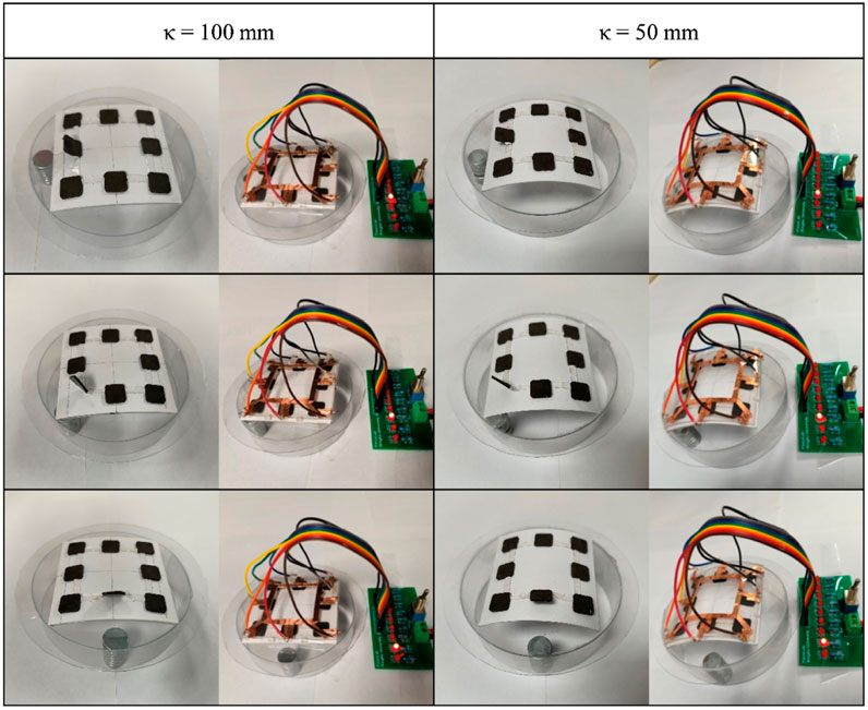
FIGURE 11. Experimental results of 3 × 3 hard-magnetic soft switch array for the curved surface applications.
4 Conclusion
In this work, we designed and developed a new switch array structure based on soft magnets which can be applied to the planar and curved surfaces environments. This work started with the preparation of hard-magnetic soft materials, characterization of their mechanical and magnetic properties, and testing of their related properties for the preparation of switches. By investigating the displacement responses of soft magnets under different directions of magnetic field, the displacement response relationship between remanent magnetization direction and magnetic field was determined, and verified through finite element calculation. In order to better achieve displacement response under magnetic field, we investigated the effects of different mass ratios of NdFeB/PDMS soft magnets and different connection methods. In the study of switch arrays, the planar 2 × 2 and 3 × 3 switch array structures were firstly designed and demonstrated through FEM simulation and experiments to show the displacement response under magnetic field, and the feasibility of the design was verified through LED lamp illumination experiments. Then, 2 × 2 and 3 × 3 switch array structures for the application on the curved surfaces were explored, and the working state of hard-magnetic soft switch array under different curvature conditions and connection conditions was investigated through device preparation and experimental testing, achieving precise control of a single switch and further application for programmable control. The design and preparation scheme of the hard-magnetic soft switch array proposed in this work is simple and easy to be implement. Its application feasibility and effectiveness on the planar and curved surface environments have also been verified. This work is of great significance for promoting the application and development of soft magnets in the fields of switch arrays, sensors and actuators in the future.
Data availability statement
The raw data supporting the conclusion of this article will be made available by the authors, without undue reservation.
Author contributions
PY: Data curation, Investigation, Methodology, Software, Writing–original draft. YG: Funding acquisition, Project administration, Writing–review and editing. XX: Formal Analysis, Resources, Writing–review and editing. BH: Conceptualization, Funding acquisition, Supervision, Writing–review and editing.
Funding
The author(s) declare that financial support was received for the research, authorship, and/or publication of this article. This work was supported by the Scientific Research Found of Zhejiang Provincial Education Department (Grant no. Y202351699) and Ningbo Major Research and Development Plan Project (Grant no. 2022Z210).
Conflict of interest
The authors declare that the research was conducted in the absence of any commercial or financial relationships that could be construed as a potential conflict of interest.
Publisher’s note
All claims expressed in this article are solely those of the authors and do not necessarily represent those of their affiliated organizations, or those of the publisher, the editors and the reviewers. Any product that may be evaluated in this article, or claim that may be made by its manufacturer, is not guaranteed or endorsed by the publisher.
References
Ahn, C. Y., Liang, X. D., and Cai, S. Q. (2019). Bioinspired design of light-powered crawling, squeezing, and jumping untethered soft robot. Adv. Mater. Technol. 4, 9. doi:10.1002/admt.201900185
Alapan, Y., Karacakol, A. C., Guzelhan, S. N., Isik, I., and Sitti, M. (2020). Reprogrammable shape morphing of magnetic soft machines. Sci. Adv. 6, eabc6414. doi:10.1126/sciadv.abc6414
Athas, J. C., Nguyen, C. P., Zarkett, B. C., Gargava, A., Nie, Z. H., and Raghavan, S. R. (2016). Enzyme-triggered folding of hydrogels: toward a mimic of the venus flytrap. Acs Appl. Mater. Interfaces 8, 19066–19074. doi:10.1021/acsami.6b05024
Cao, Q. L., Fan, Q., Chen, Q., Liu, C. T., Han, X. T., and Li, L. (2020). Recent advances in manipulation of micro- and nano-objects with magnetic fields at small scales. Mater. Horizons 7, 638–666. doi:10.1039/c9mh00714h
Chen, X. Z., Hoop, M., Mushtaq, F., Siringil, E., Hu, C. Z., Nelson, B. J., et al. (2017). Recent developments in magnetically driven micro- and nanorobots. Appl. Mater. Today 9, 37–48. doi:10.1016/j.apmt.2017.04.006
Cho, M. H., Lee, E. J., Son, M., Lee, J. H., Yoo, D., Kim, J. W., et al. (2012). A magnetic switch for the control of cell death signalling in in vitro and in vivo systems. Nat. Mater. 11, 1038–1043. doi:10.1038/nmat3430
da Cunha, M. P., Ambergen, S., Debije, M. G., Homburg, E., den Toonder, J. M. J., and Schenning, A. (2020a). A soft transporter robot fueled by light. Adv. Sci. 7, 7. doi:10.1002/advs.201902842
da Cunha, M. P., Debije, M. G., and Schenning, A. (2020b). Bioinspired light-driven soft robots based on liquid crystal polymers. Chem. Soc. Rev. 49, 6568–6578. doi:10.1039/d0cs00363h
Deng, H., Sattari, K., Xie, Y. C., Liao, P., Yan, Z., and Lin, J. (2020). Laser reprogramming magnetic anisotropy in soft composites for reconfigurable 3D shaping. Nat. Commun. 11, 6325. doi:10.1038/s41467-020-20229-6
Diller, E., and Sitti, M. (2014). Three-dimensional programmable assembly by untethered magnetic robotic micro-grippers. Adv. Funct. Mater. 24, 4397–4404. doi:10.1002/adfm.201400275
Garcia-Gonzalez, D., Ter-Yesayants, T., Moreno-Mateos, M. A., and Lopez-Donaire, M. L. (2023). Hard-magnetic phenomena enable autonomous self-healing elastomers. Compos. Part B Eng. 248, 110357. doi:10.1016/j.compositesb.2022.110357
Ghosh, D., Atkinson, A., Gibson, J., Subbaiahgari, H., Ming, W. H., Padgett, C., et al. (2023). 1,2,3-Triazoles: controlled switches in logic gate applications. Sensors 23, 7000. doi:10.3390/s23157000
Gu, G. Y., Zou, J., Zhao, R. K., Zhao, X. H., and Zhu, X. Y. (2018). Soft wall-climbing robots. Sci. Robotics 3, eaat2874. doi:10.1126/scirobotics.aat2874
Hu, W. Q., Lum, G. Z., Mastrangeli, M., and Sitti, M. (2018). Small-scale soft-bodied robot with multimodal locomotion. Nature 554, 81–85. doi:10.1038/nature25443
Jiang, S., Liu, J. P., Xiong, W. N., Yang, Z. X., Yin, L. T., Li, K., et al. (2022). A snakeskin-inspired, soft-hinge Kirigami metamaterial for self-adaptive conformal electronic armor. Adv. Mater. 34, e2204091. doi:10.1002/adma.202204091
Jiao, Z. D., Ji, C., Zou, J., Yang, H. Y., and Pan, M. (2019). Vacuum-powered soft pneumatic twisting actuators to empower new capabilities for soft robots. Adv. Mater. Technol. 4, 10. doi:10.1002/admt.201800429
Johnston, I. D., McCluskey, D. K., Tan, C. K. L., and Tracey, M. C. (2014). Mechanical characterization of bulk Sylgard 184 for microfluidics and microengineering. J. Micromechanics Microengineering 24, 035017. doi:10.1088/0960-1317/24/3/035017
Ju, Y. W., Hu, R., Xie, Y., Yao, J. P., Li, X. X., Lv, Y. L., et al. (2021). Reconfigurable magnetic soft robots with multimodal locomotion. Nano Energy 87, 106169. doi:10.1016/j.nanoen.2021.106169
Jurik, P., Sokol, M., Galajda, P., and Drutarovsky, M. (2023). Analysis and implementation of controlled semiconductor switch for ultra-wideband radar sensor applications. Sensors 23, 7392. doi:10.3390/s23177392
Kim, J., Chung, S. E., Choi, S. E., Lee, H., Kim, J., and Kwon, S. (2011). Programming magnetic anisotropy in polymeric microactuators. Nat. Mater. 10, 747–752. doi:10.1038/nmat3090
Kim, Y., Parada, G. A., Liu, S. D., and Zhao, X. H. (2019). Ferromagnetic soft continuum robots. Sci. Robotics 4, eaax7329. doi:10.1126/scirobotics.aax7329
Kim, Y., Yuk, H., Zhao, R. K., Chester, S. A., and Zhao, X. H. (2018). Printing ferromagnetic domains for untethered fast-transforming soft materials. Nature 558, 274–279. doi:10.1038/s41586-018-0185-0
Li, Y. L., and Wu, N. J. (2008). A low-cost CMOS programmable temperature switch. Sensors 8, 3150–3164. doi:10.3390/s8053150
Lin, Y. S., Huang, C. Y., Huang, C. T., Chang, J. F., Tien, N. W., and Chuang, Y. H. (2023). Design and analysis of complementary metal–oxide–semiconductor single-pole double-throw switches for 28 GHz 5G new radio. Electronics 12, 4156. doi:10.3390/electronics12194156
Lu, L., Sim, J., and Zhao, R. R. (2024). Mechanics of hard-magnetic soft materials: a review. Mech. Mater. 189, 104874. doi:10.1016/j.mechmat.2023.104874
Manamanchaiyaporn, L., Xu, T. T., and Wu, X. Y. (2020). Magnetic soft robot with the triangular head-tail morphology inspired by lateral undulation. Ieee-Asme Trans. Mechatronics 25, 2688–2699. doi:10.1109/tmech.2020.2988718
Mao, G. Y., Schiller, D., Danninger, D., Hailegnaw, B., Hartmann, F., Stockinger, T., et al. (2022). Ultrafast small-scale soft electromagnetic robots. Nat. Commun. 13, 4456. doi:10.1038/s41467-022-32123-4
Marcelli, R., Sardi, G. M., Proietti, E., Capoccia, G., Iannacci, J., Tagliapietra, G., et al. (2023). MEMS-switched triangular and U-shaped band-stop resonators for K-band operation. Sensors 23, 8339. doi:10.3390/s23198339
Martinez, R. V., Glavan, A. C., Keplinger, C., Oyetibo, A. I., and Whitesides, G. M. (2014). Soft actuators and robots that are resistant to mechanical damage. Adv. Funct. Mater. 24, 3003–3010. doi:10.1002/adfm.201303676
Moreno-Mateos, M. A., Danas, K., and Garcia-Gonzalez, D. (2023). Influence of magnetic boundary conditions on the quantitative modelling of magnetorheological elastomers. Mech. Mater. 184, 104742. doi:10.1016/j.mechmat.2023.104742
Moreno-Mateos, M. A., Hossain, M., Steinmann, P., and Garcia-Gonzalez, D. (2022). Hybrid magnetorheological elastomers enable versatile soft actuators. npj Comput. Mater. 8, 162. doi:10.1038/s41524-022-00844-1
Mosadegh, B., Polygerinos, P., Keplinger, C., Wennstedt, S., Shepherd, R. F., Gupta, U., et al. (2014). Pneumatic networks for soft robotics that actuate rapidly. Adv. Funct. Mater. 24, 2163–2170. doi:10.1002/adfm.201303288
Rehman, T., Faudzi, A. A. M., Dewi, D. E. O., and Ali, M. S. M. (2017). Design, characterization, and manufacturing of circular bellows pneumatic soft actuator. Int. J. Adv. Manuf. Technol. 93, 4295–4304. doi:10.1007/s00170-017-0891-z
Robertson, M. A., and Paik, J. (2017). New soft robots really suck: vacuum-powered systems empower diverse capabilities. Sci. Robotics 2, eaan6357. doi:10.1126/scirobotics.aan6357
Song, H., Lee, H., Lee, J., Choe, J. K., Lee, S., Yi, J. Y., et al. (2020). Reprogrammable ferromagnetic domains for reconfigurable soft magnetic actuators. Nano Lett. 20, 5185–5192. doi:10.1021/acs.nanolett.0c01418
Venkiteswaran, V. K., Samaniego, L. F. P., Sikorski, J., and Misra, S. (2019). Bio-inspired terrestrial motion of magnetic soft millirobots. Ieee Robotics Automation Lett. 4, 1753–1759. doi:10.1109/lra.2019.2898040
Weng, M. C., Duan, Y. M., Zhou, P. D., Huang, F., Zhang, W., and Chen, L. Z. (2020). Electric-fish-inspired actuator with integrated energy-storage function. Nano Energy 68, 104365. doi:10.1016/j.nanoen.2019.104365
Wu, S., Ze, Q. J., Zhang, R. D., Hu, N., Cheng, Y., Yang, F. Y., et al. (2019). Symmetry-breaking actuation mechanism for soft robotics and active metamaterials. Acs Appl. Mater. Interfaces 11, 41649–41658. doi:10.1021/acsami.9b13840
Xu, T. Q., Zhang, J. C., Salehizadeh, M., Onaizah, O., and Diller, E. (2019). Millimeter-scale flexible robots with programmable three-dimensional magnetization and motions. Sci. Robotics 4, eaav4494. doi:10.1126/scirobotics.aav4494
Ze, Q. J., Kuang, X., Wu, S., Wong, J., Montgomery, S. M., Zhang, R. D., et al. (2020). Magnetic shape memory polymers with integrated multifunctional shape manipulation. Adv. Mater. 32, e1906657. doi:10.1002/adma.201906657
Zhang, J. C., Onaizah, O., Middleton, K., You, L. D., and Diller, E. (2017). Reliable grasping of three-dimensional untethered mobile magnetic microgripper for autonomous pick-and-place. Ieee Robotics Automation Lett. 2, 835–840. doi:10.1109/lra.2017.2657879
Zhang, Y., and Liu, J. L. (2013). A new kind of low-inductance transformer type magnetic switch (TTMS) with coaxial cylindrical conductors. Rev. Sci. Instrum. 84, 023306. doi:10.1063/1.4791926
Keywords: hard-magnetic soft material, switch array, magnetic field, magnetic response, curved surface
Citation: Yang P, Guo Y, Xue X and Huang B (2024) A novel design of hard-magnetic soft switch array for planar and curved surface applications. Front. Mater. 11:1385988. doi: 10.3389/fmats.2024.1385988
Received: 14 February 2024; Accepted: 05 March 2024;
Published: 15 March 2024.
Edited by:
Daniel Garcia-Gonzalez, Universidad Carlos III de Madrid, SpainReviewed by:
Maria Luisa Lopez Donaire, Universidad Carlos III de Madrid de Madrid, SpainMiguel Angel Moreno-Mateos, Friedrich-Alexander-Universität Erlangen-Nürnberg, Germany
Copyright © 2024 Yang, Guo, Xue and Huang. This is an open-access article distributed under the terms of the Creative Commons Attribution License (CC BY). The use, distribution or reproduction in other forums is permitted, provided the original author(s) and the copyright owner(s) are credited and that the original publication in this journal is cited, in accordance with accepted academic practice. No use, distribution or reproduction is permitted which does not comply with these terms.
*Correspondence: Bin Huang, huangbin@nbu.edu.cn