Modeling for Design Optimization of Piston Crown Geometry Through Structural Strength and Lubrication Performance Correlation Analysis
 Prakash Chandra Mishra
 Santosh Kumar
- 1Green Engine Technology Center, School of Mechanical Engineering, KIIT University, Bhubaneswar, India
- 2Department of Mechanical Engineering, Veer Surendra Sai University of Technology, Burla, India
Piston subsystem is subjected to very complex but dynamic forces. Such forces include combustion gas force, inertial dynamics forces, lubricating action/damping forces, contact friction forces to name a few. Further, piston ring mounted in piston in addition to these forces experiences out ward springing action inside engine mounting due to inherent elasticity. To evaluate the strength of reciprocating piston, the simultaneous effect of all these forces should be considered, while simulating through finite element method. With effect of all these forces, the currently considered piston of Gray Cast Iron, aluminum alloy and Metal-Metric-Composite (Si-C) are given four different crown shapes for optimization of material and crown geometry for better strength. The rings mounted are considered to be coated with Nickasil. The combined numerical simulation for contact and finite element simulation of structural strength and their correlation suggest many important outcomes. Von-Misses stress is maximum in case of type-B Al-alloy crown, while it is minimum in case of type-C SiC metal matrix piston.
Introduction
Automotive being the largest consumer durable is currently irreplaceable by any other machine for mobility. Only renovation and up gradation is shut for improving performance and comfort (Holmberg et al., 2012). Engine being the vital component of automotive because of its inherent errant design principle achieve only <25% of it is input fuel energy as the output driving brake power (Akalin and Newaz et al., 2001a; Mishra et al., 2009; Morris et al., 2013; Mishra, 2015). Rest of this fuel energy is wasted either because of friction or emission or pumping loss (Smedley, 2004). Because of many connecting and contacting action within engine, parasitic loss due to friction is significant (Dursunkaya et al., 1994; Prata et al., 2000). Along with the friction forces due to ring-liner, skirt-liner, ring-ring groove land contact, the combustion gas force, inertia force, secondary dynamic forces of piston and pin, connecting rod force acts on the reciprocating piston subsystem of a running engine (Akalin and Newaz et al., 2001a; Mishra et al., 2008; Chong et al., 2012; Shahmohamadi et al., 2013). For the life assessment and durability study of the piston it is necessary to count the effects of such forces on piston made up of Gray Cast Iron, Al-alloy, and Si-C (Metal matrix composite) that upto with variable crown geometry.
The forces due to wet contact friction in the case of skirt-liner and ring-liner contact is cyclic and with rapid action (Park and Lee, 2014; Usman and Park, 2016). The contact conjunction of relatively moving piston subsystem includes ring-liner, skirt-liner and ring-ring groove (top and bottom) contact. Such relatively moving piston surfaces are subjected to faster sliding action and simultaneous axial fluttering (Karamangil et al., 2004; Usman et al., 2015). In all cases, the flow of lubricant oil is ensured through appropriate lubrication mechanism to retain acceptable engine life (Abou-Ziyan, 2004). Ring-liner conjunction because of influence of variable gas pressure in ring back executes sealing and relaxing action with increase and decrease value of chamber pressure (Bolander et al., 2005). These results in decrease or increase in conjunction gap there by initiating the presence of lubrication regime transition (Ma et al., 1995, 1997). Without gas pressure in the mid stroke, the film thickness sometimes goes as high as 5 μm leading to hydrodynamic regime (Froelund et al., 2001). But at higher pressure zone of engine cycle (300–400° cycle), where the gas pressure is dominant, and the film thickness reduced to as low as the roughness height of the surface, but still there is no asperity interaction that leads to mixed nature of transient regime of lubrication (Rahmani et al., 2012). In such case the effect of roughness height is felt in flow of lubricant (Tripp and Greenwood, 1970; Qasim et al., 2012; Mishra, 2013).
At the vicinity of top dead center (355–365°) the momentary cessation of piston because of reversal, lead to negligible sliding share of such contact. If there was not any metal-to-metal contact wear, it would be due to hydrodynamic action out of film squeeze effect (Mishra et al., 2008). Film retained is much lower than the asperity height and guaranteed boundary friction (Akalin and Newaz et al., 2001b; Bolander et al., 2005). To avoid such possibility of rapid wear, micro conjunctions are created intentionally by engraving the ring or liner surface by creating small pools of lubricant (Ryk et al., 2002). Benajes et al. (2016) studied the effect of bowl geometry on combustion losses at different load.
Further, piston body due to its eccentric positioning and simultaneous primary and secondary motion tilt toward and away from the liner at top and bottom end, respectively. Approach toward liner reduce the film thickness and promotes the skirt and down crown position to operate in mixed lubrication regime (Mishra et al., 2015). The eccentric positioning of piston and the lateral tilt angle leads to thrust and anti-thrust situation and friction loss further at the top and bottom of skirt. Cyclic variation of friction and repetitive nature of active and reactive forces in piston subsystem decides the life of piston. Considering all these forces, to analyze the strength of piston of variable crown geometry is the objective of this research work.
Theory of the Model
It is necessary to understand the subsystem dynamics, contact condition, asperity interaction and finite element analysis to the greater detail to model piston subsystem. Figure 1 shows the free body diagram of the piston body and ring, respectively. It shows there is combined effect of primary force like, gas pressure force, inertia force and secondary force like, friction, force on connecting rod, and force of piston mass acting eccentric to vertical axis. There are two moments acting, one around wrist pin and other about center of gravity of piston. If these are like or unlike depends on the magnitude of variable forces.
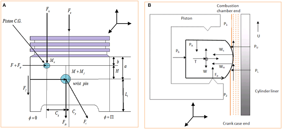
Figure 1. (A) Free body diagram of piston subsystem (Mishra, 2015). (B) Free body diagram of coated piston ring in reciprocating piston (Mishra et al., 2015).
Further, the forces developing on the ring include, the gas pressure forces from three sides and of different magnitude. The force (a) responsible for conforming the ring in groove land, while (b) type gas force or ring tension help in sealing the ring and liner gap for optimum blow by conditions. Type (d) force is frictional force or support reaction force, developed due to rapid shear of lubricant.
Further, simultaneous sealing and sliding also leaves the chance of ring or liner wear in such faster moving reciprocating contact. A good ring liner pair should have the higher degree of conformance and at the same time better resistance against wear. To achieve longer order component life, geometry modification in terms of parabolic profile provision for piston body as well as ring face is considered. Along with such macro modification, micro surface evolution like ring texturing and liner is hatching to intentionally create roughing surface helps to achieve better performance. Also, coating of ring surface for strength is found helpful to minimize wear.
Force Configuration of Piston and Ring
Piston being a rigid system subjected to complex, dynamic yet variable forces during an engine cycle (Mishra, 2015). The free body diagram of a dynamic piston is given in Figure 1.
Here the direction of reciprocation is along x-axis, unwrapped cylinder circumference is taken along y-axis and the film thickness is taken along z-axis. The force “Fg” presents the cyclic gas pressure force, which is more dominant in (300–400)° crank location in the engine cycle (Mishra et al., 2015). This force is not only responsible for piston primary motion, but also helps in achieving compression ring sealing due to its radial action on the back of the ring (Ma et al., 1995; Mishra, 2013). Further, Fgs and Fps acted as shown are the inertia force caused due to primary reciprocating motion of the pin and the piston assembly, respectively. These are product of respective mass and the primary reciprocating acceleration and given in Equations (1, 2).
Piston is subjected to secondary motion due to its eccentric position with respect to bore axis. For which, mpin and mpis are mass of pin and mass of piston, respectively. The secondary forces and secondary moments are given in Equations (3–5), respectively.
The ξt and ξb in the above equations are secondary accelerations, which are obtained by differentiating the eccentric positioning et and eb for two times with respect to time. The et and eb are the top and the bottom eccentricities given in Equations (6, 7), respectively (Liu et al., 1998).
Further to this analysis, the forces and moment due to hydrodynamic action and are F, Ff, M, and Mf, respectively (Liu et al., 1998). These forces are presented in figure in Equations (8–11). As stated earlier, sliding is occurring in “x” direction, while “y” is the direction of circumference (side leakage) and “z” is the direction along film thickness.
“F” and “M” are due to lubricant damping action, while “Ff” and “Mf” are due to combined fluid and asperity shear induced friction, respectively. Further, the film pressure ph is the hydrodynamic/elastohydrodynamic pressure due to lubricant entrainment to the piston-liner or ring-liner conjunction. The hydrodynamic/EHL pressure is estimated in this analysis through numerical solution of the two dimensional Reynolds equation stated in Equation (12) (Liu et al., 1998; Mishra et al., 2009).
In Equation (12), the total film thickness is hT, which is obtained due to finite integration from the negative to the positive infinity of the product of probability density function f(ψ) and the sum of nominal film thickness (h) and composite surface roughness (ψ).
Further, the probability density function f(ψ) is of composite roughness (ψ), which is the sum of roughness of piston ring and liner or skirt-liner. The Figure 3C presents the complied rough surface of ring-liner or skirt liner conjunction. Further Figure 3D shows the combustion pressure, first and second inter ring pressure respectively. Assuming (ψ) with the Gaussian distribution. hT is expressed in Equation (13). The erf () is the Gaussian error function or complementary error function (Usman and Park, 2016), considered to estimate total film thickness.
Where,
In Equation (13), (h) is the film thickness in between the rough cylinder liner and mounted ring. Such zoomed interface is presented in Figure 2. The unsymmetrical composition of film thickness includes axial parabolic variation (hx), radial bore distortion variation (hy). On top of it, ψ1 and ψ2 are microscopic surface roughness. With combined elastic deformation, thermal expansion and elevated temperature, the ring end gap reduces and conformed better (Usman and Park, 2016).
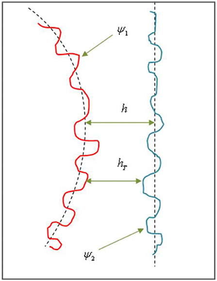
Figure 2. One dimensional rough surfaces compilation of ring-liner/skirt-liner conjunction (Zoomed to sense peak and valley).
Mathematically, the film thickness between two roughness surface is given as Equation (14).
The film thickness for skirt-liner conjunction is quantified and presented in Equation (15)
Where, “C” is the nominal clearance/Minimum gap between skirt-liner profile and Sk(y) is the skirt profile. The component (a) of the Equation (15) is due top eccentric positioning and component (b) is due to bottom eccentric positioning. The sum of nominal film, tilting gap and the skirt profile (Liu et al., 1998) leads to the skirt-liner conjunction film thickness. Further, the ring-liner film is quantified as per Equation (16). The h0 is the minimum gap between flexible rings after conformed to bore surface (Ma et al., 1995, 1997). The shape function is taken as single point minima type parabolic profile (Mishra et al., 2009). The Δi,j is the ring global deformation due to inward and out ward springing action resulting due to combined action of various forces given in Figure 1B. Similarly, δi,j is the local elastic deformation, which is not considered in this case because of it is small order [10−8 m or 10 nm] (Mishra et al., 2009).
Thus, such case sensitive film thickness is reduced to
In case of piston subsystem components, the contact pressure/friction is due to viscous action initiated due to hydrodynamic/elastohydrodynamic. At the vicinity of dead center, pressure/friction due to asperity contact is added. At any instant of time of engine operation, the balance of applied force acting on the ring-bore/skirt-liner conjunction and the corresponding reaction forces is obtained through Equation (17).
Where, Fh is the force due to hydrodynamic/mixed lubricating action in ring-liner or skirt-liner conjunction (Ma et al., 1995, 1997; Mishra, 2015). It obtained by areal/double integration of film pressure as presented in Equation (18). Further to this explanation, the asperity contact force Wa initiated due to boundary friction, most likely occur in the vicinity of the dead centers [TDC/BDC] due to momentary cessation of lubricant entraining motion (Hu et al., 2011; Chong et al., 2012).
In the Equation (19) β′ is the asperity radius, N′ is the number of asperity per unit real contact area, E′ is the composite elastic modulus.
The total friction loss (Ft = Fv + Fb). Hence total friction can be represented in Equation (20) is the sum of the viscous friction and boundary friction. The viscous friction is the areal integral of fluid shear, while the boundary friction is the function of limiting Eyring shear stress, asperity tip radius, asperity density per unit real area of contact and the roughness function F2.
With limiting shear stress (τ0) value of 2.0 MPa and with coefficient of boundary strength (ς = 0.17) of harder surface asperity in encounter with softer one. Further, F2 is the function related to the probability distribution of asperity height. It is the governing parameter for boundary friction estimation (Eyring, 1936). The F2 with surface roughness of Gaussian distributed asperities (Abou-Ziyan, 2004) is expressed in Equation (21).
Here, F2 is one important parameter for boundary friction estimation.
Ring-Bore Conformability
As discussed earlier, film between ring-liner/skirt-liner is important parameter that controls contact forces of piston subsystem (Shahmohamadi et al., 2013). Further, the static gap between ring-bore is highly dependable on bore out-of-roundness. Hence, it is essential to know the bore radial difference, which is the difference between the measured liner inner radius and the nominal bore radius (ΔR(θc) = Rm−R0) along the 180 nodes considered in the circumferential direction. The measurement is taken through a co-ordinate measuring machine for 1,000 circumferential points and FFT interpolated to 180 nodes of 180 × 16 grids. The circumferentially variable minimum film is the net of bore radial difference and the conformability factor ξn(θc) and is presented in Equation (22) as per (Ma et al., 1995, 1997).
Where,
And,
Further,
And,
Here, Pgf(θc) is the gas pressure from the front of the ring, Pgb is the gas pressure from the back of the ring (Mishra et al., 2009). The front gas pressure is the function of leading, trailing end gas pressure, the profile position, cavitation position and the ring face width. The leading edge pressure (Pl) is the combustion chamber pressure during piston upstroke motion (compression/exhaust) and crank case pressure during down ward stroke (power/suction). Similarly, for piston up ward stroke the trailing edge pressure (Pt) is the crank case pressure and during downward stroke, it is combustion pressure. In Equation (24), the elastic force is the function of ring elastic pressure and face width (Fe = Pgbb) (Hill and Newman, 1984).
The composite roughness of bore-ring, skirt-liner along with bore-out-of-roundness controls the lubricating effect of the oil. Figure 3a presents the measuring of the free ring profile and fitted ring profile. The measurement is carried out using a coordinate measuring machine (CMM), which uses a roller type stylus to sense the 3-D location of discrete points of the ring outer and inner edge, while free and fitted inside the bore. The bore diameter is also measured using spherical stylus. The conformed ring-liner gap is calculated by taking the difference of bore radius and fitted ring outer radius.
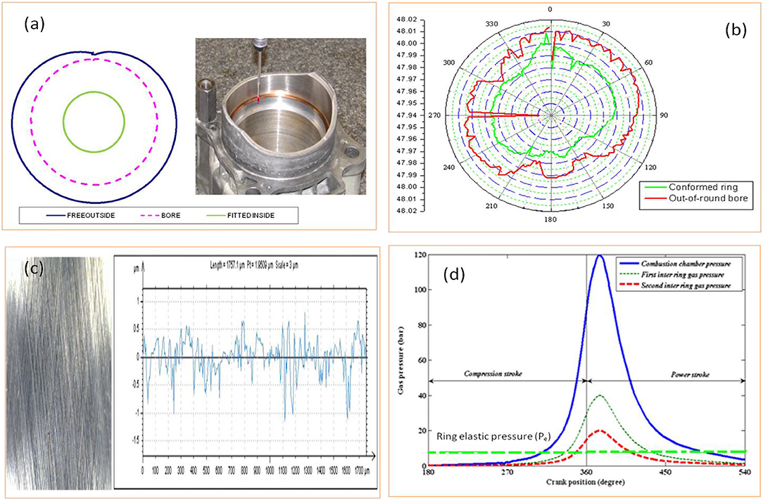
Figure 3. (a) Measurement of bore and ring out-of-roundness using CMM (Mishra, 2008). (b) polar plot of bore and ring radius measurement for 180 circumferential nodes. (c) Rough surfaces compilation of ring-liner/skirt-liner conjunction and (d) Cyclic variation of combustion chamber/inter ring/ring elastic pressure.
Lubricant Rheology
The EHL/hydrodynamic film pressure is greatly influenced by bulk rheological properties of lubricating oil. Such properties includes viscosity, density, pressure, and temperature and their inter relationship (Vogel, 1921). In case of contact conjunctions like skirt-liner, ring-liner, it is required to estimate the dynamic viscosity at each crank angle for whole engine cycle (Houpert, 1985). For this, the viscosity-temperature-pressure inter-relationship and density-pressure-temperature relationship must be discussed in detail.
Viscosity Response to Temperature and Pressure Variation
The influence of temperature and pressure variation on viscosity is given in Equation (26).
where: Θ = θ + 273 and Θ0 = θ0 + 273, and:
Where Z and S0 are characteristics specific to particular lubricants
Where, α0 and β0 are piezo viscous and thermo viscous coefficients (Dowson and Higginson, 1959; Cross, 1965; Larsson et al., 2000).
Density Response to Temperature and Pressure Variation
Though the hydrodynamic/EHL pressure generated is not strong enough to alter density (ρ0 = 1,800 kg/m3) we wish to test the same at highest possible pressure and temperature in ring-liner and skirt-liner conjunction.
Further to this analysis, in this faster moving reciprocating contact, the viscosity other than temperature and pressure is also highly dependent on the oil shearing rate (Dowson and Higginson, 1959; Larsson et al., 2000). It is required to calculate the shear rate as per given figure. In such faster moving reciprocating contact, the second Newtonian viscosity is more important than first one during high shear rate in warm up period, other than close vicinity of dead centers (Usman and Park, 2016). In such case, the shear dependent viscosity is given as in Equation (28).
Where β and k are oil-dependent fitting parameters and .
The viscosity ratio considering primary and secondary shear is presented in equation (29a)
Table 1 shows the viscosity dependency parameters in piston-liner contacts. The % variation of same in different crank angle is presented.
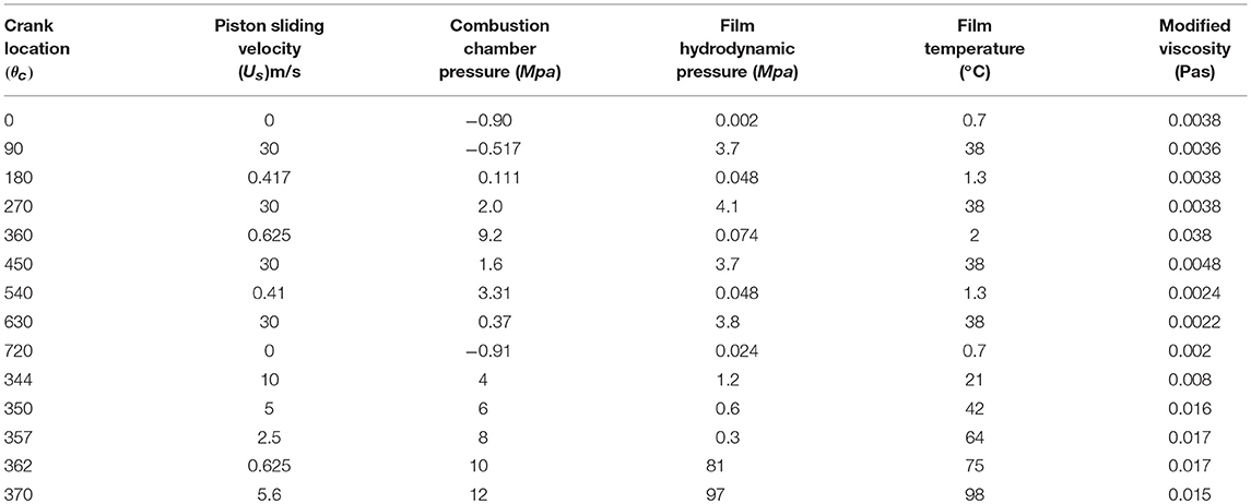
Table 1. Viscosity dependency parameters in piston-liner contacts (At selected crank location).
Boundary Conditions
The piston subsystem problem solution requires consideration of moving boundaries. Here, for pressure and temperature, the system extreme position operates in large difference of temperature and pressure. In one side of the piston subsystem, there is combustion chamber with cyclic maximum temperature and pressure, which goes upto 450°C and 12 Mpa, respectively. On the other side, crank case zone pressure and temperature is taken as lower end boundary. The boundary conditions of the current analysis are stated as:
• Because of frequent change in direction of sliding, the inlet direction changes due to frequent reversal of leading edge and trailing edge in a frequent interval (Mishra et al., 2009).
• The flow of lubricant is considered along x-direction and the inlet of the oil flow is taken as fully flooded (Morris et al., 2013).
• The pressure boundary conditions depend on pressure at top and bottom face of the ring, which depends on ring residing position (Mishra et al., 2009; Morris et al., 2013).
• The ring resides on top groove land, while piston is set to downward motion (suction/power stroke) as shown in Figure 4A. It resides on the bottom groove land when the piston in motion to upward direction (compression/exhaust), Figure 4B. Table 2 represents detail of forces noted in Figures 3a,b.
• The upper side pressure is variable combustion pressure, while the lower end pressure is crank case/atmospheric pressure.
• Because of more dominant effect of other force in the entire piston assembly, contribution of cavitating action is currently ignored.
• The contact exit boundary conditions are assumed to be those of Swift–Stieber, thus: ph(xc, y) = pc and (∂ph/∂x)x = xc = 0. These boundary conditions determine the position of lubricant film rupture (Rahmani et al., 2012).
• Piston is considered to be pinned in the gudgeon pin bore using gudgeon pin.
• There are four different crown geometry considered for FEM analysis. The geometries of the same are created using a CAD tool. The cups are created by removing the material and the doom is created by shaving the crown.
• Piston top ring is considered to be coated with Nickacil (Harshavardhan and Mallikarjuna, 2015).
• Other contact friction, such as that due to groove land-ring contact, gudgeon piston bore contact is considered negligible compared to ring-liner, skirt-liner contact friction.

Figure 4. Ring-liner force configuration during reciprocation. (A) Piston down ward motion (Suction/Power). (B) Piston upward motion (Compression/Exhaust).
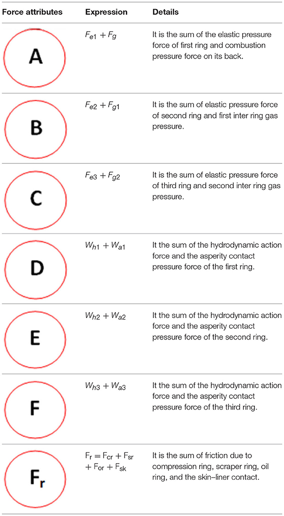
Table 2. Force description for piston up/down ward motion.
Table 2 presents the force description for piston up/down ward motion. All the forces acting on the piston subsystem is noted through some notations.
Over All Force and Moment Balance for Fem Analysis
This analysis leads to computation of F, Ff, M, and Mf. The equation of equilibrium for the force and moments are given in Equations (29–31) as per (Liu et al., 1998).
After elimination of Fcr from Equations (30–32)
Where,
The force configuration stated in Figure 1 thus computed and used as force input in the FEM formulation. Table 2 shows the description of the force for piston in up/down ward motion.
Finite Element Formulation of Piston and Liner
The finite element model developed in this paper is to model the piston made up of Gray CI, Al-alloy and SI-C with four variable crowns and compression ring with nickacil coating. Usually a commercially available FE software package (ANSYS) is used as simulation tool. All the components are modeled considering each as three dimensional beam elements. The simulation method consists of both pre-processing and post-processing steps. The preprocessing steps include creation of geometry in CAD software and importing it to the ANSYS. Later on the material properties are defined and meshing of the individual components is done using automated software provision. The piston is pinned at the gudgeon end, while the ring is assumed to be supported at the bottom land during upward motion and on the top land during the downward motion.
Result Analysis
To inter link performance and strength, it is highly required to correlate the piston ring, liner, skirt geometry with all possible applied forces. The input parameter used is of wide range and is presented in Table 3. In this analysis, there are two geometry modification considered for piston i.e., piston skirt axial profile and piston variable crown design. Figure 5A presents all four different skirt profile of parabolic shape, which is useful in having single point minima. Four profiles with four different profile height (0–20 μm) are considered for piston skirt. The solution to this model is divided into two sub routine. First a minimum gap is considered based on experimentally available variable gap as shown in Figure 3b from conformability analysis. Later, the hydrodynamic/EHL pressure is computed. Though suitable load convergence criteria, film relaxation is carried out to exact the film.
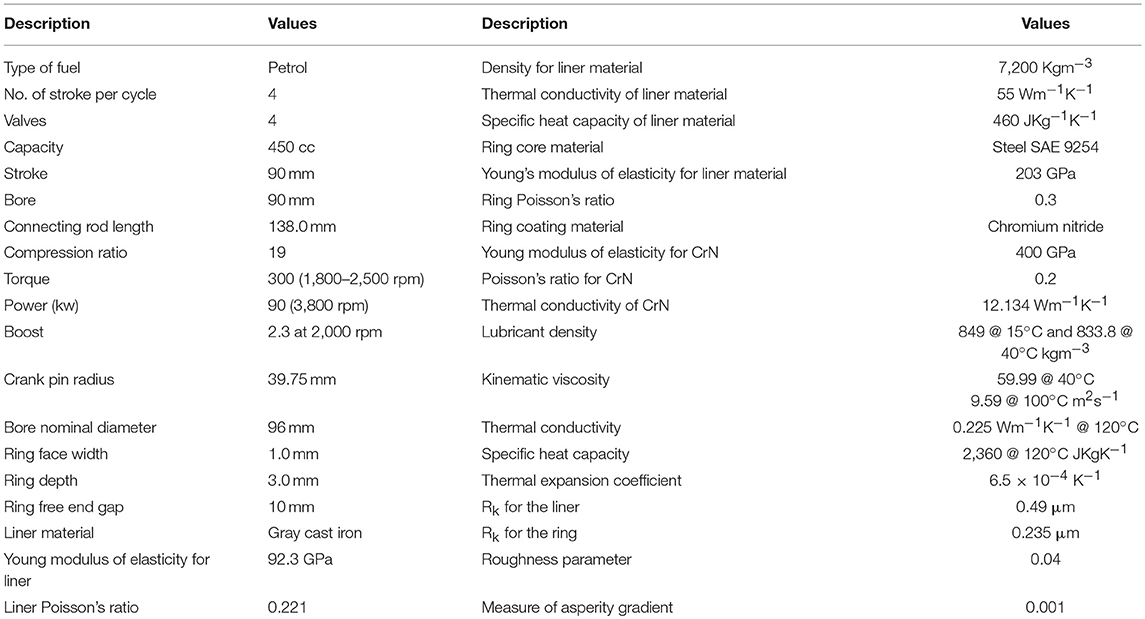
Table 3. Details of Input parameters (Mishra, 2015).
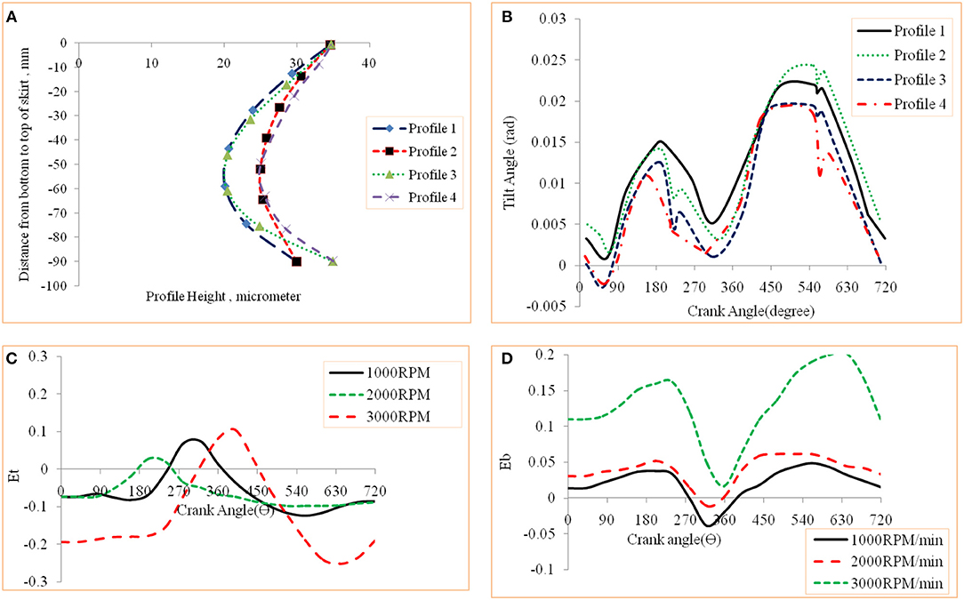
Figure 5. (A) Variation of profile geometry. (B) Cyclic variation of tilt angle for various profiles. (C) Cyclic variation of top eccentricity. (D) Cyclic variation of bottom eccentricity.
Further, all contacting and primary as well as secondary forces are evaluated and used as forces/load inputs to the piston of different crown geometry. Because of multiple forces acting in multiple plane of piston, there happens a lateral tilting. The Figure 5B presents the cyclic variation piston tilt in an engine cycle. The maximum tilt of 0.022 degree occurs at 540° crank location. Figures 5C,D shows the variation of Et and Eb at different rpm (1,000, 2,000, 3,000).
The Et/Eb increases with increasing rpm. Figures 6A,B shows the cyclic variation of friction force and friction power loss for the piston skirt in comparison to piston subsystem. Both these parameters are significant in 180–540° crank location. The highest value of skirt-liner friction is 18% of total friction force. Again the friction power is significant in power stroke and is near to 43% of total piston assembly friction wasted during power stroke. Further, 25% of total friction is skirt friction. Figures 6C,D shows the cyclic variation of Et and Eb for variable skirt profile. Profile with higher offset has greater Et/Eb. Eb is more compared to Et, reason being the skirt length (bottom) is more than that in top. The Figure 6E presents the cyclic variation piston tilt for different profile of piston.
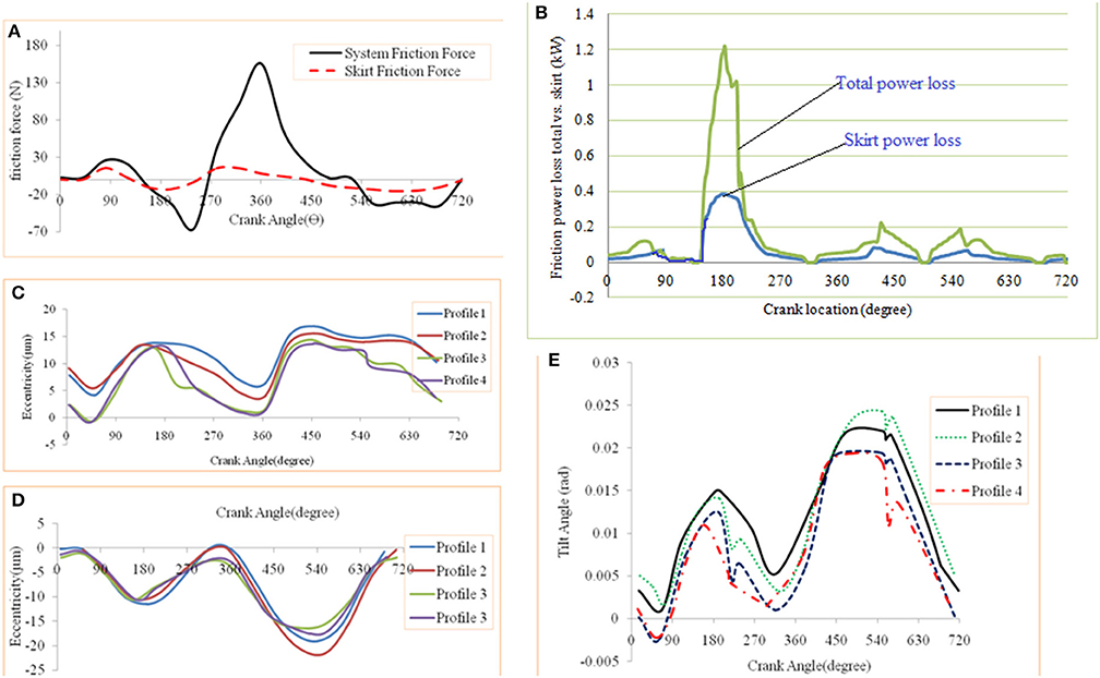
Figure 6. (A) Skirt vs. system friction force. (B) Skirt vs. system friction power. (C) Cyclic variation of top eccentricity. (D) Cyclic variation of bottom eccentricity. (E) tilt angle variation due to geometric profile change.
Friction force due to contact controls component life. A close monitoring to its cause and quantity can help modifying component for enhanced life against frictional losses. Figures 7A–D presents the cyclic variation of friction force of ring1 (compression ring), ring2 (scraper ring), ring3 (oil control ring) and the total piston subsystem friction. Among rings, the ring1 friction force is 65N maximum in power stroke. It is because of heavy back pressure during that period which leads to more damping action pressure. Ring2 has 83% less friction force than ring1 while ring3 has 75% less than that of ring1. The ring1 has 65% of the total piston subsystem friction. Further to such analysis, the cyclic variation of friction increases with increase in rpm. Such friction force difference is distinguished toward dead centers. It may be due to addition of asperity contact friction. Piston subsystem friction is required to estimate powerloss due to friction and is the product of friction force and the sliding velocity.
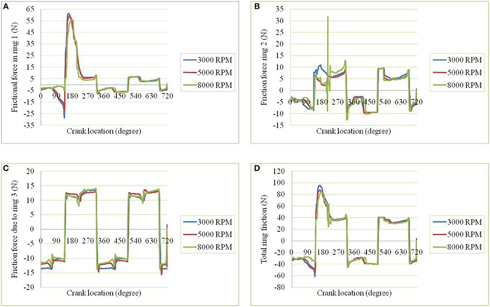
Figure 7. (A) Friction force of compression ring. (B) Friction force of scraper ring. (C) Friction force of oil ring. (D) Total friction of piston subsystem.
Energy loss due to friction can be calculated as Eloss = tcycle*Pavg, where Pavg is the average power loss in an engine cycle and tcycle is the total number of cycle. Power loss (P = FT·u) is the product of instantaneous velocity and the friction force (Mishra et al., 2009).
Figures 8A–D presents the cyclic variation of powerloss at the three different rpm (3000, 5000, 8000) for the ring1, ring2, ring3 and total friction, respectively. Maximum friction power in ring1 is 0.34, 0.68, 1.25 kW for 3,000, 5,000, 8,000 rpm, respectively. Similarly, for ring2 it is 0.04, 0.12, 0.34 kW. Similarly, for the third ring it is 0.2, 0.32, and 0.5 kW. The total friction power is 1.8, 1.1 and 0.56 kW, respectively. To summarize friction power, ring1 has highest friction powerloss among rings, which is 60% of total friction loss. While, friction powerloss is second highest in ring2, which is about 16% of total subsystem friction. Finally ring3 loses 14% of total friction.

Figure 8. Cyclic variation of friction power with variable rpm (A) Friction power of compression ring. (B) Friction power of scraper ring. (C) Friction power of oil ring. (D) Total friction power of piston subsystem.
During reciprocating motion of the piston, the rings changing the seating position from top to bottom groove land. Such cyclic loading in high temperature environment leads to thermo-mechanical stress and fatigue failure. In order to prevent such failure, thermal barrier coating like Nickasil of several micrometer are PVD coated. It is necessary to know strength of such coating in such highly non-linearly dynamic environment.
Further, it is almost next to impossible to experimentally know such strength. Hence, it is recommended to carry out finite element simulation of coated ring using FEM tool like ANSYS. Figure 9A shows the force configuration of coated top ring. The element type thus defined is taken from structural mass and SOLID-TET 4 NODE 285 as shown in Figure 9C. The next step in this method is to convert the whole ring into number of elements and these elements are connected through nodes. The elements thus chosen are tetrahedral solid elements. Next step is to loading and setting boundary conditions. Finally, solution and post-processing to view the results. Because of couple produced due to non-concurrent and out-of-plane forces, there is axial twist upto 3° as shown in Figure 9B. The main post-processing result shows the highlighted von-Misses fringe in coating and substrate interface. The Figure 9D shows the highlighted von Misses stress fringe in coating and substrate interface.
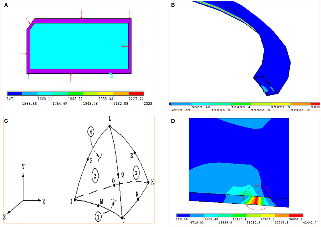
Figure 9. (A) Loading condition on coated ring. (B) Ring twist due to action of applied forces. (C) FEM element type. (D) Highlighted von Misses stress fringe in coating and substrate interface.
Taking all these forces, stress, deflection pattern into consideration, we decided to proceed further to the strength analysis of pistons with four different crown design. Each design again considered to be made of three different materials, such as Al-alloy, Gray cast iron and SiC metal matrix composite. Figures 10A–D presents the solid model four different crown design designated as type-A, type-B, type-C, and type-D, respectively. In type-A piston, the crown is considered to be conical with 0.5 cm crown height. While, type-B crown with a small pool to facilitate with more clearance volume compared with flat crowned piston. Further, type-C piston crown considered a small pool on middle and large flat surface on the edge. Finally, type-D piston crown with two cup on same side as shown in Figure 10D. All these pistons are modeled with ring groove and groove pin bore before imported to ANSYS (Harshavardhan and Mallikarjuna, 2015).
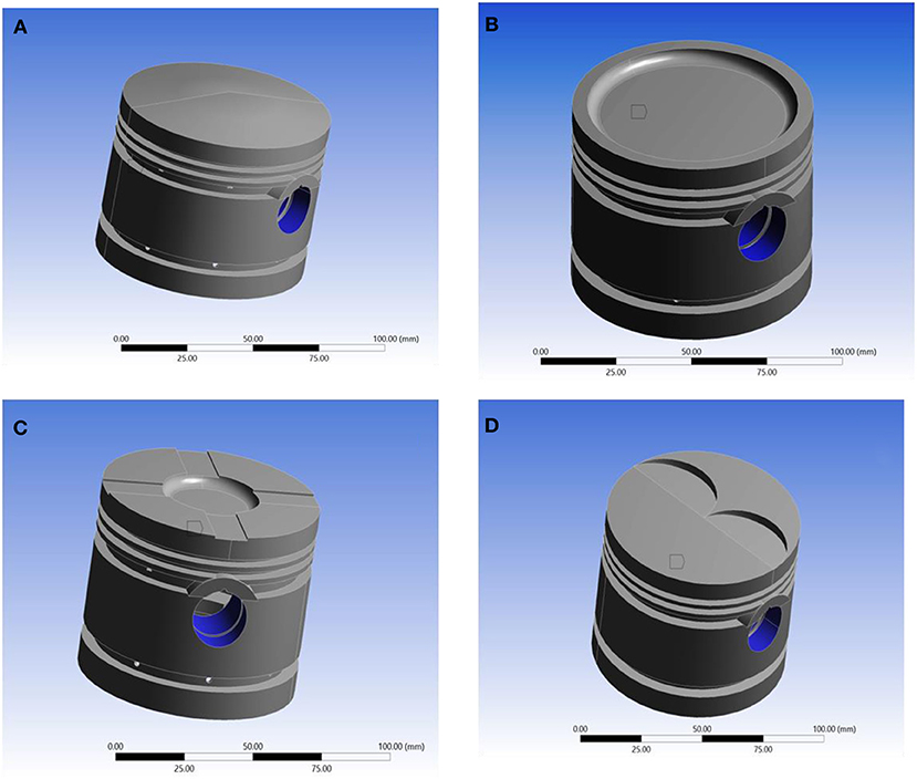
Figure 10. (A) Solid model of type-A piston. (B) Solid model of type-B piston. (C) Solid model of type-C piston. (D) Solid model of type-D piston.
The next to FEM analysis is to convert the solid structure to mesh model. Within ANSYS, there is a provision of automatic mesh element selection protocol that allows appropriate number of element, node, faces, minimum edge size and element type selection. Figures 11A–D shows the mesh model of four different crown designs [38–39]. In each case, the tetrahedral type element auto selected. Table 4 shows the mesh detail of different design. Further to this analysis, the load and boundary conditions is set as per earlier output forces.
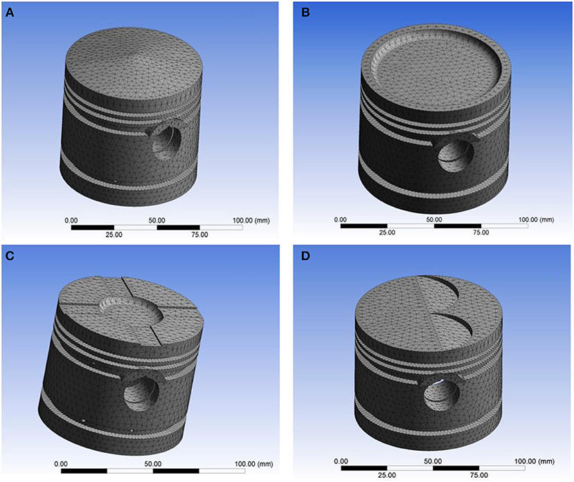
Figure 11. (A) Mesh model of type-A piston. (B) Mesh model of type-B piston. (C) Mesh model of type-C piston. (D) Mesh model of type-D piston.
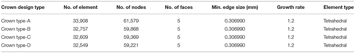
Table 4. Meshing detail for different design.
In Tables 5–7, the mesh convergence for key performance parameter, such as von-Misses and total deformation is carried out. With such convergence test, element size is chosen. The Figure 12 shows the total elastic deformation of type-A piston. The highest elastic deformation with stated load and boundary condition happens in case of Si-C metal matrix composite. Least deformation being in case of Gray Cast Iron. But some other mechanical/thermal properties make Gray cast iron less suitable in comparison to Al-alloy. Further, von-Misses criteria is most important criteria to understand the failure mode approach which is based on distortion energy/shear strain energy (Dobrucal, 2016).
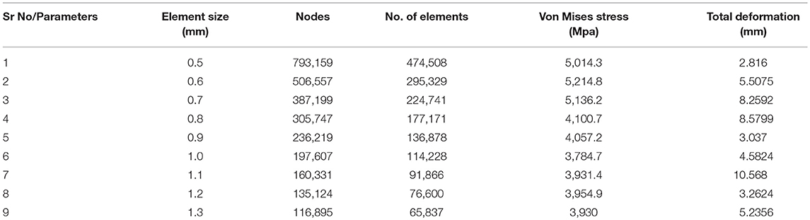
Table 5. Mesh convergence response to key parameters (for Al alloy).
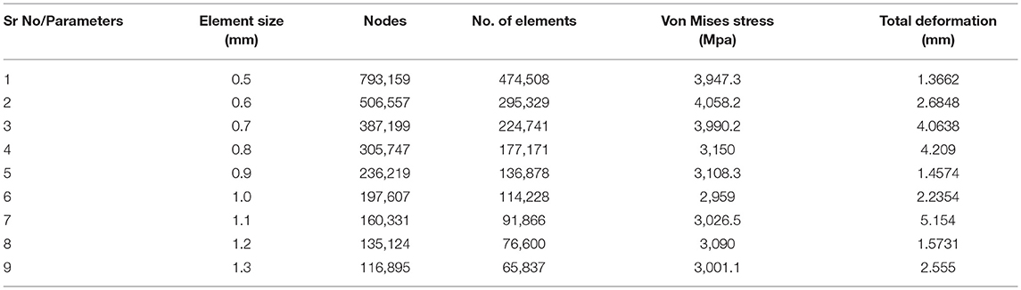
Table 6. Mesh convergence response to key parameters (for Gray cast iron).
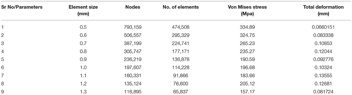
Table 7. Mesh convergence response to key parameters (for SiC).
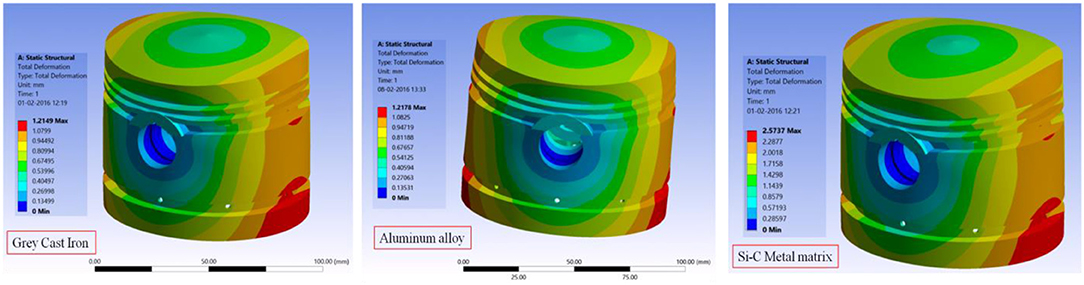
Figure 12. Total deformation for different materials.
Figure 13 shows the von-Misses stress for Gray-CI, Al-alloy, and SiC metal matrix. With stated load and boundary conditions, Al-alloy has highest ever von-Misses stress among the chosen materials. That is the reason it is most widely used material for piston manufacturing.
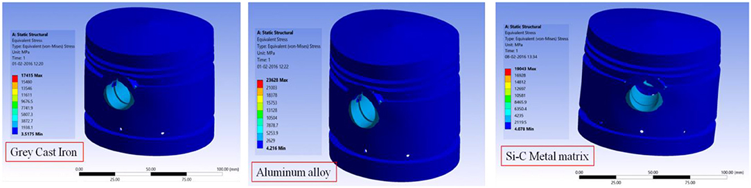
Figure 13. Total von-Misses for different materials.
Similarly, Figures 14–16 shows the comparison of maximum principal stress, minimum principal stress, maximum shear stress for different specified material. In addition to this, Figures 17A–F shows meshing, force location, coating-substrate interface stress fringe, out-of-plane twisting and volume strain in up stroke and down stroke motion.
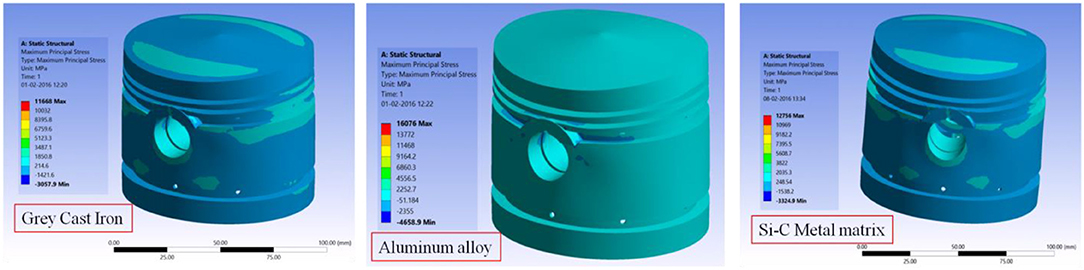
Figure 14. Maximum Principal Stress for different materials.
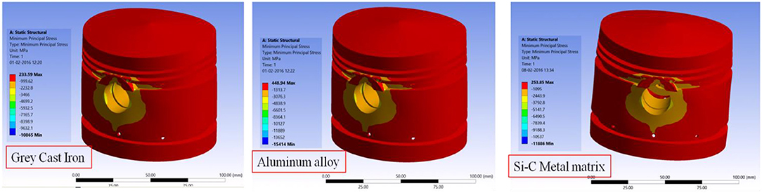
Figure 15. Minimum Principal Stress for different materials.
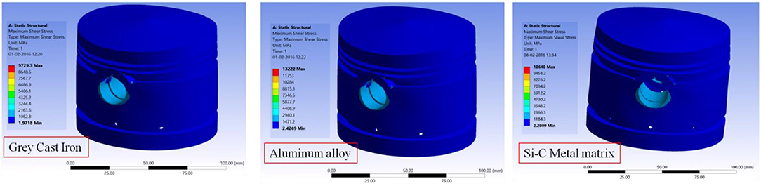
Figure 16. Maximum Shear stress for different piston materials.
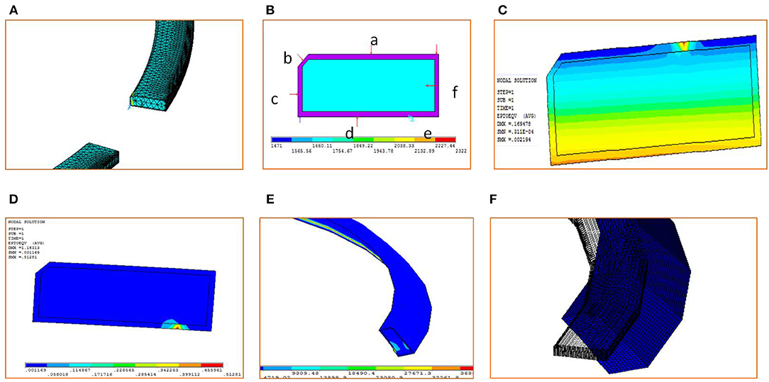
Figure 17. FEM output results for coated ring (A) Meshing of ring. (B) Free body diagram of ring. (C) Interface strain fringe during down stroke motion. (D) Interface stree fringe during upstroke motion. (E) Out-of-plane twisting of ring. (F) Ring volumetric strain due to up/down strokes.
Table 8 presents the summary of results of the combined structural strength and lubrication performance analysis. The details of the strength parameters and their maximum and minimum values are marked in the table. The maximum values are shaded in red, while the minimum mark is shaded in red.
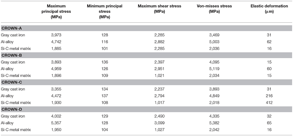
Table 8. Summary of results.
Conclusion
For the sustainable engine technology development, it is necessary to correlate the lubrication parameters with the strength of the piston. There is great level of complexity in operational principle and in other hand the life expectancy, which are carefully formulated to address specific phenomena and its overall contribution to main objective of strength analysis. Following conclusions are drawn.
• Maximum principal stress is maximum in case of Al-alloy piston of type-D crown design, while it is minimum in case of type-A crown make out of SiC metal matrix composite.
• Minimum principal stress is found to be maximum in type-C crowned piston manufactured from Al-alloy, while the minimum principal stress is marked in case of SiC metal matrix composite of A-type crown design.
• Maximum shear stress is another parameter which is vital to evaluate strength based life. Type-D crown of Al-alloy has maximum shear strength, while B-type crown of SiC metal matrix composite has minimum shear strength.
• Von-Misses stress is maximum in case of type-D Al-alloy crown (5,382 MPa), while that of stress of type-B Al-alloy crown is 5,119 MPa. The minimum is in case of type-C SiC metal matrix.
• Finally, type-B GCI and SiC metal matrix make pistons are subjected to minimum elastic deformation in stated load and boundary condition, while type-C SiC metal matrix has shown maximum elastic deformation.
Author Contributions
PM has done lubrication analysis and wrote and communicated the paper. SK has done the FEM simulation.
Conflict of Interest Statement
The authors declare that the research was conducted in the absence of any commercial or financial relationships that could be construed as a potential conflict of interest.
Acknowledgments
We are very much thankful to the All India Council for Technical Education and Training (AICTE), New Delhi for funding this research. The funding of AICTE through RPS grant-in-aid to carry out our research project entitled Advanced Engine Technology for Sustainable Development of Automotive Industry with grant number 20/AICTE/RIFD/RPS (POLICY-III) 43/2012-13 is here acknowledged.
References
Abou-Ziyan, H. Z. (2004). Heat transfer characteristics of some oils used for engine cooling. Energy Conv. Manage. 45, 2553–2569. doi: 10.1016/j.enconman.2003.10.005
Akalin, O., and Newaz, G. M. (2001a). Piston ring-cylinder bore friction modeling in mixed lubrication regime: part I: analytical results. Trans. ASME J. Tribol. 123, 211–218. doi: 10.1115/1.1286337
Akalin, O., and Newaz, G. M. (2001b). Piston ring-cylinder bore friction modeling in mixed lubrication regime: part II–correlation with bench test data. Trans. ASME J. Tribol. 123, 219–223. doi: 10.1115/1.1286338
Benajes, J., García, A., Pastor, J. M., and Monsalve-Serrano, J. (2016). Effects of piston bowl geometry on reactivity controlled compression ignition heat transfer and combustion losses at different engine loads. Energy. 98, 64–77. doi: 10.1016/j.energy.2016.01.014
Bolander, N. W., Steenwyk, B. D., Sadeghi, F., and Gerber, G. R. (2005). Lubrication regime transitions at the piston ring-cylinder liner interface. Proc. IMechE Part J. 219, 19–31. doi: 10.1243/135065005X9664
Chong, W., Howell-Smith, S., Teodorescu, M., and Vaughan, N. (2012). The influence of interring pressures on piston-ring/liner tribological conjunction. Proc. Inst. Mech. Eng. Part J. 227, 154–167. doi: 10.1177/1350650112461579
Cross, M. M. (1965). Rheology of non-Newtonian fluids: a new flow equation for pseudoplastic systems. J. Colloid Sci. 20, 417–437. doi: 10.1016/0095-8522(65)90022-X
Dobrucal, E. (2016). The effects of the engine design and running parameters on the performance of a Otto–Miller cycle engine. Energy. 103, 119–126. doi: 10.1016/j.energy.2016.02.160
Dowson, D., and Higginson, G. R. (1959). A numerical solution to the elastohydrodynamic problem. J. Mech. Eng. Sci. 10, 6–15. doi: 10.1243/JMES_JOUR_1959_001_004_02
Dursunkaya, Z., Keribar, R., and Ganapathy, V. (1994). A model of piston secondary motion and elastohydrodynamic skirt lubrication. ASME J. Tribol. 116, 777–785. doi: 10.1115/1.2927332
Eyring, H. (1936). Viscosity, plasticity, and diffusion as examples of absolute reaction rates. J. Chem. Phys. 4:283. doi: 10.1063/1.1749836
Froelund, K., Schramm, J., Tian, T., Wong, V., and Hochgreb, S. (2001). Analysis of the piston ring/liner oil film development during warm-up for an SI-Engine. J. Eng. Gas Turb. Power. 123, 109–116. doi: 10.1115/1.1341206
Harshavardhan, B., and Mallikarjuna, J. M. (2015). Effect of piston shape on in-cylinder flows and air–fuel interaction in a direct injection spark ignition engine – a CFD analysis. Energy. 81, 361–372. doi: 10.1016/j.energy.2014.12.049
Hill, S. H., and Newman, B. A. (1984). Piston ring designs for reduce friction. SAE Paper. 1, 1–17. doi: 10.4271/841222
Holmberg, K., Andersson, P., and Erdemir, A. (2012). Global energy consumption due to friction in passenger cars. Tribol. Int. 47, 221–234. doi: 10.1016/j.triboint.2011.11.022
Houpert, L. (1985). New results of traction force calculations in elastohydrodynamic. Trans. ASME Series F. J. Tribol. 107, 241–245. doi: 10.1115/1.3261033
Hu, J., Wu, W., Yuan, S., and Jing, C. (2011). Mathematical modeling of a hydraulic free-piston engine considering hydraulic valve dynamics. Energy. 36, 6234–6242. doi: 10.1016/j.energy.2011.07.039
Karamangil, M. I., Surmen, A., and Gul, M. Z. (2004). In cylinder expansion of ring crevice and oil film hydrocarbons in SI engines. Energy Conv. Manage. 45, 3109–3126. doi: 10.1016/j.enconman.2003.12.022
Larsson, R., Larsson, P. O., Eriksson, E., Sjöberg, M., and Höglund, E. (2000). Lubricant properties for input to hydrodynamic and elastohydrodynamic lubrication analyses. Proc. IMechE Part J. J. Eng. Tribol. 214, 17–27. doi: 10.1243/1350650001542981
Liu, K., Xie, Y. B., and Gui, C. L. (1998). A comprehensive study of the friction and dynamic motion of piston assembly. Proc. Inst. Mech. Eng. J Eng. Tribol. 212, 221–226. doi: 10.1243/1350650981542038
Ma, M. T., Smith, E. H., and Sherrington, I. (1997). Analysis of lubrication and friction for a complete piston- ring pack with an improved oil availability model: part 2: circumferentially variable film. Proc. Inst. Mech. Eng. Part J. J. Eng. Tribol. 211, 17–27. doi: 10.1243/1350650971542273
Ma, M. T., Smith, E. H., and Sherrington, I. (1995). A three-dimensional analysis of piston ring lubrication; modelling. Proc. Inst. Mech. Eng. Part. J. J. Eng. Tribol. 209, 1–14. doi: 10.1243/PIME_PROC_1995_209_401_02
Mishra, P. C. (2008). Transient Thermo Elastohydrodynamics of Piston Compression Ring-Cylinder Liner Contact. PhD Thesis submitted to Loughborough University. Available online at: https://ethos.bl.uk/OrderDetails.do?uin=uk.bl.ethos.547397
Mishra, P. C. (2013). Tribodynamic modeling of piston compression ring cylinder liner contact at high pressure zone of engine cycle. Int. J. Adv. Manuf. Technol. 66, 1075–1085. doi: 10.1007/s00170-012-4390-y
Mishra, P. C. (2015). Modeling the root causes of engine friction loss: transient elastohydrodynamics of a piston subsystem and cylinder liner lubricated contact. App. Math. Model. 39, 2234–2260. doi: 10.1016/j.apm.2014.10.011
Mishra, P. C., Balakrishnan, S., and Rahnejat, H. (2008). Tribology of compression ring-to-cylinder contact at reversal. Proc. Inst. Mech. Eng. Part J. J. Eng. Tribol. 222, 815–826. doi: 10.1243/13506501JET410
Mishra, P. C., Prakhardeep, B. S., and Pandey, P. (2015). Finite element analysis for coating strength of a piston compression ring in contact with cylinder liner: a tribodynamic analysis. Tribol. Ind. 31, 42–54. Available online at: http://www.tribology.rs/journals/2015/2015-1/6.pdf
Mishra, P. C., Rahnejat, H., and King, P. D. (2009). Tribology of the ring-bore conjunction subject to a mixed regime of lubrication. Proc. IMechE Part C. J. Mech. Eng. Sci. 223, 987–998. doi: 10.1243/09544062JMES1220
Morris, N., Rahmani, R., Rahnejat, H., King, P. D., and Fitzsimons, B. (2013). Tribology of piston compression ring conjunction under transient thermal mixed regime of lubrication. Tribol. Int. 59, 248–258. doi: 10.1016/j.triboint.2012.09.002
Park, S. H., and Lee, C. S. (2014). Applicability of dimethyl ether (DME) in a compression ignition engine as an alternative fuel. Energy Conv. Manage. 86, 848–863. doi: 10.1016/j.enconman.2014.06.051
Prata, A. T., Fernandes, J. R. S., and Fagotti, F. (2000). Dynamic analysis of piston secondary motion for small reciprocating compressors. Trans. ASME. 122, 752–760. doi: 10.1115/1.1314603
Qasim, S. A., Chaudhri, U. F., and Malik, M. A. (2012). Analyzing viscoelastic effects in piston skirts EHL at small radial clearances in initial engine start up. Tribol Int. 45, 16–29. doi: 10.1016/j.triboint.2011.09.005
Rahmani, R., Theodossiades, S., Rahnejat, H., and Fitzsimons, B. (2012). Transient elastohydrodynamic lubrication of rough new or worn piston compression ring conjunction with an out-of-round cylinder bore. Proc. Inst. Mech. Eng. Part J. J. Eng. Tribol. 226, 284–305. doi: 10.1177/1350650111431028
Ryk, G., Kligerman, Y., and Etsion, I. (2002). Experimental investigation of laser surface textured for reciprocating automotive components. Tribol. Trans. 45, 444–449. doi: 10.1080/10402000208982572
Shahmohamadi, H., Rahmani, R., Rahnejat, H., Garner, C. P., and King, P. D. (2013). Thermo-mixed hydrodynamics of piston compression ring conjunction. Tribol. Lett. 51, 323–340. doi: 10.1007/s11249-013-0163-5
Smedley, G. (2004). Piston Ring Design for Reduced Friction in Modern Internal Combustion Engines. Mechanical Engineering. Massachusetts Institute of Technology, Massachusetts Institute of Technology. Available oniline at: http://hdl.handle.net/1721.1/27129
Tripp, J. H., and Greenwood, J. A. (1970). The contact of two nominally flat rough surfaces. Proc. Inst. Mech. Eng. 185, 625–634. doi: 10.1243/PIME_PROC_1970_185_069_02
Usman, A., Cheema, T., and Ahmad, P. C. W. (2015). Tribological performance evaluation and sensitivity analysis of piston ring lubricating film with deformed cylinder liner. Proc. Inst. Mech. Eng. Part J. J. Eng. Tribol. 229, 1455–1468. doi: 10.1177/1350650115581029
Usman, A., and Park, C. W. (2016). Numerical investigation of frictional behaviour and energy loss in mixed hydrodynamic contact of piston ring pack with deformed cylinder liner during warm up period of SI engine. Energy Conserv. Manage. 117, 115–131. doi: 10.1016/j.enconman.2016.03.035
Vogel, H. (1921). The law of relation between the viscosity of liquids and the temperature. Phys. Z. 22, 645–646.
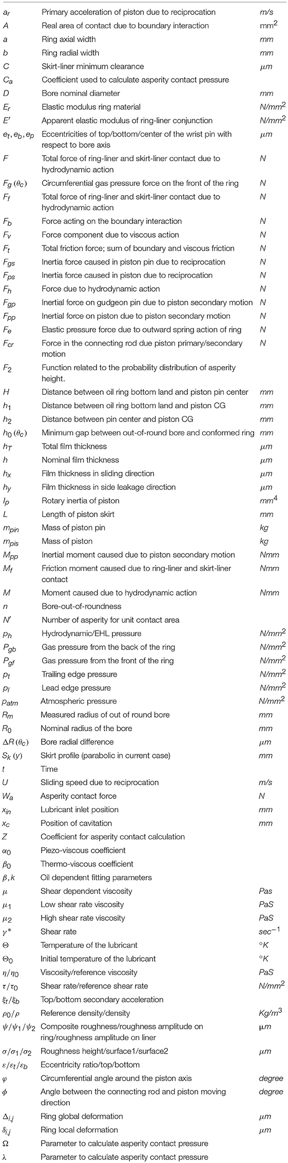
Notations
Keywords: piston subsystem, design optimization, skirt, strength, crown, von-Misses
Citation: Mishra PC and Kumar S (2019) Modeling for Design Optimization of Piston Crown Geometry Through Structural Strength and Lubrication Performance Correlation Analysis. Front. Mech. Eng. 5:17. doi: 10.3389/fmech.2019.00017
Received: 26 December 2018; Accepted: 27 March 2019;
Published: 30 April 2019.
Edited by:
Yu Tian, Tsinghua University, ChinaReviewed by:
Xiqun Lu, Harbin Engineering University, ChinaYoshitaka Nakanishi, Kumamoto University, Japan
Copyright © 2019 Mishra and Kumar. This is an open-access article distributed under the terms of the Creative Commons Attribution License (CC BY). The use, distribution or reproduction in other forums is permitted, provided the original author(s) and the copyright owner(s) are credited and that the original publication in this journal is cited, in accordance with accepted academic practice. No use, distribution or reproduction is permitted which does not comply with these terms.
*Correspondence: Prakash Chandra Mishra, prabasmishra73@gmail.com