Influence of MHD Lubrication and Textured Surface in EHL Line Contact
 Suresh Jadhav
 Gananath D. Thakre2
  Satish C. Sharma
- 1Tribology Laboratory, Department of Mechanical and Industrial Engineering, Indian Institute of Technology Roorkee, Roorkee, India
- 2Advanced Tribology Research Centre, CSIR, Indian Institute of Petroleum, Dehradun, India
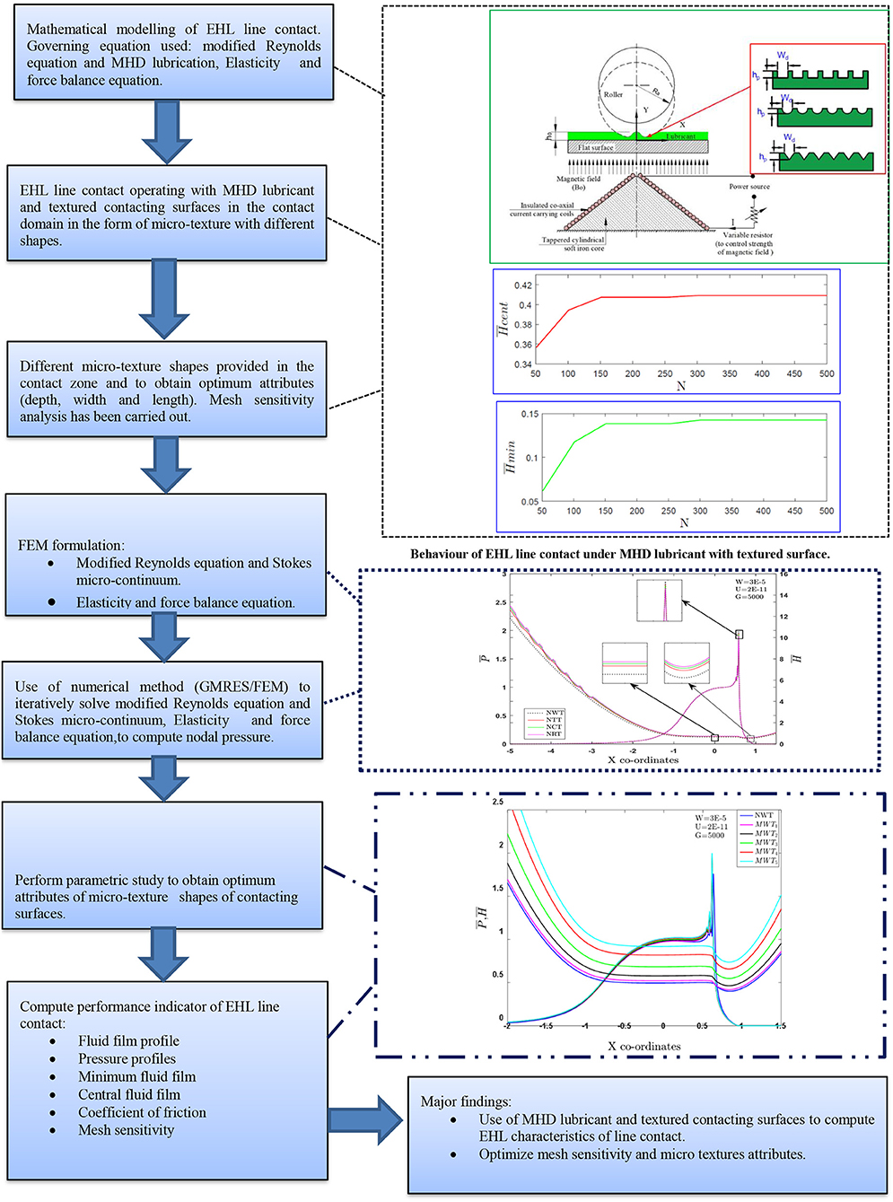
The present numerical study investigates the combined effect of micro-texture and magneto hydrodynamic lubrication behavior on the performance of elastohydrodynamic lubrication (EHL) line contact. Micro-textures, which are found in the inlet zone of a contacting surface, are studied, and modified Reynolds, elasticity, and load balance equations have been solved using Finite element analysis (FEA) and Generalized Minimal Residual Method (GMRES). A parametric study has been performed to optimize the micro-texture shapes in the contacting surfaces for different values of magneto hydrodynamic lubricant parameters. The numerical results show that increasing externally applied magnetic field and micro- texture shapes enhances the values of performance parameter of EHL line contact. Finally, the variation in the steady-state EHL characteristics pertaining to unidirectional pure sliding contacts due to an artificially produced inlet zone of micro-texture shapes (IZMTS) is investigated numerically. The enhancement in central and minimum film thickness is found to be up to 38 and 28% respectively, along with 33.28% reduction in coefficient of friction.
Introduction
Elastohydrodynamic lubrication (EHL) is a special form of hydrodynamic lubrication involving extremely high contact pressures leading to substantial increase in lubricant viscosity along with significant elastic deformation of surfaces. The most common examples of machine elements operating an EHL regime are the ones involving non-conformal contacts, similar to those observed in gears, cams, roller bearings and so on. Owing to the high contact loads, EHL films are extremely thin and, hence, the chance of direct surface contact is quite high. Therefore, high energy efficiency and premature failure is also of primary concern. Due to this reason, the coefficient of friction and fluid film thickness are the important design parameters requiring a high degree of accuracy for operating conditions (Dowson and Higginson, 1966). Nowadays, machines are operated under severe conditions; lubricants in the machine bearings undergo frequent changes in viscosity and density properties of fluid in such conditions. Lubricants having high thermal and electrical conductivity mixed with polymer additives are used to avert the abrupt variations in lubricant viscosity at high temperatures. MobilTM DTE 932 GT lubricant is a commercially available lubricant oil showing high electrical conductivity. Low viscosity lessens the load carrying capacity (LCC) which can be overcome by the use of an external magnetic field (Roberts, 1981). The study of electrical conducting lubricant in the presence of a magnetic field is categorized as magneto hydro dynamics (MHD) or hydro-magnetics. Alongside this, magnetic fields have a wide range of applications in both the research field and industry such as in power generation, crude oil purification, propulsion and accelerators. Numerical simulations on a wide curve rectangular parallel plate are carried out, and it is reported that a magnetic field presence leads to a substantial increase in the LCC and the response time of squeeze film (Lin et al., 2013). The impact of a transverse magnetic field over the behavior of MHD lubricant in fluid film bearing has been studied by numerous researchers (Elco and Hughes, 1962; Malik and Singh, 1980; Roberts, 1981). Several theoretical and experimental studies pertaining to the use of MHD lubricant in hydrostatic bearings (Maki et al., 1966), slider bearings (Das, 1999), journal bearings (Kamiyama, 1969; Hamza, 1991), and squeeze films (Chou et al., 2003) have been reported in the literature. However, the aforementioned studies lack the incorporation of deformation of the lubricating surface.
Over the last decade, modifications in surface topography (using micro/Nano 3-D geometric features) are emerging as a viable option for improving the contact performance of machine elements. The scale of fluid film and surface topography should be alike to observe perceptible influences on fluid properties i.e., pressure and velocity of emollient flow. The surface topography can be controlled by texturing with great accuracy. It has been observed from published literature that notable shapes such as triangular, rectangular, circular, elliptical, sinusoidal, and spherical shapes are commonly used for composing the specific types of texture patterns in published literature (Braun et al., 2014). The improvement in the fatigue life of the contacting surfaces operating in boundary/mixed lubrication regimes was demonstrated. However, the numerical investigation on the mechanism of life improvement in mixed lubrication was attempted (Zhai et al., 1997). Recently, it has been reported that a well-defined pattern in terms of size, shape and orientations of the surface features significantly improves the performance of concentrated contacts (Yu et al., 2013), experimentally demonstrating that the surface dimples can act as micro-reservoirs of lubricant which facilitate the fluid film formation even during the ultra-thin film lubrication. It is also stated that the deep micro feature causes reduction in the lubricant film thickness (Sudeep et al., 2015). Textured concentrated contacts are found to be beneficial in reducing the surface damage during the start-up and reversal of motions (Pettersson and Jacobson, 2003; Krupka et al., 2010). Under starved lubricated conditions, surface dimples are found to act as oil reservoirs, which not only supply lubricant to the contact by smearing but also act as wear particle traps (Hua et al., 1997). The geometric shapes of the dimples can influence the hydrodynamic lubrication of concentrated contacts (Zum Gahr et al., 2009). Micro-textures have proved to significantly enhance the tribological behavior of contacting surfaces in relative motion. Substantial advantages of surface micro textures in different practical applications have been revealed through the various theoretical and experimental findings published in literature (Etsion, 2005, 2013; Cupillard et al., 2008; Maharshi et al., 2018). In most of the studies mentioned in the literature, micro-textures are provided over the contact surface domain in the form of micro dimples. In EHL line contacts, film thickness is governed by the inlent zone (IZ) where the lubricating film builds up. The contacting surface is separated due to the hydrodynamic lift established in the IZ, which is mainly due to the converging shape of the gap (Habchi et al., 2008). Therefore, the focus of the present work is to investigate the combined influence of MHD and micro texture shapes (spherical, rectangle, and triangle) which are found in the IZ of EHL line contact. This study will, under different operating conditions, be helpful to tribologists and lubrication engineers around the globe.
Mathematical Formulation
The present work deals with a solution that combines a modified Reynolds equation, an elasticity equation, a rheology equation (density-pressure relation, viscosity-pressure relation) and a force balance equation. To handle such a highly non-linear problem, an analytical solution would be cumbersome. Therefore, a numerical method is used for mathematical modeling. Hence, one of the most popular numerical methods, the FEA approach, has been used to numerically simulate an EHL line contact as discussed in succeeding sub-sections.
Reynolds Equation
A schematic for EHL line contact under the effect of external transverse magnetic field is illustrated in Figure 1. The schematic diagram of EHL line contact comprises a tapered cylindrical soft iron core wrapped in insulated coaxial cables, a variable resistor, a lubricant and a power source. The lubricant used in the system has isothermal, electrically conducting and incompressible fluid properties. This system is exposed to transverse magnetic fields by making a constant current flow through the coaxial cables (which act as a solenoid) when on the power source is switched on. The variable resistor is used to control the magnitude of the electrical current, which in turn directs the strength of the transverse magnetic field; the cylindrical core guides the magnetic field in the fluid flow region in the desired direction. The laws of hydrodynamics are extended by inclusion of the magnetic force to momentum conservation equation. Under the presence of an externally applied uniform magnetic field (By) acting along the direction of lubricant film, the conducting lubricant is provided to the point of contact. For improving the life of the contacting surfaces, randomly distributed textures were created on the surface operating in boundary/mixed lubrication regimes. Micro-textures patterning, in terms of size, shape and orientation of the surface features, significantly improves the performance of concentrated contacts. A schematic representation of different micro-textures with spherical (Sph), rectangle (Rect), and triangle (Tri)shapes are presented in Figures 2A–C. Use of micro texturing and magneto hydrodynamic (MHD) lubricant may provide significant enhancement in the EHL performance characteristics. Assuming that there is a steady rate of flow, incompressible fluid, and ignoring any body force and fluid inertia (except Lorentz force), the Navier-Stokes (NS) and continuity equations are written as (Maki et al., 1966; Malik and Singh, 1980):

Figure 1. EHL line conjunction under the influence of external magnetic field.
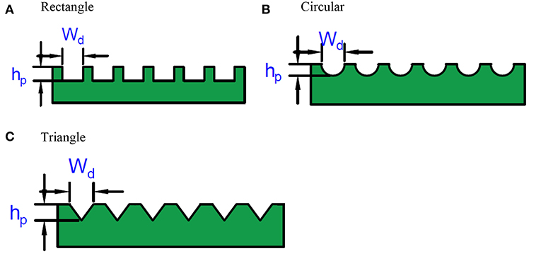
Figure 2. Micro textures shapes (A) Rectangle; (B) Circular; (C) Triangle.
Here is the Lorentz force. It is defined by the force exerted on a charge particle in a magnetic field (Bo), where is the current density. Simplifying momentum equation (Equation 1) along the x and y directions is expressed as (Maki et al., 1966; Kamiyama, 1969):
Ez is the component of an induced electric field in the “z” direction. In the present work, it is assumed that the surfaces are perfect insulators. Therefore, an electric field can be achieved by setting the flow of current at zero. The electric field in Equation 3 is obtained as;
To obtain velocity profile, no -slip boundary conditions are used as:
Integrating Equation (3) using the above mentioned boundary conditions (Equations 6, 7), and simultaneously solving Equation (5), we obtain the velocity of fluid in “x” direction which can be expressed as:
Here, Hm is characterized by the ratio of the electro-magnetic force to the viscous force and expressed as: . Substituting the value of u in Equation (2) gives:
Equation (9) is modified MHD Reynolds equation,
where is the MHD function and In limiting cases the MHD function lessens the unity: limHm → 0 ψ (, Hm) = 1 i.e., the Newtonian fluid. In this work, the following parameters are used for non-dimensionalization of the Reynolds equation:
The modified Reynolds equation can be expressed in non-dimensional form as:
where
Boundary conditions used for solving Reynolds equation are as follows:
At inlet: P = 0 at P = Xin
At outlet:
Elasticity Equation
The elasticity equation gives the shape of the lubricant film, which includes the elastic deformation for a given pressure distribution (Jin and Dowson, 1997). In this study, fluid film thickness has been modified to incorporate the micro textures (spherical, rectangular and triangular) and is expressed as:
Hmt represents the fluid film thickness component for a given micro-textures geometry.
For a textured surface with a spherical micro texture shape
For a textured surface with a rectangular micro texture shape;
For a textured surface with a triangular micro textures shape;
Density-Pressure Equation
Dimensionless form of density-pressure relation (Dowson and Higginson, 1959) is expressed as:
Viscosity-Pressure Equation
Dimensionless form of viscosity-pressure relation (Roelands et al., 1963) is given by:
Force Balance Equation
The pressure developed within the lubricant film supports the applied load. Therefore, pressure obtained from the Reynolds equation should satisfy the force equilibrium condition which is written in the dimensionless form as:
Coefficient of Friction
The governing equations are solved to obtain pressure distribution and film shape which is used to evaluate the coefficient of friction and is expressed in the dimensionless form (Kumar et al., 2008) as:
Finite Element Analysis
The governing equations have been solved using the standard Galerkin's method. Two noded linear isoparametric elements were used to discretize the fluid flow field. A mesh sensitivity analysis (MSA) has been taken into account to obtain an optimum mesh size of 451 elements for simulating the behavior of the lubricant flow field and is illustrated in Figure 3. The lubricant film pressure over an element is interpolated by applying a Lagrangian interpolation function. The residual form of Equation (10) can be written as:
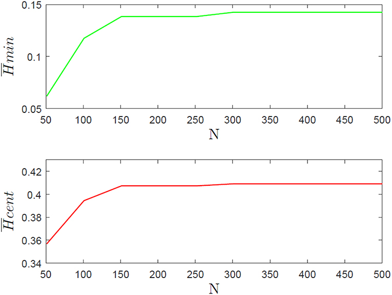
Figure 3. Mesh sensitivity test with total number of nodes (N).
Galerkin's method is adopted to obtain the below integral equation:
The differentiation of any two functions (f1, f2) is:
Using Equation (20), Equation (19) is transformed to,
The fluid film pressure over an element is approximated as:
The elemental system of the equation has been obtained to simplify the Equation (22) by integrating it part-wise as:
where
To obtain a global system of the equation in matrix form, the elemental system of Equation (23) is evaluated and assembled as:
Elasticity equation considering a new kernel (Lu et al., 2005, 2006) has been evaluated for elastic deformation as follows.
, here representing the kernel, can be written as:
is evaluated analytically when “X” is inside of “e”. In other circumstances, Gaussian quadrature should be utilized. Using Gaussian quadrature, force balance equation can be written as:
Using Gaussian quadrature, the coefficient of friction is expressed as:
Solution Procedure
In this study, the governing equations presented above involve complex mathematical models, the solution of which is carried out simultaneously with the help of finite element approach. In this approach, elemental equations are calculated and assembled to obtain the global system of equations. Nodal fluid film pressure is evaluated iteratively using GMRES Algorithm. The computation of elemental equations, its assembly and the iterative procedure is accomplished by developing computer code using MATLAB software. The micro texture is provided in the contact domain using parabolic and trapezoidal shapes. The detailed steps involved for the numerical simulation of EHL line contact with micro textures operated with electrically conducting lubricant (ECL) is presented in the flow chart shown in Figure 4.
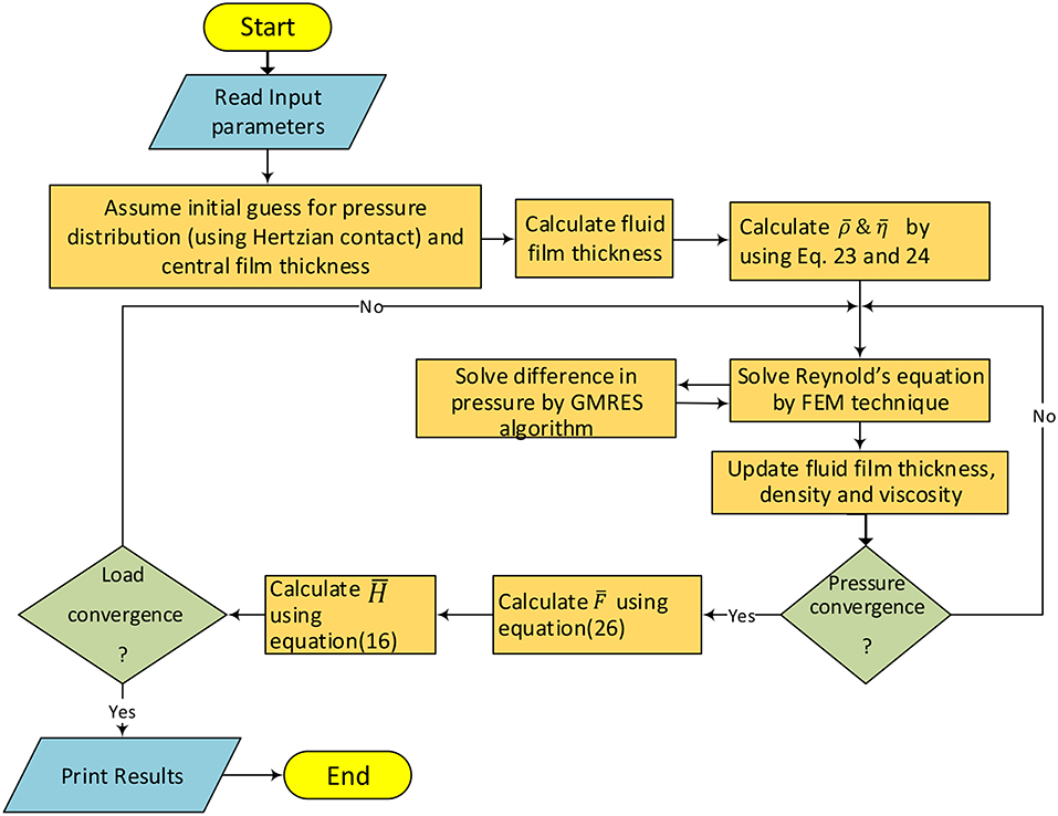
Figure 4. Solution scheme of EHL contact.
Model Validation
The developed computer code for EHL line contact model program is validated by comparing the computed results with the relevant data from literature. After going through the published literature, different studies (Ertel, 1945; Dowson, 1961, 1978; Wymer, 1972; Hamrock and Jacobson, 1984; Mohrenstein-Ertel, 1984; Yang and Wen, 1987; Pan and Hamrock, 1989; Dowson and Higginson, 2014) have been identified for comparison of conventional EHL line contact film thickness ( and ) with that of present study. Figures 5A,B represents the numerical result from the present model and from the conventional curve-fitting formulas. The film thickness values for EHL line-contact presented in this study agree well with typical film thickness formulas. Also, values evaluated from the developed source code have been compared with previous results (Hamrock and Jacobson, 1984). The comparative assessment of results obtained from both these studies has been illustrated in Table 1. The deviation of results of the present model from previous studies may be attributed to different solution schemes and grid sizes employed by the two studies. These validations with different studies justify the computer program which was developed in the present work, and shows it is applicable for conventional EHL as well as textured EHL line contact operated with MHD lubricant.
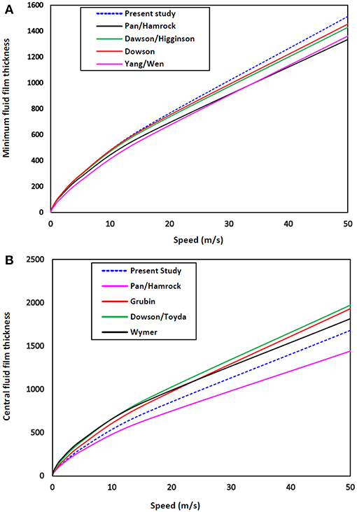
Figure 5. Comparison with the results from classic EHL line-contact film thickness formulas: (A) minimum film thickness, and (B) central film thickness.
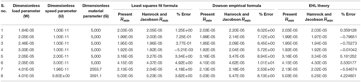
Table 1. Influence of dimensionless load, speed and material parameters on minimum fluid film thickness of elastohydrodynamic lubrication line contact (Hamrock and Jacobson, 1984).
Result and Discussion
The effect of each of the non-dimensional design variables i.e., magneto hydrodynamic (MHD) lubricant and micro texture geometry (spherical, rectangle, triangle) and the operating parameters (i.e., dimensionless speed, load and material parameter) has been investigated by conducting a parametric study on the performance characteristics of EHL line contacts. MHD lubricant is characterized by the Hartmann number (Hm), which signifies the influence of externally applied magnetic fields upon the performance characteristics of EHL line contact. As the value of “Hm” approaches zero, Equation (9) reduces to the Reynolds equation (i.e., non-conducting electrical lubricant), with lubricant considered to behave as Newtonian fluid. Table 2 presents operating parameters which have been selected from available literature (Lin et al., 2013; Daliri et al., 2015) for the present work. A steady state lubricant film pressure distribution is achieved by a coupled solution of different governing Equations (9, 12, 13, 14, and 16) satisfying the boundary conditions. The effect of aforementioned parameters is presented on the dimensionless performance parameters such as and thickness, pressure distribution profile, fluid film thickness profile and coefficient of fiction etc. in the subsequent sub sections. Subscript 2 and 4 represent the value of MHD lubricant parameters (Hm).
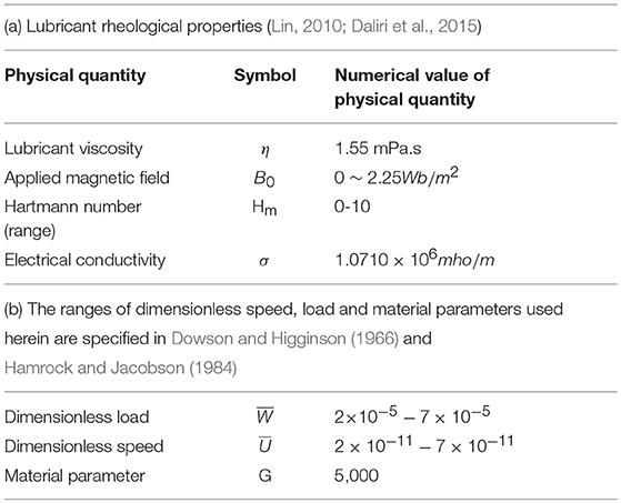
Table 2. Numerical data for present study.
Micro Texture Attributes
The influence of micro dimple depths on lubricant film thickness and pressure profile is illustrated in Figures 6A–F. Micro-dimple has been provided in the IZ of EHL line contacts in the form of rectangular, spherical and triangular shapes. The depth of micro-dimples varies between 0.2 and 1.2. The variation in fluid film shape can be observed from film thickness profiles for triangular, spherical and rectangle dimple for the Newtonian fluid. These micro-dimples are of different depths so that their behavior can be compared to observe the influence of the depth of micro-dimples. It can be seen that there is an incremental increase in the film thickness and pressure peak from 0.2 to 0.8 depth of micro-dimples. This increase in film thickness is caused by a fluid flowing through the trailing edge of the micro-dimples because of different velocities of roller/cylindrical surfaces. The fluid flows through the contact with the velocity of the surface so that fluid entrapped within the micro-dimple goes ahead of it, and the pressure gradient within the micro-dimples results in elastic deformation of the sliding surfaces. This process is connected with the location of the micro-dimple within a high-pressure region of the contact (Yu and Sadeghi, 2001; Etsion et al., 2004; Etsion, 2005). The profile of film thickness and fluid pressure depicted in Figures 6E,F shows the obvious reduction of both film thickness and pressure when downstream of these relatively deep micro-dimples. As the dimple depth continues to increase, the backflow of lubricant comes into the picture. As a result of this, film thickness decreases, which in turn results in an increased coefficient of friction. However, as the depth of the micro dimples increases beyond a certain limit the LCC reduces. Load support mechanism in the presence of shallow micro dimples causes hydrodynamic pressure to build up in the converging zone of the micro dimples and also causes cavitation in the diverging section of the micro dimples (Yu and Sadeghi, 2001; Cupillard et al., 2008). Lastly, the micro-dimples with a depth beyond “1.0” causes reduction in the film thickness and pressure gradients. It has also been observed that a cross-sectional area of the rectangle dimple offers additional space for the fluid film thickness to build up and hence increase the LCC (Elco and Hughes, 1962).
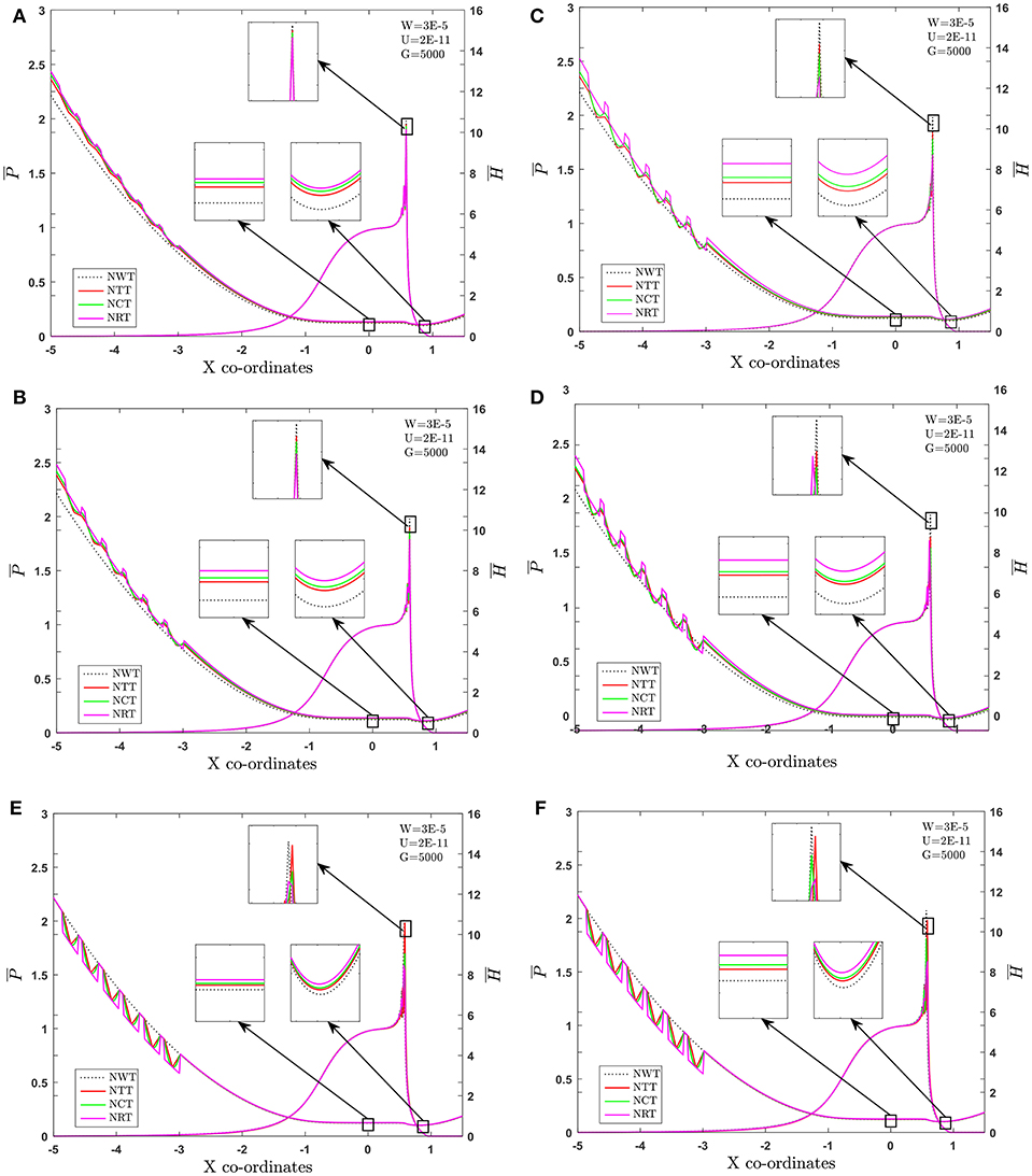
Figure 6. Effect of different micro depth [(A) 0.2, (B) 0.4, (C) 0.6, (D) 0.8, (E) 1.0, and (F) 1.2] of micro dimple on fluid film thickness.
Effect of MHD and Micro Texture on and
Load () Parameter
The combined effect of MWT2 and MWT4 and different micro texture shape (MTS) on fluid film profile and pressure distribution in an EHL line contact for , while the are held fixed is depicted in the Figures 7A,B. As is increased, the value of the pressure peak increases and and decreases. It can be seen from Figures 7A,B, that and increase with the use of MWT2 and MWT4 and different MTS in comparison with smooth surface. When the contacting surface operates with the ECL, the percentage increase in the value of is 13.28% and is 17.33%, vis-à-vis Newtonian fluid for smooth case. Further, maximum percentage variation of is observed to be 38.24%, and is found to be 46.37% for the case of the combined effect of rectangular texture and Hm = 2 in comparison with other texture surface and Newtonian fluid. Furthermore, for the combined effect of Hm = 4 and MTS, the value of and increases can be seen from Figure 7B. Quantitatively, increases by 13.28% and by 15.17 % with the use of Hm = 4 and, combined with the influence of MRT4, is increased by 43.28% and 46.37%, vis-à-vis Newtonian fluid. The variation of the pressure spike from Figures 7A,B is found to be of the order of 1.78 and 2.00% for the case of MWT2 and MWT4, respectively, and 1.67 and 1.97% for the case of combined effect of MRT2 and MRT4, respectively. These results may be attributed to the dominance of an externally applied magnetic field, resulting in increased apparent viscosity of lubricant, and are within the range of elastic deformation. Micro-texture is behaving as an oil reservoir, which provide lubricant at the contact by smearing and also act as trap for wear particles during the sliding motion of concentrated contacts. Specifically, rectangular texture outperforms other texture surfaces in generating additional hydrodynamic pressure, which can be beneficial in increasing LCC of the contact surfaces. In the inlet zone, the contribution of convective term across the fluid film was quite significant. The IZ pressure build-up and change of fluid viscosity due to piezo viscous effect determine the film generation capability. However, the micro-texture shapes affect the inlet pressure sweep and variations in the hydrodynamic pressure generation (Hsiao and Hamrock, 1992). The following pattern has been noted for and for as:
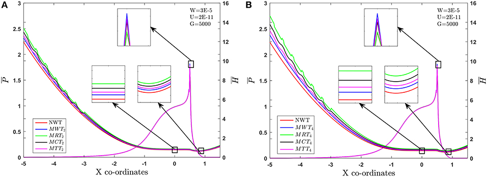
Figure 7. Combined effect of Hm (A) 2, (B) 4, and micro textures shapes in inlet zone for .
Speed () Parameter
The numerically simulated results for and at are presented in Figures 8A,B. The trends in these figures indicate that the use of different MTS and MHD lubricant parameters significantly increases the value of and . From Figures 8A,B, it can be noticed that the percentage changes in the value of and are 12.33 and 15.18% for the case of Hm = 2 over the Newtonian fluid. Further, it can be noticed that the value of and increases by 21.07 and 26.95%, due to the combined effect of MRT2 as compared to NWT. Furthermore, by increasing the strength of an externally applied magnetic field i.e., Hm = 4, the increase in values of and are found to be 23.63 and 29.82%. Later, the combined effect of Hm = 4 and a rectangular texture means the values of and are increased by 30.92 and 42.62% respectively. It can be clearly observed that the MRT causes a substantial accession in the value of and over the other texture surface and Newtonian lubricant without texture (NWT). Variation in the pressure peak from Figures 8A,B is found to be of the order of 1.98 and 2.18% for the case of MWT2 and MWT4, and 1.87, 1.98% for the case of the combined effect of MRT2 and MRT4. In IZ, the contribution of the convective term across the fluid film is quite significant. Thus, the increase in the lubricant viscosity and deformation of surfaces due to high contact pressures are sufficient enough to cause elastic deformation, and thick enough lubricant film is formed between contacting surfaces. From this, the following trend for and can be observed as indicated below:
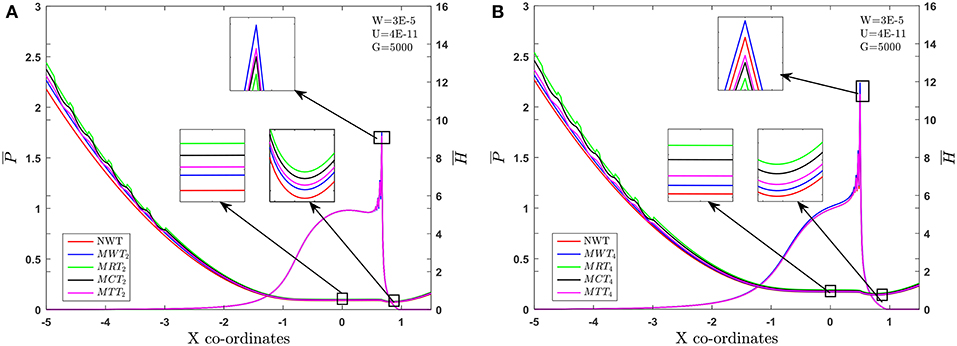
Figure 8. Combined influence of Hm (A) 2, (B) 4, and micro textures shapes in inlet zone .
Coefficient of Friction ()
Figures 9A,B depicts the comparison of the coefficient of friction () at different operating dimensionless load parameters. The value of decreases with an increase in the value for all the cases considered here. It can be observed from Figure 9A that the change of using a rectangular micro texture is −9.78%, as compared to NWT. Further, percentage reduction in the coefficient of friction () for the case of MRT2 is found to be −28.48% in comparison with Newtonian fluid. Furthermore, the combined influence of MRT4 leads to a percentage reduction of −35.30%, vis-a vis Newtonian fluid corresponding to . From Figure 9B, it is seen that MRT4 provides a lower value of than that of other MTS. It has been noticed from the results depicted in Figure 9B that the EHL line conjunction with MHD lubricant parameters engender lower coefficients of friction (). The aforesaid decrease in is caused by a lower contact zone viscosity due to localized pressure peaks in the presence of MTS and an externally applied magnetic field. An increase in the fluid film thickness tends to reduce as the area available for flow increases. MTS act as a lubricant reservoir, thereby enhancing EHL performance characteristics of line contacts, which leads to lower friction compared to smooth surfaces (Kumar et al., 2008). From the computed results, the following general pattern has been obtained for .
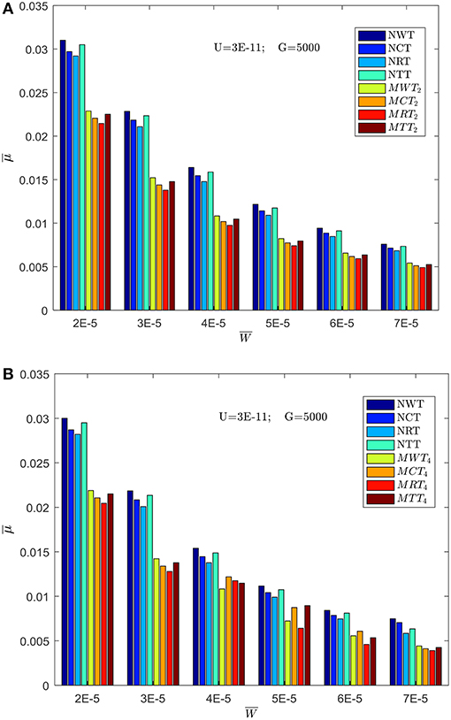
Figure 9. Effect of MHD lubricant parameter [Hm (A) 2, (B) 4] and MTS on coefficient of friction in the inlet zone of EHL line contact at U = 3 × 10⁻¹¹; G = 5, 000.
Pressure Distribution () and Fluid Film Profile ()
The combined effect of MTS and MHD lubricant on the pressure distribution and fluid film thickness profile are depicted in Figures 10A,B. It can be observed from Figure 10A that the presence of different texture surface increases the value of and over the non-texture surfaces. The percentage rises in the values of and are 14.22, 12.13, and 11.56% in regards to rectangular, circular and triangular shapes, respectively, over the smooth surface for the Newtonian fluid. The use of a rectangular texture in the contacting surface leads to a lower value of pressure spike by 1.67%, when compared with other MTS and Newtonian fluid. The reason for a lower value pressure spike could be resistance to the influx of fluid within the micro texture which depends on the geometry of MTS, hence variation in lubricant film pressure exists for each of MTS. It can also be seen from Figure 10B that with the increase in the externally applied magnetic field (Hm), pressure spike and fluid film thickness also increases progressively. Percentage rises in the value of pressure spikes, in comparison with Newtonian fluid, are observed to be in the order 1.91, 1.93, 1.95, 1.97, and 1.99%, corresponding to Hm = 1, 2, 3, 4, and 5 respectively for the smooth surface. Furthermore, a similar trend is noticed for and , with the increasing value of Hm. The maximum percentage increment in the value of is found to be in order of 4.37, 11.85, 15.70, 19.05, and 21.73%, and percentage rise in the value of is observed to be in order of 6.34, 13.93, 18.98, 22.58, and 25.45%. The increment in the and due to the presence of Lorentz force and increases the velocity of fluid flowing between contact surface. Consequently, more of the lubricant accumulates in the clearance space between the contacting surface. This will eventually lead to an adequate amount of contact pressure and to cause deformation elastically. This increase in and , and the lowering value of the pressure peak can be attributed to the rectangular shape which also acts as a micro-step bearing and/or a micro-wedge, tending to produce thicker fluid film. Specifically, a rectangular shape outperforms other micro-texture surface in generating additional hydrodynamic pressure, which can be beneficial in increasing LCC of the contact surface. Also, an increase in the externally applied magnetic field results in an increase of apparent viscosity, LCC and lubricant film thickness. In the inlet zone, the contribution of convective terms across the fluid film was quite significant.
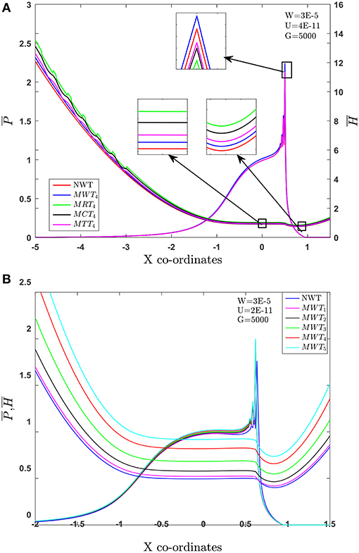
Figure 10. Effect of MHD lubricant and micro texture shapes in inlet zone of EHL line contact at W = 3 × 10⁻⁵; U = 2 × 10⁻¹¹; G = 5,000. (A) Hm = 4. (B) Without texture and Hm variation.
Conclusion
In the present study, the EHL line contact simulation results are presented to study the performance parameters behavior during MHD lubricant, considering different MTS. Furthermore, the effect of MTS in the IZ on EHL characteristics has been investigated. A and film thickness enhancement of more than 28.75 and 38.23%, over conventional EHL line contact, is predicted for the case of MRT4 under the present operating conditions. Furthermore, this enhancement in the film thickness is found to increase with increasing value of Hm and decreasing value coefficient of friction. Enhancement for film thickness of up to 11.23, 10.43, and 9.76%, and for up to 10.23, 9.55, and 8.73%, has been achieved due to the presence of MHD lubricant and IZMTS under the present operating conditions. The percentage increment in due to Hm and IZMTS is higher than that of . Besides, film thickness enhancement, externally applied magnetic field and IZMTS also shows significant reduction in COF. The effectiveness of MTS depth is found to increase up to “0.8”. However, the effectiveness of IZMTS is ensured only when it is located completely within the IZ. The present analysis is intended to be useful to designers and practice engineers for judicious selection of Hm number and MTS under the different operating conditions.
Author Contributions
All authors listed have made a substantial, direct and intellectual contribution to the work, and approved it for publication.
Conflict of Interest Statement
The authors declare that the research was conducted in the absence of any commercial or financial relationships that could be construed as a potential conflict of interest.
References
Braun, D., Greiner, C., Schneider, J., and Gumbsch, P. (2014). Efficiency of laser surface texturing in the reduction of friction under mixed lubrication. Tribol. Int. 77, 142–147. doi: 10.1016/j.triboint.2014.04.012
Chou, T.-L., Lai, J.-W., and Lin, J.-R. (2003). Magneto-hydrodynamic squeeze film characteristics between a sphere and a plane surface. J. Marine Sci. Technol. 11, 174–178.
Cupillard, S., Glavatskih, S., and Cervantes, M. (2008). Computational fluid dynamics analysis of a journal bearing with surface texturing. Proc. Inst. Mech. Eng. J J. Eng. Tribol. 222, 97–107. doi: 10.1243/13506501JET319
Daliri, M., Jalali-Vahid, D., and Rahnejat, H. (2015). Magneto-hydrodynamics of couple stress lubricants in combined squeeze and shear in parallel annular disc viscous coupling systems. Proc. Inst. Mech. Eng. J J. Eng. Tribol. 229, 578–596. doi: 10.1177/1350650114556398
Das, N. (1999). A study of optimum load capacity of slider bearings lubricated with power law fluids. Tribol. Int. 32, 435–441. doi: 10.1016/S0301-679X(99)00072-9
Dowson, D. (1978). “A central film thickness formula for elastohydrodynamic line contacts, Elastohydrodynamics and related topics,” in Proceedings 5th Leeds–Lyon Symposium.
Dowson, D., and Higginson, G. (1959). A numerical solution to the elasto-hydrodynamic problem. J. Mech. Eng. Sci. 1, 6–15. doi: 10.1243/JMES_JOUR_1959_001_004_02
Dowson, D., and Higginson, G. (1966). Elasto-Hydrodynamic Lubrication Pergamon Press. Oxford Google Scholar.
Dowson, D., and Higginson, G. R. (2014). Elasto-Hydrodynamic Lubrication: International Series on Materials Science and Technology. Elsevier.
Elco, R., and Hughes, W. (1962). Magnetohydrodynamic pressurization of liquid metal bearings. Wear 5, 198–212. doi: 10.1016/0043-1648(62)90004-2
Ertel, A. M. (1945). Hydrodynamic Calculation of Lubrication of Curved Surfaces (Gears, Rolling Bearings, Highly Loaded Journal Bearings etc.), Nauk: Akad.
Etsion, I. (2005). State of the art in laser surface texturing. J. Tribol. 127, 248–253. doi: 10.1115/1.1828070
Etsion, I. (2013). Modeling of surface texturing in hydrodynamic lubrication. Friction 1, 195–209. doi: 10.1007/s40544-013-0018-y
Etsion, I., Halperin, G., Brizmer, V., and Kligerman, Y. (2004). Experimental investigation of laser surface textured parallel thrust bearings. Tribol. Lett. 17, 295–300. doi: 10.1023/B:TRIL.0000032467.88800.59
Habchi, W., Eyheramendy, D., Vergne, P., and Morales-Espejel, G. (2008). A full-system approach of the elastohydrodynamic line/point contact problem. J. Tribol. 130:021501. doi: 10.1115/1.2842246
Hamrock, B. J., and Jacobson, B. O. (1984). Elastohydrodynamic lubrication of line contacts. ASLE Transac. 27, 275–287. doi: 10.1080/05698198408981572
Hamza, E. (1991). The magnetohydrodynamic effects on a fluid film squeezed between two rotating surfaces. J. Phys. D Appl. Phys. 24:547. doi: 10.1088/0022-3727/24/4/005
Hsiao, H.-S. S., and Hamrock, B. J. (1992). A complete solution for thermal-elastohydrodynamic lubrication of line contacts using circular non-Newtonian fluid model. J. Tribol. 114, 540–551. doi: 10.1115/1.2920916
Hua, D., Qiu, L., and Cheng, H. (1997). Modeling of lubrication in micro contact. Tribol. Lett. 3, 81–86. doi: 10.1023/A:1019131727427
Jin, Z., and Dowson, D. (1997). A general analytical solution to the problem of microelastohydrodynamic lubrication of low elastic modulus compliant bearing surfaces under line contact conditions. Proc. Inst. Mech. Eng. C J. Mech. Eng. Sci. 211, 265–272. doi: 10.1243/0954406971522033
Kamiyama, S. (1969). Magnetohydrodynamic journal bearing (report 1). J. Lubric. Technol. 91, 380–386. doi: 10.1115/1.3554944
Krupka, I., Svoboda, P., and Hartl, M. (2010). Effect of surface topography on mixed lubrication film formation during start up under rolling/sliding conditions. Tribol. Int. 43, 1035–1042. doi: 10.1016/j.triboint.2009.12.017
Kumar, P., Jain, S., and Ray, S. (2008). Thermal elastohydrodynamic lubrication of rolling/sliding line contacts using a mixture of Newtonian and power law fluids. Proc. Inst. Mech. Eng. J J. Eng. Tribol. 222, 35–49. doi: 10.1243/13506501JET297
Lin, J.-R. (2010). Mhd steady and dynamic characteristics of wide tapered-land slider bearings. Tribol. Int. 43, 2378–2383. doi: 10.1016/j.triboint.2010.07.010
Lin, J.-R., Chu, L.-M., Hung, C.-R., and Wang, P.-Y. (2013). Derivation of two-dimensional couple-stress hydromagnetic squeeze film Reynolds equation and application to wide parallel rectangular plates. Meccanica 48, 253–258. doi: 10.1007/s11012-012-9613-7
Lu, H., Berzins, M., Goodyer, C., and Jimack, P. (2005). High-order discontinuous Galerkin method for elastohydrodynamic lubrication line contact problems. Int. J. Numer. Methods Biomed. Eng. 21, 643–650. doi: 10.1002/cnm.781
Lu, H., Berzins, M., Goodyer, C., Jimack, P., and Walkley, M. (2006). Adaptive high-order finite element solution of transient elastohydrodynamic lubrication problems. Proc. Inst. Mech. Eng. J J. Eng. Tribol. 220, 215–225. doi: 10.1243/13506501JET134
Maharshi, K., Mukhopadhyay, T., Roy, B., Roy, L., and Dey, S. (2018). Stochastic dynamic behaviour of hydrodynamic journal bearings including the effect of surface roughness. Int. J. Mech. Sci. 142, 370–383. doi: 10.1016/j.ijmecsci.2018.04.012
Maki, E. R., Kuzma, D. C., and Donnelly, R. J. (1966). Magnetohydrodynamic lubrication flow between parallel plates. J. Fluid Mech. 26, 537–543. doi: 10.1017/S002211206600137X
Malik, M., and Singh, D. (1980). Analysis of finite magnetohydrodynamic journal bearings. Wear 64, 273–280. doi: 10.1016/0043-1648(80)90133-7
Mohrenstein-Ertel, A. (1984). “Die Berechnung der hydrodynamischen Schmierung gekrümmter Oberflächen unter hoher Belastung und Relativbewegung, überarbeitet,” in Fortschritt-Berichte der VDI-Zeitschriften Reihe, eds O. R. Lang and P. Oster.
Pan, P., and Hamrock, B. (1989). Simple formulas for performance parameters used in elastohydrodynamically lubricated line contacts. J. Tribol. 111, 246–251. doi: 10.1115/1.3261900
Pettersson, U., and Jacobson, S. (2003). Influence of surface texture on boundary lubricated sliding contacts. Tribol. Int. 36, 857–864. doi: 10.1016/S0301-679X(03)00104-X
Roberts, W. (1981). Tribology in nuclear power generation. Tribol. Int. 14, 17–28. doi: 10.1016/0301-679X(81)90025-6
Roelands, C., Vlugter, J., and Waterman, H. (1963). The viscosity-temperature-pressure relationship of lubricating oils and its correlation with chemical constitution. J. Basic Eng. 85, 601–607. doi: 10.1115/1.3656919
Sudeep, U., Tandon, N., and Pandey, R. (2015). Performance of lubricated rolling/sliding concentrated contacts with surface textures: a review. J. Tribol. 137:031501. doi: 10.1115/1.4029770
Wymer, D. G. (1972). Elastohydrodynamic Lubrication of a Rolling Line Contact. (Ph.D Thesis) University of London.
Yang, P., and Wen, S. (1987). A New Solution Method for Line Contact EHL Problems and New Film Thickness Formulae. Technical Report, Tsinghua University.
Yu, H., Huang, W., and Wang, X. (2013). Dimple patterns design for different circumstances. Lubric. Sci. 25, 67–78. doi: 10.1002/ls.168
Yu, T. H., and Sadeghi, F. (2001). Groove effects on thrust washer lubrication. J. Tribol. 123, 295–304. doi: 10.1115/1.1308014
Zhai, X., Chang, L., Hoeprich, M., and Nixon, H. P. (1997). On mechanisms of fatigue life enhancement by surface dents in heavily loaded rolling line contacts. Tribol. Transac. 40, 708–714. doi: 10.1080/10402009708983712
Zum Gahr, K.-H., Wahl, R., and Wauthier, K. (2009). Experimental study of the effect of microtexturing on oil lubricated ceramic/steel friction pairs. Wear 267, 1241–1251. doi: 10.1016/j.wear.2008.12.108
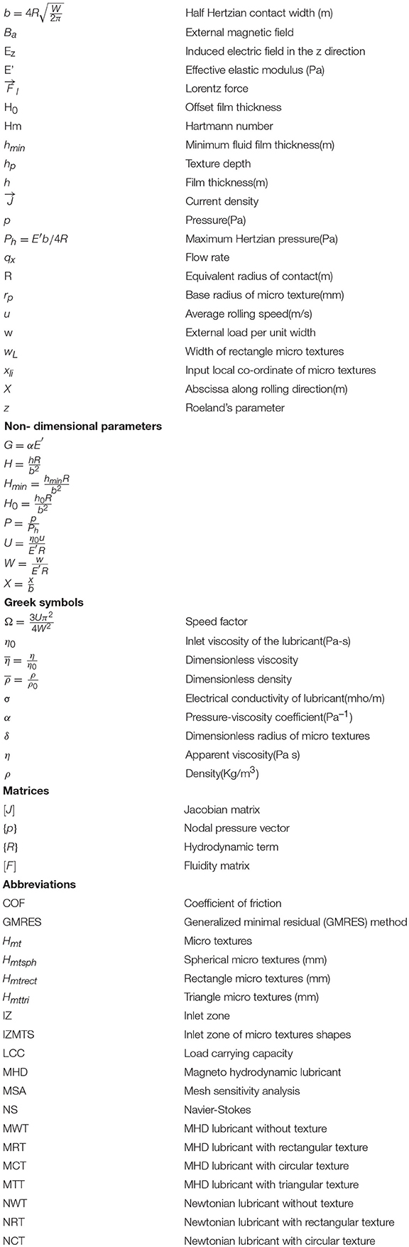
Nomenclature
Keywords: EHL, line contact, MHD lubrication, micro textures, coefficient of friction, finite element method, GMRES
Citation: Jadhav S, Thakre GD and Sharma SC (2019) Influence of MHD Lubrication and Textured Surface in EHL Line Contact. Front. Mech. Eng. 5:33. doi: 10.3389/fmech.2019.00033
Received: 10 December 2018; Accepted: 28 May 2019;
Published: 20 June 2019.
Edited by:
Giuseppe Carbone, Politecnico di Bari, ItalyReviewed by:
Yoshitaka Nakanishi, Kumamoto University, JapanCarmine Putignano, Politecnico di Bari, Italy
Copyright © 2019 Jadhav, Thakre and Sharma. This is an open-access article distributed under the terms of the Creative Commons Attribution License (CC BY). The use, distribution or reproduction in other forums is permitted, provided the original author(s) and the copyright owner(s) are credited and that the original publication in this journal is cited, in accordance with accepted academic practice. No use, distribution or reproduction is permitted which does not comply with these terms.
*Correspondence: Suresh Jadhav, sgj332@gmail.com; Satish C. Sharma, sshmefme@iitr.ac.in