Macroscopic Modeling of Fingerpad Friction Under Electroadhesion: Possibilities and Limitations
 Markus Heß
 Fabian Forsbach
- Institute of Mechanics, Technische Universität Berlin, Berlin, Germany
Electrovibration is one of the key technologies in surface haptics. By inducing controlled electrostatic forces, the friction within a sliding contact between the human finger and a capacitive screen is modulated, which in turn gives effective tactile feedback to the user. Such powerful haptic displays can be built into mobile phones, tablets, navigation devices, games consoles and many other devices of consumer electronics. However, due to the layered structure and complex material of human skin, the underlying contact mechanical processes have not yet been fully understood. This work provides new continuum-based approaches to macroscopic modeling of the electro-adhesive frictional contact. A solution of pure normal contact between a human finger and a rigid, smooth plane under electroadhesion is derived by applying Shull's compliance method in the extended regime of large deformations. Based on these results and assuming pressure-controlled friction, a model for the sliding electro-adhesive contact is developed, which adequately predicts the friction force and coefficient of friction over the whole range of relevant voltages and applied normal forces. The experimentally observed area reduction caused by the tangential force is incorporated in a more empirical than profound contact mechanical way. This effect is studied with the help of a two-dimensional finite element model of the fingertip, assuming non-linear elastic material for the skin tissue. Although the simulations are restricted to non-adhesive tangential contacts, they show a significant reduction of the contact area, which is caused by large deformations of the non-linear elastic material around the distal phalanx. This result indicates that adhesion is only of secondary importance for the area reduction.
Introduction
Understanding contact mechanics and friction of human skin is a great challenge for the tribological community. Human skin is characterized by a complex layered structure of non-linear viscoelastic material and a specific surface topography. In addition, its hydration level as well as moisture at its surface can strongly influence grip and touch properties. Especially with regard to tactile perception skin tribology is not yet fully understood (Derler and Gerhardt, 2012; van Kuilenburg et al., 2015). In this respect, improved knowledge is urgently needed as it plays a major role in the rapidly growing field of robotic and haptic applications. One key technology in surface haptics is electrovibration, which is based on the polarization of a fingerpad pressed in contact with an AC voltage supplied surface coated by an insulating layer. When the fingerpad is moved over the substrate, the user perceives a characteristic feeling which can be altered by controlling the shape, amplitude and frequency of the voltage (Vardar et al., 2017). In this way, the user can get effective tactile feedback. A schematic representation of such an electromechanical frictional contact between the fingerpad and touchscreen under electrovibration is depicted in Figure 1.
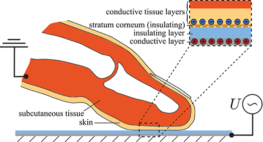
Figure 1. Schematic representation of the electromechanical frictional contact between the index fingertip and touchscreen.
Despite numerous experimental studies in this area, several effects are not yet sufficiently understood (Sirin et al., 2019b). Above all, there is a lack of well-founded models that correctly reflect the interaction between contact mechanics and electrodynamics. These models should not only provide good results for a single measured quantity like the friction force, but rather all other contact mechanical quantities, particularly the contact area, must also be correctly mapped on the way there. Excellent modeling from an electrodynamic point of view can be found in the works by Shultz et al. (2015) and Shultz et al. (2018) as well as Nakamura and Yamamoto (2017). From the point of view of contact mechanics, however, the simplest approaches are chosen. Promising multiscale approaches that cover both electrodynamics and contact mechanics in a suitable manner include the works by Persson (2018) and Sirin et al. (2019a).
Following the current Research Topic “contact mechanics perspective of tribology,” we focus exclusively on macroscopic modeling. We define a model as “macroscopic” if it is based on the apparent or ridge contact area. Smaller scales are not taken into account! On this macro scale some effort has been made to map voltage-induced friction as well. In this context, reference is made to Vodlak et al. (2016), Heß and Popov (2019) as well as Argatov and Borodich (2020). The work by Vodlak et al. focus on the assessment of two analytical models of electrovibration based on the parallel-plate capacitor by comparisons with experimental results published in literature. The approach proposed by Heß and Popov exploits the close analogy of electroadhesive contacts to classical adhesion theories based on van der Waals forces. However, this model provides insufficient results with respect to the contact area as a function of the normal force, since the original theory by Johnson et al. (1971) is applied. The interesting extension in the work by Argatov and Borodich is that it also takes non-linear elastic material behavior into account. However, a simple Winkler-Fuss model is mainly used, which is why it should generally be checked whether the three-dimensional contact mechanical behavior of the adhesive fingerpad contact can be mapped correctly. During the preparation phase of this manuscript another work on the same topic was published by Basdogan et al. (2020). Their model is based on the original theory of Johnson, Kendall and Roberts applicable for parabolic contacts of linear elastic materials. Therefore, the inhomogeneous, non-linear elastic finger material is replaced by a (fictive) homogeneous linear elastic one. A further characteristic approach of the model is the assumed proportionality between the real and apparent contact area, which is chosen in accordance with the results of recent multi-scale calculations (Ayyildiz et al., 2018; Sirin et al., 2019a).
As stated above, the aim of the present work is to develop a “macroscale” model which correctly reproduces all contact mechanical quantities and effects arising from the electro-adhesive frictional contact between the fingerpad and touchscreen. Since the tangential contact model is based on the solution of the pure normal contact, it is necessary to derive a robust model for the normal contact under electroadhesion.
Therefore, the present manuscript is structured as follows: First a novel model for the pure normal contact under electroadhesion is developed by application of the compliance method in the extended regime of large deformations and non-linear elastic materials. The integration of electroadhesion is realized by an idea of Popov and Heß (2018). Based on the resulting function of the ridge contact area in terms of applied voltage and normal force, an extended model for the sliding electro-adhesive contact is developed in Chapter Tangential Contact with Electroadhesion. This chapter begins with a study of the origins of the experimentally observed area reduction in frictional contact by means of adhesion theory and a non-adhesive two-dimensional finite element model of the fingertip accounting for the large deformations and non-linear elastic material behavior. In agreement with the FE results and recent studies, the area reduction is then incorporated in a model for pressure-controlled sliding friction in an empirical way. Finally, the developed model is compared to recent experimental results. Some conclusive remarks and a short discussion close the manuscript.
Normal Contact With Electroadhesion
Although the main objective of this study is to develop a model for sliding friction of a fingerpad over a smooth surface under electroadhesion, the preliminary investigation of pure normal contact is mandatory. The solution of the normal contact problem must be reproduced correctly in the limit of a vanishing tangential force, for both cases, with and without electroadhesion. In particular, the model for calculating the reduction of the contact area in the state of full slip requires precise knowledge of the contact area under pure normal loading with switched-on electroadhesion. While section Theoretical Background is devoted to the repetition and discussion of the theoretical principles to be applied, in section Application to Fingerpad in Contact with Capacitive Screen they are used to solve the normal contact between finger and capacitive screen under electroadhesion.
Theoretical Background
The model for normal contact under electroadhesion is essentially based on two fundamental principles, which are briefly repeated here. From a contact mechanical point of view, the focus lies on Shull's compliance method, which was originally designed for linear elastic material behavior. Its extended application to non-linear elastic material is not very well-known. According to Heß and Popov (2019), the incorporation of electrostatic attraction into the model is done by calculating the work of electroadhesion as well as the electrostatic force per unit area, which also includes the concept of the equivalent air gap.
Shull's Compliance Method—Generalized Version of the JKR-Theory
In analogy to the energy-based derivation of the original theory by Johnson et al. (1971), Shull and coworkers (Shull et al., 1998; Shull, 2002) developed a method which enables obtaining the solution of a more arbitrary adhesive normal contact problem from the known solution of the corresponding non-adhesive one. This method is called “compliance method” and represents a generalized version of the JKR-theory. Its applicability is neither restricted to homogeneous materials nor to circular contact areas, but linear material behavior is required. The main results of the compliance method are the following expressions for the elastic energy release rate G:
where FN and δ are the normal force and indentation depth of the adhesive contact. F1 and δ1 refer to the values of the corresponding non-adhesive contact and S denotes the contact stiffness defined by:
After equating the energy release rate G with the thermodynamic work of adhesion w, Equation (1) leads to:
Recently Equations (3) and (4) have been rediscovered and more precise restrictions concerning their applicability have been added (Ciavarella, 2018; Popov, 2018). The main assumption is that the sequence of contact configurations in an adhesive contact should be the same as that of contact configurations in a non-adhesive one. For this reason, the method cannot be generally applied to rough contacts. However, in some cases it seems to provide a good approximation of the adhesive solution. Furthermore, it should be stressed that the application to non-linear elastic material behavior, which characterizes human skin tissue, is only permitted under certain conditions, which are addressed at the beginning of section Application to Fingerpad in Contact with Capacitive Screen.
Application to power-law relationships between non-adhesive quantities
Typically, experimental results of the non-adhesive fingerpad in normal contact with a smooth rigid plane predict the following power-law relationships between the contact area and normal force as well as indentation depth:
The corresponding adhesive solution can be obtained from Equations (3) and (4). From Equations (5) and (6) we first determine the stiffness according to Equation (2) by using the chain rule and its derivation with respect to the contact area:
After inserting Equations (7), (8) in (3), (4) and taking into account the non-adhesive relationships, the solution of the adhesive normal contact is found:
In particular, Equation (9) is used in section Application to Fingerpad in Contact with Capacitive Screen to calculate both the apparent contact area and the ridge contact area when electroadhesion is switched on. It should be noted that the exponents m and n are generally not independent of one another but are related due to the geometric and material properties of the contact. For instance, for axisymmetric normal contact problems of linear elastic homogeneous half-spaces (with a compact contact area) the exponents are connected by:
and Equation (7) yields the well-known relationship .
The classical JKR-theory
As an example, let us rederive the Equations of the classical JKR-theory. For this purpose, we take the solution of the non-adhesive contact between two parabolically shaped elastic bodies with elastic moduli E1 and E2, Poisson's ratios ν1 and ν2 as well as radii of curvature R1 and R2 from Hertz theory. The contact radius is denoted by a. By a comparison with the predefined relationships (5) and (6) the following parameters can be identified:
where and . Inserting these parameters into Equations (9) and (10) results in:
which indeed represent the classical JKR solution.
Electrostatic Force and Work of Electroadhesion
The most common approach to modeling the electrostatic contact between the fingerpad and the touchscreen is based on the parallel-plate capacitor shown in Figure 2. The conductive tissue of the skin as well as the conductive layer of the screen form the electrodes of the capacitor. Its space is filled by the stratum corneum, an air layer and the insulating layer of the screen. Here, the stratum corneum is assumed to be a perfect non-conducting layer, although it generally has a finite resistivity. However, if we focus on the AC case and the frequency of the applied alternating voltage is high enough, the assumption is justified. For extended approaches from the electrodynamic point of view, which study the frequency-dependence of the frictional force, the reader is referred to the works of Meyer et al. (2013), Vezzoli et al. (2014), and Shultz et al. (2015).
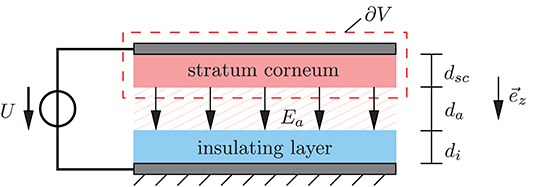
Figure 2. Parallel-plate capacitor model; the dashed line marks the integration domain used for calculation of the electrostatic force.
The electrostatic force onto the upper part of the capacitive system consisting of the upper plate and the stratum corneum (see Figure 2) can be calculated from the general definition, that is, by integration of the Maxwell stress tensor T over the surface of the enclosed volume:
where denotes the electric field, I is the unit tensor of second order and ε the absolute permittivity. In our simple capacitive system, the only contribution to the electrostatic force on the upper part comes from the electric field of the air gap , which points in the z-direction and thus perpendicular to the relevant surface. Therefore, only the zz-component of the Maxwell stress tensor is required to calculate the electrostatic force according to Equation (15), which leads to
From the continuity of the normal component of the electrical displacement at the interfaces between stratum corneum and air as well as air and insulating layer of the screen, the following relationships hold:
where the abbreviations “sc” and “i” stand for “stratum corneum” and “insulating layer,” respectively. In addition, the voltage between the plates can be determined from the line integration of the electrical field, which leads to the following result:
Herein, dsc, da, and di represent the thicknesses of the stratum corneum, air gap and insulating layer of the screen. From Equations (18) and (19) the electric field in the air gap can be determined and after substituting the result into Equation (17) the magnitude of the electrostatic force yields:
where we have introduced the relative permittivities εr,sc, εr,a, and εr,i as well as the permittivity of free space ε0 on the right side. After dividing Equation (20) by the plate area, the electrostatic force per unit area is found:
Analogous to the work of adhesion that comes from the van der Waals forces, the work of electro-adhesion was introduced by Popov and Heß (2018). It represents the required work per unit area to separate the plates and can be calculated by:
Let us briefly take a closer look at the limiting case of “direct contact,” i.e., a disappearing air gap. The corresponding electrostatic force results from Equation (20) taking into account da = 0:
If we make use of the usual estimation εr,a ≈ 1, then Equation (23) exactly agrees with the formula proposed by Strong and Troxel (1970) in their pioneering work:
It should be noted that alternative approaches to Equations (24) and (20) were proposed by Kaczmarek et al. (2006) and Vodlak et al. (2016), which are supported by several authors (see e.g., Radivojevic et al., 2012; Giraud et al., 2013; Vezzoli et al., 2014; Liu G. et al., 2018). It goes without saying that these approaches can alternatively be integrated into the new model. Nevertheless, this work makes use of Equations (20–22). It is assumed that there is always an air gap even in the in-contact state, which includes not only the interstitial spaces between the ridges but also non-contacting areas on smaller length scales resulting from roughness. It is well-known that even the ridges themselves are far away from being smooth. They are punctuated by many concave shaped sweat pores openings. According to measurements by Liu et al. (2013), the number of sweat ducts considerably varies between subjects and lies between 300 and 1,000 per cm2. Therefore, some authors have recently introduced the junction area as a measure of the real contact area (Dzidek et al., 2016). Current purely theoretical investigations using mean-field models based on multiscale contact mechanics take even smaller scales into account which results in a further, significant decrease of the predicted real contact area. A ratio is given by Ayyildiz et al. (2018) for instance.
Concept of an equivalent air gap
As mentioned above, the real contact area is made up of various micro-asperity contacts and is generally much smaller than the apparent or ridge contact area. This results in a non-uniform interfacial air gap between the surfaces of the stratum corneum and insulating screen layer. As part of a macroscopic model, we want to capture the whole influence of the non-uniform air gap on the electrostatic force by introducing an equivalent air gap of constant thickness. It is worth noting that the real non-uniform interfacial air gap and thus also the thickness of the equivalent air gap strongly depends on both the normal force and the applied voltage. If the real non-uniform air gap corresponding to a given normal force and voltage were known, the equivalent air gap would be obtained from:
where da,eq denotes the equivalent air gap. Unfortunately, it is impossible to determine the non-uniform air gap. However, the equivalent air gap concept can be used in another way. Some scientists calculate the equivalent air gap from accessible experimental data on the frictional force in electroadhesive contacts to incorporate it into a suitable substitute model. For example, Guo et al. (2019) measured the friction force of the finger sliding on a 3M touchscreen at different normal forces but under a fixed apparent contact area. From their experimental results they estimated the electrostatic force, which increased significantly with increasing normal force. The authors explain this effect through an existing (equivalent) air gap between the fingertip and screen, whose thickness decreases with increasing normal force by a power function. At 150 V peak-to-peak voltage, the thickness decreased from 2.5 to 1.5 micrometers when the normal force has been increased from 0.5 N to 4.5 N. Nakamura and Yamamoto (2016) have proposed a multi-user visuo-haptic system, which integrates an additional rubber-like pad between the fingertip and touchscreen surface that has a surface-insulated electrode on its bottom. By means of an electrically activated and insulated screen electrode an electrostatic force acts on the pad and is then transferred to the fingertip placed on the pad. The electrostatic component to the friction force obtained from measurements showed different behavior at small and large voltages. Thus, they included an equivalent air gap in their parallel-plate capacitor model that varies between 0 and 6 micrometers depending on the applied voltage. We would also like to highlight the work of Shultz et al. (2015), who succeeded in unifying the DC based Johnson Rahbek and AC based electrovibration force models. They clearly show that Coulombic attraction force across the very small interfacial air gap is the origin of both. An alternative possibility is to calculate the thickness of the air gap from knowledge of the measured capacitance, as implemented by Nakamura and Yamamoto (2017) or Shultz et al. (2018). In summary, all the above-mentioned works predict a thickness of the equivalent gap in the order of a few micrometers. Keeping this order of magnitude, the equivalent air gap as a function of the normal force is used in section Sliding Friction to fit the friction force resulting from the tangential contact model onto experimental data.
Application to Fingerpad in Contact With Capacitive Screen
In the following, the developed theoretical principles are applied to the normal contact between the fingerpad and the screen under electrovibration. Therefore, the solution of the corresponding non-adhesive contact is required, whereby “non-adhesive” means that the voltage is turned off. Adhesion due to van der Waals forces are excluded. One critical point must be discussed in advance. The compliance method is based on the principle of superposition, hence its application is restricted to linear elasticity. Human skin, however, shows non-linear material behavior and the contact between finger and screen is associated with large deformations. Although these non-linearities indicate a breakdown of superposition, Lin and Chen (2006) have demonstrated that under comparatively weak adhesion the compliance method can still be applied in the large-deformation regime assuming non-linear elastic materials. In this case, the adhesive part of the solution to be superposed must be understood as a linear perturbation of the non-linear non-adhesive one. Hence, the applicability of this so-called large-deformation JKR (LDJKR) theory is linked to the validity of the assumption:
By using the finite element method, Lin and Chen (2006) studied two adhesive contact problems involving hyperelastic material: the contact between a hyperelastic hemisphere and a smooth rigid substrate as well as the contact between a smooth rigid spherical indenter and a hyperelastic half-space. In both cases they checked the accuracy of Equation (26) which actually coincided with the simulation results. Further applications of the LDJKR to Neo-hookean layers can be found in the work by Lin et al. (2008). Without further proof, but based on the above explanations, it is assumed that the compliance method can be applied to the contact between the fingerpad and the screen, too.
The solution of the non-adhesive normal contact between the index finger and screen is required as input for the compliance method. For this purpose, experimental results from accessible literature are used. We focus on the range of small normal forces between 0 and 2 N, which are relevant regarding electrovibration. Although some reported experimental data in literature vary significantly, there is general consensus that both the dependence of the apparent contact area A0 and the ridge contact area AR on the normal force can be fitted to power functions according to Equation (5). Given exponents corresponding to the apparent contact area in the low force regime range between 0.36 and 0.42 and those corresponding to the ridge contact area range between 0.42 and 0.58 (Warman and Ennos, 2009; van Kuilenburg et al., 2013a; Lin et al., 2015; Dzidek et al., 2017; Liu X. et al., 2018). Taking into account that the relationship between area and load depends on many things like the fingerpad inclination angle, measurement methods (ink printing or optical method), environmental conditions (temperature and humidity) and individual properties of the finger (influenced by age and gender of subjects) the differences in exponents are still relatively small. Soneda and Nakano (2010) determined slightly higher exponents from measurements with an optical method, 0.52 for the apparent and 0.68 for the ridge contact area, but they consider a different range of forces lying between 0.1 and 5 N. For further investigations, values from the work by Dzidek et al. (2017) are taken, since it also provides the required relationship between the contact area and indentation depth according to Equation (6).
Approach Based on Apparent Contact Area
The measurement results of Dzidek et al. (2017) stem from the left index finger of a 27-year-old female subject. With regard to the power functions according to Equations (5) and (6), at a finger inclination angle of 30 degrees relative to the smooth countersurface, the following parameters were determined:
where the subscript “0” signifies parameters corresponding to the apparent contact area. After inserting these parameters into Equations (9) and (10), the corresponding solution of the electroadhesive contact is found. In Figure 3, the apparent contact area as a function of the normal force is plotted for different values of the work of electroadhesion. Curves over the entire loading range are shown on the left, whereas the plot on the right gives an enlarged view of the pull-off region associated with negative loads. The solid black lines represent the original power-law fits to the experimental measurements by Dzidek et al. (2017). The other two solid lines illustrate the solutions under electroadhesion corresponding to different values of the work of adhesion, w = 0.132 J/m2 and w = 0.532 J/m2. Both are calculated from Equation (22) considering a voltage of 200 V but in one case a realistic equivalent air gap thickness of 1 μm is assumed whereas the other one takes into account unlikely complete contact, characterized by an disappearing equivalent air gap. At first glance, especially if one assumes a moderate air gap thickness, the change in the contact area when switching on the voltage appears so small that one tends to neglect it. However, it can be clearly seen from Figure 3 on the right that this is not permitted for the range of very small normal forces (combined with higher voltages), which is definitely still of interest for electrovibration. The curve associated with w = 0.132 J/m2 predicts a pull-off force of 6.74 mN. In addition, the pure voltage-induced contact (no external normal force is applied) creates a contact area of 24.14 mm2. Unfortunately, to the best of the authors' knowledge, no experimental data are available in this interesting range.
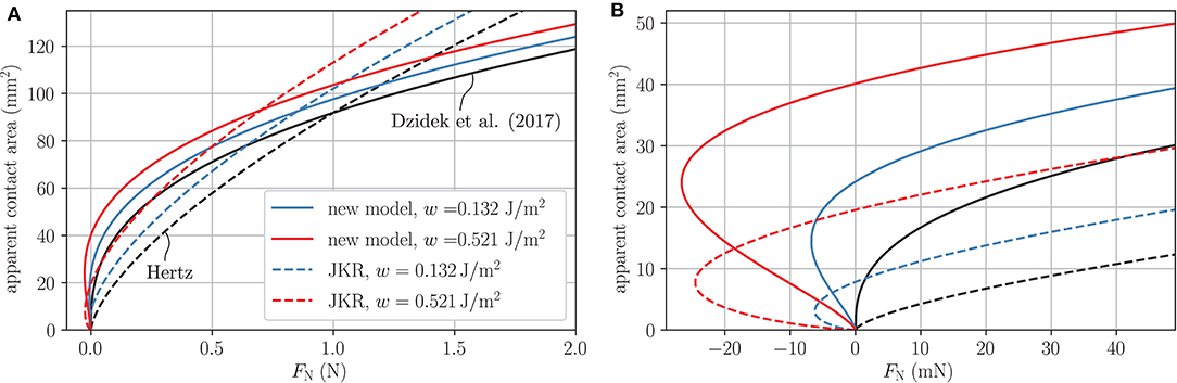
Figure 3. Apparent contact area as a function of normal load for different works of electroadhesion; black curves represent the non-adhesive solution; (A) Plot over the whole loading range; (B) Enlarged view of the pull-off region associated with negative loads.
The percentage change in the apparent contact area decreases with increasing normal force. At a normal force of 0.5 N, the change is still around 9 %. Nevertheless, in recent measurements by Sirin et al. (2019b) for characteristic normal forces of 0.5 N, 1 N, and 2 N, no significant difference was observed between the (initial) apparent contact areas with and without electrovibration. Thus, it can be assumed that switching on the voltage only results in an enlargement of the ridge contact area. This is the main reason why we decided to develop a model based on the ridge contact area instead of the apparent one.
Approach Based on Ridge Contact Area
Under the assumption that the LDJKR theory remains valid for applications to contact problems involving non-linear elastic human skin material, we were able to derive a solution for the electro-adhesive contact between the finger and the screen. It was tacitly assumed that the apparent contact area is compact and approximately circular. The applicability of the LDJKR theory to the ridge contact area requires an additional, very strict assumption. As previously mentioned, each contact area configuration under electroadhesion must be the same as that of the corresponding non-adhesive contact loaded by an appropriately chosen higher normal force (Ciavarella, 2018; Popov, 2018). This condition is definitely not fulfilled here! However, since more suitable simple methods do not exist, the compliance method is used once again to obtain a (rough) approximate solution.
In the following, we proceed in exactly the same way as in the last section. First, the parameters for the power functions are taken from the work by Dzidek et al. (2017).
where the subscript “R” indicates parameters corresponding to the ridge contact area. Subsequently, these parameters are inserted into Equations (9) and (10) which yields the solution under electroadhesion. The ridge contact area as a function of the normal force is plotted in Figure 4, again distinguishing between the three characteristic cases: non-adhesive contact, contact under electroadhesion taking into account an equivalent airgap of 1 μm as well as complete contact associated with a vanishing equivalent air gap.
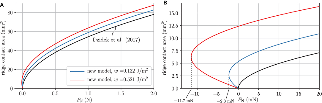
Figure 4. Ridge contact area as a function of normal load for different works of electroadhesion; black curves represent the non-adhesive solution; (A) Plot over the whole loading range; (B) Enlarged view of the pull-off region associated with negative loads.
In the latter two electroadhesive cases, pull-off forces of 2.3 and 11.7 mN are obtained, as illustrated by Figure 4B. The change in the ridge contact area at a normal force of 0.5 N reads 11.2% for an air gap of one micron and 23.8% for complete contact.
As already stated, there appears to be no experimental data in the literature to evaluate the quality of our model and adjust the equivalent air gap thickness from it. In this context, however, we would like to point out that models based on Hertz or the original JKR theory assuming a parabolic profile and a constant equivalent elastic modulus cannot map the apparent or ridge contact area as a function of the normal force correctly. To show this, the apparent contact area for the cases of Hertz and original JKR [see Equation (13)] are included in Figure 3. The effective radius was estimated with R* ≈ 1 cm and an effective elastic modulus of E* ≈ 47.4 kPa is chosen such that the apparent contact areas for the non-adhesive normal contact agree at FN = 1 N. The values for the work of (electro-)adhesion are chosen as for the new model. The Hertzian prediction differs significantly from the experimentally verified non-adhesive curve by Dzidek et al. (2017). Of course, these large differences are inherited in the JKR cases. At most, Hertz based models that take into account an equivalent effective elastic modulus that varies with the contact area (or indentation depth) would be qualified for modeling (van Kuilenburg et al., 2013a,b). Nevertheless, such models would still have to be suitably expanded to include the effect of electroadhesion.
Tangential Contact With Electroadhesion
A suitable, macroscopic model for mapping the electroadhesive frictional contact between the fingerpad and screen should fulfill three main characteristics:
I. It should be based on a model for normal contact under electroadhesion.
II. It must be able to reproduce the experimentally observed contact area reduction caused by the frictional force in the state of full slip.
III. It requires a macroscopic approach for the frictional force.
Regardless of these specifications, the quality of a model can only be ensured by experimental verification of all relevant correlations. To meet the first point, the normal contact model based on the ridge contact area presented in section Application to Fingerpad in Contact with Capacitive Screen is applied. It is essentially described by Equation (9) with exponents mR = 0.52 and nR = 1.41 originating from the experiments by Dzidek et al. (2017). The occurring work of electroadhesion w is defined by Equation (22).
To satisfy requirement II, most current studies exploit adhesion theories based on fracture mechanics concepts. For this reason, section Tangential Contact under Full Stick assumption—Peeling starts with a discussion about peeling. However, by means of simulations with a two-dimensional FE model of the fingertip in section Transition from Stick to Slip—the Evolution of Contact Area in the Non-adhesive Case, it is shown, that the area reduction is mainly caused by large deformations of the non-linear elastic material around the distal phalanx. Therefore, in consistence with the FE results and available experimental investigations by Sahli et al. (2018) the area reduction is incorporated empirically [see Equation (43)].
On the defined macroscopic scale, a pressure-controlled friction law is assumed in section Sliding Friction. In connection with the specific parameter optimization, this leads to a good agreement of the friction force and the friction coefficient with experimental data. However, the incorporation of extended approaches consisting of both a pressure-based and an adhesion-based term is in principle possible.
Tangential Contact Under Full Stick Assumption—Peeling
Most current theoretical studies on tangential contacts of soft materials try to explain the experimentally observed contact area reduction by fracture mechanics concepts. They focus on the adhesive contact between elastically similar materials loaded by a small tangential force that does not cause any slip in the contact area. Under this full-stick condition all material points within the contact area undergo the same tangential displacement δT with respect to points remote from the contact area. In this case, the compliance method can easily be extended by including corresponding energetic terms to the elastic strain energy as well as the mechanical potential energy of the external load. This results in an energy release rate given by:
where ST: = dFT/dδT denotes the tangential contact stiffness. After setting the energy release rate G equal to the work of (electro)adhesion w the general solution of the (no-slip) tangential contact under electroadhesion is obtained. Note, that the applicability of the extended compliance method is neither restricted to homogeneous materials nor to the half-space approximation or circular contact areas, but linear material behavior is required. In principle, the same requirements apply as for the theory of pure normal contact with adhesion. In this context, Equation (29) represents a novelty to the best of the authors' knowledge. Unfortunately, its applicability to non-linear elastic materials is constrained by very small tangential forces. Since the tangential stiffness of the contact does not emerge from any literature, a direct extension of the promising results for the normal contact with adhesion from section Application to Fingerpad in Contact With Capacitive Screen is not readily possible. In order to discuss the influence of the tangential force on the apparent contact area between the finger and the screen, the (homogenized) Hertzian-based contact model is used as a rough approximation instead. In this case the normal and tangential contact stiffness read (Popov et al., 2019).
By substituting the results of Equation (30) into Equation (29) and taking into account G = w, the apparent contact area as a function of the applied external forces is determined after some rearranging
According to Equation (31), the contact area decreases with increasing tangential force. Since the tangential force causes a mode I separation, this effect is termed “peeling.” Stable peeling proceeds until the critical tangential force FT,c is reached:
Note, that the expressions given in Equations (31) and (32) are equivalent to results of the pioneering work by Savkoor and Briggs (1977). As a rough estimate, the effective values for the radius, R* ≈ 1 cm, and the elastic modulus, E* ≈ 47.4 kPa, that are already used in section Approach Based on Ridge Contact Area are again used and the work of electroadhesion is taken as w = 0.132 J/m2 which corresponds to an equivalent air gap of one micron (see section Approach Based on Apparent Contact Area). Since the insulating layer of the screen is much stiffer than the soft finger material the effective elastic modulus is determined by the latter. In addition, incompressible skin material is assumed to meet the requirement of elastic similarity which prescribes G*/E* = 2/3. The apparent contact area as a function of the applied tangential force for different normal forces is illustrated in Figure 5. The values of the tangential forces at the end points of the curves correspond to the critical tangential forces according to Equation (32).
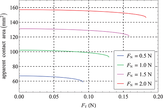
Figure 5. Apparent contact area as a function of tangential load for different normal forces.
The reduction is clearly too small compared to experimental results by Sirin et al. (2019b). The theory also significantly underpredicts the maximum tangential load, i.e., the reduction of the contact area cannot be explained satisfactorily by means of this simplified theory. It could be remedied by appropriate modeling of the transition regime from peeling to complete sliding. Peeling itself represents only the initial stage of static friction. However, the transition regime itself has not been sufficiently understood until today and is beyond of the scope of this work. Instead, we would like to briefly address another option. In the model by Savkoor and Briggs (1977), the work of adhesion is assumed to be constant throughout the loading. However, from experimental results it is known, that the work of adhesion can significantly increase under combined normal and tangential loading. In this case, the constant work of adhesion for pure mode I loading w must be replaced by a mode-mixity-dependent :
where KI and KII denote the mode I and mode II stress intensity factors. It is common to use one of the three phenomenological functions for interface cracks proposed by Hutchinson and Suo (1991) as normalized interfacial toughness function f(ψ). They include only one empirical parameter which can be used to fit onto measurement results (Johnson, 1996; Waters and Guduru, 2010; Papangelo and Ciavarella, 2019). The same procedure could now be followed to improve the adaptation of the model to the measurement data concerning the apparent area reduction in the electroadhesive tangential contact between the finger and the screen. However, this should be deliberately avoided because the main cause for the reduction of the contact area when applying a tangential force is not adhesion! In the next section, this claim is supported by a simplified FEM calculation for a non-adhesive, tangential contact between a finger and smooth rigid plate, taking into account non-linear elastic material behavior. Note, that very recently a similar finding concerning a smooth contact between a soft cylindrical cap and a rigid plate was made by Mergel et al. (2020). They have shown that the contact length decreased under tangential shear even in the absence of adhesion.
Transition From Stick to Slip—the Evolution of Contact Area in the Non-adhesive Case
Several experimental studies report a significant decrease of apparent contact area when a tangential force is applied to the fingerpad under constant normal loading (Delhaye et al., 2014; Sirin et al., 2019b). This area reduction is already significant without electroadhesion, but is further increased under the influence of electroadhesion (Sirin et al., 2019b). Contrary to the peeling mechanism described in the previous section, this much larger reduction is accompanied by the development of local slip in the contact zone. It is further shown that the contact area does not shrink uniformly, but that primarily the length parallel to the tangential loading is reduced. Sahli et al. (2018) studied the apparent contact area as well as the real contact area and found that both reduce with the same reduction mechanisms. The investigated real contact area is of the order of magnitude of the ridge contact area discussed in section Approach Based on Ridge Contact Area.
As already stressed in the previous section, we believe that adhesion is not the decisive factor for the area reduction. It is known from experiments that the measured macroscopic adhesion for the contact of skin and dry glass is negligibly small (Wang et al., 2020) and cannot explain the significant reduction without any influence of electroadhesive forces.
Delhaye et al. (2014) make the non-linear elastic properties of skin responsible for the area reduction. The originally coiled collagen fibers in the skin become oriented and straightened in the direction of stress. This results in a significant stiffening under a tangential force. However, we believe that the large deformation of the finger and the complex layered structure contribute to the observed effect as well. Without further investigation, this assumption was already expressed by Wang et al. (2020).
We conducted a simple two-dimensional plane strain finite element study using ABAQUS to study the origin of the area reduction further. Following Wu et al. (2006), a cross-section of the finger depicted in Figure 6A is modeled with layers for skin, subcutaneous tissue, bone and nail in non-adhesive contact with a rigid smooth plate. The friction properties of the contact are modeled by the local form of the Amontons-Coulomb law. Both, geometrical and material parameters, were taken from Wu et al. (2006). Skin and subcutaneous tissue are modeled as hyperelastic materials using the Ogden model (Ogden, 1973). In contrast to commonly used hyperelastic models such as the Mooney-Rivlin or the Neo-Hookean model, the Ogden model may accurately describe the skin stiffening behavior (Shergold et al., 2006).
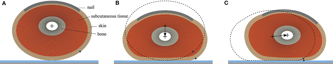
Figure 6. Layered finite element model of the cross-section of the fingerpad. (A) Undeformed mesh. (B) Deformed mesh prior to tangential displacement with FN = 0.8 N/mm. (C) Deformed mesh in the state of full slip with the coefficient of friction μ = 0.35 and FN = 0.8 N/mm.
In a first step, the modeled cross-section is pressed against the rigid plate by applying a normal force per unit width to the inner bone layer (see Figure 6B). Then, the cross-section is moved tangentially while keeping the applied normal force constant until the whole contact length is slipping (see Figure 6C). At the onset of the tangential displacement, the skin layer behaves similar to a fluid filled membrane. It is generally much stiffer than the subcutaneous tissue and begins to “roll” around the bone (notice the marked node in Figure 6 that moves into contact). As the finger is further displaced, the soft tissues begin to stiffen and slip propagates from the trailing edge. At the onset of full slip (Figure 6C), the geometry has drastically changed due to the large deformations and the contact length is decreased significantly.
The evolution of the contact length from the onset of tangential loading to the onset of full slip is shown in Figure 7. The total reduction of contact length is small for low normal forces and increases for higher normal forces. Owing to the finite geometry, the contact length and the observed reduction are not increasing at the same rate for higher normal forces. The contact length during tangential loading can be described by a simple quadratic function of the tangential force per unit width,
where L0 is the initial contact length prior to tangential loading. Fits of this form are included as dashed gray lines in Figure 7A, where ξ is a function of the normal force per unit width with .
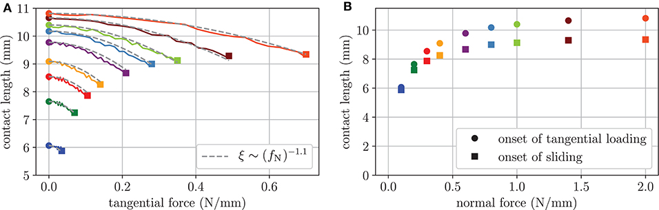
Figure 7. Evolution of the contact length parallel to the tangential displacement of the two-dimensional finite element model with the coefficient of friction μ = 0.35. (A) contact length against tangential force per unit width. The dashed gray lines are fits in the form of Equation (34). (B) Contact length against normal force per unit width prior to tangential loading and at the onset of sliding.
The conducted finite element analysis supports the assumption that the observed contact area reduction under tangential loading is not caused by adhesion, but a result of large deformation and strain stiffening behavior of skin and subcutaneous tissue. However, due to the plane strain assumption and the negligence of fingerpad ridges, it is difficult to compare the results to experimental data quantitatively. Collecting the tissue layers of the epidermis and dermis in a homogeneous “skin” layer with smeared properties is a further limitation. Thus, in the present form, the model can only be used as a rough estimate. Nevertheless, similar to Equation (34) for the contact length and in accordance with Sahli et al. (2018) an empirical formula for the reduction of the ridge contact area is employed in section Sliding Friction.
Sliding Friction
Now the question arises which friction law is suitable for mapping the sliding contact between the finger and the screen under electroadhesion on the defined macroscopic scale. For this purpose the well-known approach of Bowden and Tabor is chosen as a starting point:
where τ denotes the interfacial shear strength and Areal is the “real” contact area. Usually, for many polymeric materials as well as human skin, the interfacial shear strength itself is composed of a constant intrinsic term τ0 and a second term that is linearly dependent on the mean contact pressure p (Briscoe and Tabor, 1975; Adams et al., 2007).
where is constant. Substituting Equation (36) in Equation (35) yields:
Depending on whether the friction force according to Equation (37) is dominated by the first or second term, the friction is called adhesion-controlled or pressure-controlled, respectively. Note, that in this context adhesion refers to the rupture of interfacial junctions and has nothing to do with our electroadhesion. In order to include electroadhesion in the approach above, it is assumed that electroadhesion only contributes to the normal contact pressure associated with an increased contact area. Then, the following extension replaces Equation (36):
and from Equation (35) the friction force results in:
From a microscopic or atomic point of view, the real contact area is made up of the sum of the micro-asperity contact areas and thus only a very small fraction of the apparent contact area. Associated with this small-scale multi-asperity contact model, values of the shear strength are typically in the order of a few Megapascal (Persson, 2018). From experimental results by Adams et al. (2007), the intrinsic interfacial shear strength between wet human skin and glass lies in the range of some Kilopascal which indicates that the assumed real contact area is of the same order as the ridge contact area. By using this information, the real contact area can be replaced by the ridge contact area:
From our macroscopic point of view, Equation (40) shall represent the central law of sliding friction under electroadhesion. In the following, focus is only on pressure-controlled friction which might be a strong assumption. An investigation considering the complete approach in Equation (40) should be part of a future work. Under the pressure-controlled assumption, Equation (40) reduces to
where has been replaced by the “real” friction coefficient μ0, as it was termed by Derjaguin (1934). Equation (41) represents the generalized Amontons-Coulomb law of friction, which is often used to model friction within problems of electrovibration (see e.g., Kaczmarek et al., 2006; Shultz et al., 2018; Heß and Popov, 2019). From Equation (41) the “apparent” friction coefficient reads:
Note, that the electroadhesive force per unit area σel in the sliding friction law according to Equation (41) is given by Equation (21). For pure normal contact under electroadhesion, the ridge contact area (in the following renamed to AR,0) is calculated from the model introduced in section Approach Based on Ridge Contact Area described by Equation (9) with exponents mR = 0.52 and nR = 1.41. For the sliding contact, however, we further must account for the area reduction described in section Transition From Stick to Slip—the Evolution of Contact Area in the Non-adhesive Case that depends on the tangential force. Similar to the empirical formula (34) that we found for the contact length of the finite element model, the empirical quadratic law proposed by Sahli et al. (2018) for the ridge contact area:
is employed, where AR, 0 is the ridge contact area prior to tangential loading and the parameter η is a function of the normal force of the form:
where the constant c2 is yet to be determined. Here, the exponent -1 is adopted, which is experimentally determined by Sahli et al. (2018) for the real contact area. It should be noted that in the current work of Basdogan et al. (2020) an analogous empirical approach was adopted for the apparent contact area, but η was assumed to be constant. Inserting Equation (43) into Equation (41) and solving for the tangential force yields:
In the following, the proposed model for sliding friction is verified by comparison to the experimental data presented by Sirin et al. (2019a). In this experimental study, the tangential force of a sliding fingerpad on a 3 M touchscreen was measured for different voltages applied to the conducting layer of the touchscreen. The experimenter was trained to keep the normal force at a constant value during the measurements. Unfortunately, neither apparent nor ridge contact area were measured during this series of experiments.
In order to obtain adequate relations for the non-adhesive ridge area in the form of the power-law functions (5, 6), we again make use of the functions proposed by Dzidek et al. (2017) that are fitted to measurements of the finger of a female experimenter. In Figure 8, Dzidek's functions are compared to the measured apparent contact areas of four different subjects by Delhaye et al. (2014) and the averaged measurements by Sirin et al. (2019b). Obviously, Dzidek's original relations underestimate the apparent contact area of the other studies significantly. Under the assumption that the exponents remain the same, a scaling of the power-law functions for the apparent contact area as well as the ridge area was performed to obtain a better agreement with the experimental results. The exponents of the best fits for each subject vary considerably, but the exponent provided by Dzidek et al. represents a good compromise. The parameters of the adjusted relations for the non-adhesive ridge contact area are listed in Table 1.
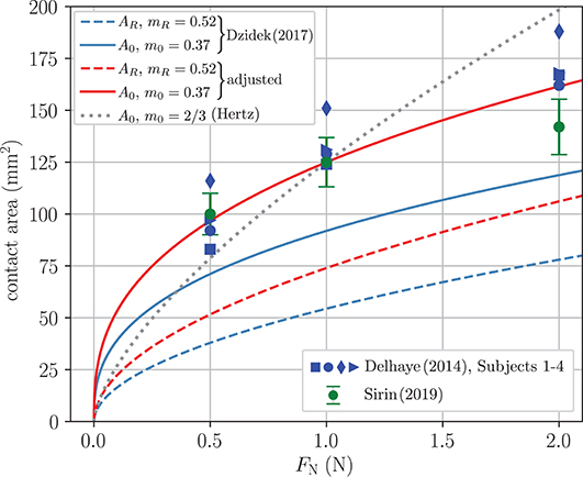
Figure 8. Contact area in terms of the normal force. The symbols represent measured apparent contact areas given by Delhaye et al. (2014) and Sirin et al. (2019b) and the solid lines are power-law fits for the apparent contact area. The dashed lines are power-law relations for the ridge contact area.
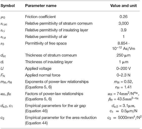
Table 1. Parameters used for the model of sliding friction.
It should be noted that many authors simply employ the Hertzian relation with the exponent to model the non-adhesive normal contact. A corresponding fit is included in Figure 8. As expected, the Hertzian relation is inadequate owing to the finite size and the complex layered structure of the finger.
With the non-adhesive ridge contact area, the ridge contact area for the electroadhesive contact prior to tangential loading AR, 0 can be determined by inversion of Equation (9). The work of adhesion w is given in Equation (22). The electromechanical parameters needed for the electroadhesive force per unit area σel and the work of adhesion are listed in Table 1. Most parameters are taken from Sirin et al. (2019a) and the thickness of the stratum corneum for the fingerpad in contact is taken from Lee et al. (2020).
The concept of the equivalent air gap is discussed in section Theoretical Background. For the model of sliding friction, it is assumed that the thickness of the equivalent air gap da is a linearly decreasing function of the normal force,
where the parameters da,0 and c1 are yet to be determined.
The three unknown parameters for the area reduction and the air gap and in Equations (44) and (46), respectively, are found by fitting the model to the experimental results. However, the curve fitting is closely confined by the requirement that both, the area reduction and the air gap, remain within realistic ranges known from experiments.
The fitted parameters are included in Table 1 and the ridge contact area reduction as well as the air gap thickness are shown in Figures 9A,B, respectively. Prior to tangential loading, the ridge contact area at constant normal loading increases up to 20% due to the electroadhesion. At the onset of sliding, the ridge contact area is reduced significantly for high initial contact areas and only marginally for smaller initial contact areas. Furthermore, the reduction is increased significantly for high voltages. Sirin et al. (2019b) investigated the reduction of apparent contact area without electroadhesion and with electroadhesion at 100 V applied voltage. They report an average reduction of 8% without and 13% with electrovibration at an applied normal force of 1 N as well as 15 and 20%, respectively, at 2 N. Our model predicts a similar ridge area reduction of approximately 5% without electrovibration and 10% with 100 V at 1 N as well as 12 and 19% at 2 N. It is valid to compare these results, because the apparent contact area and the real contact area follow analogous reduction mechanisms and the relative reduction is very similar for both (Sahli et al., 2018). It should further be noted that Sirin et al. (2019b) measured a higher coefficient of friction presumably due to the oil they needed for image analysis. Thus, we expect a slightly increased relative area reduction for this study.
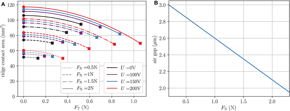
Figure 9. (A) Modeled reduction of the ridge area according to Equation (43) due to tangential loading. Circles mark the ridge area prior to tangential loading and squares mark the onset of sliding. (B) Air gap against normal force according to Equation (46).
The thickness of the equivalent airgap shown in Figure 9B reduces from 2.85 μm at 0.5 N to 2.1 μm at 2 N. The thickness is thus in the range reported by other studies (see also Section Concept of an equivalent air gap) and agrees with <0.5 μm difference especially well with the predictions by Guo et al. (2019).
Figure 10 shows the tangential force of the sliding fingerpad in terms of the applied normal force. The symbols represent the measurements by Sirin et al. (2019a) and the solid lines the results of the model described above. Especially for applied voltages above 50 V, the tangential force is increased significantly in the whole range of applied normal forces. Apart from small differences for low voltages, the model is in very good agreement with the experimental results. The apparent coefficient of friction (COF) μ = FT/FN depicted in Figure 11 reaches a constant value for normal forces larger than 1 N. In this range, the apparent COF increases almost linearly with the applied voltage and is more than doubled for 200 V. Again, the model is in very good agreement.
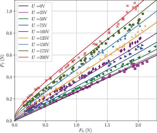
Figure 10. Model predictions (lines) and experimental results (symbols) of Sirin et al. (2019a) of tangential force against normal force for voltages of 25–200 V.
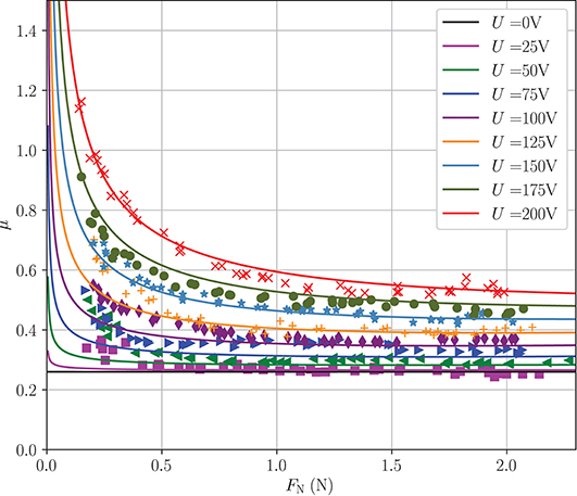
Figure 11. Model predictions and experimental results by Sirin et al. (2019a) of the apparent coefficient of friction against normal force for voltages of 25–200 V.
The apparent COF increases significantly with decreasing normal forces in the range of normal forces lower than 0.5 N. This behavior is characteristic for adhesive contacts. Here, the model predictions are lower than the experimental results for voltages smaller than 150 V. We believe these deviations can be at least partly explained by classical van der Waals adhesion: Sirin et al. (2019a) also measured the tangential force for a sliding fingerpad without electroadhesion and show that the curves for 25 and 0 V are not distinguishable. Thus, mainly classical adhesion or capillary bridges are responsible for the small increase in apparent COF for 25 V. However, we believe the effect of electroadhesion is predominant in most cases justifying the negligence of classical van der Waals adhesion. Other inaccuracies may be found in the power-law relations for the ridge contact area at low normal forces. In this range very little experimental data is available and contact area has a very steep slope making it prone for errors.
Sirin et al. (2019a) also describe a model of sliding friction based on multiscale contact mechanics which agrees reasonably well with the experimental results. In this model, the real contact area is described by microasperities of skin in contact and is several orders of magnitude smaller than the apparent contact area. However, our much simpler macroscopic modeling approach based on the ridge contact area and the concept of an equivalent air gap is equally suited and yields, in fact, even better agreement with the experimental results.
Conclusion and Discussion
A new macroscopic model for sliding friction of a fingerpad over a smooth surface under electroadhesion has been developed. One of the cornerstones of the modeling is the application of Shull's compliance method to large deformations. In this way, a solution was first obtained for pure normal contact under electroadhesion, which in particular includes the dependence of the ridge contact area on the normal force as well as the applied voltage. To account for the experimentally observed reduction of the ridge contact area during transition from stick to slip, an empirical formula is employed according to which the area reduction is proportional to the square of the applied tangential force. This is consistent with experiments by Sahli et al. (2018) as well as results of our finite element simulations. After incorporating the developed solution for the pure normal contact and the empirical formula of area reduction into a pressure-based approach for the frictional force, the new macroscopic model for voltage-induced friction has been found. A comparison with recent experimental data has shown that the model adequately predicts both the frictional force and the coefficient of friction over the entire range of relevant voltages and applied normal forces.
A further important outcome with regard to the reduction of the contact area results from our finite element study with a two-dimensional model of the fingerpad, where skin and subcutaneous tissue were considered as hyperelastic materials using the Ogden model to accurately describe skin stiffening. Although the simulations are restricted to non-adhesive tangential contacts, they show a significant reduction of the contact area, which is mainly caused by large deformations of the non-linear elastic material around the distal phalanx. This result challenges numerous recent studies on tangential contacts of soft materials that attempt to describe the experimentally observed area reduction caused by the frictional force using adhesion theories based on fracture mechanics concepts. Obviously, adhesion plays only a minor role for the area reduction. Hence, completely new theoretical approaches are required to model this effect in a physically meaningful way.
One uncertainty in the proposed modeling concerns the calculated ridge contact area under normal loading with electroadhesion. Since the influence of electroadhesion on the ridge area has not yet been investigated, the corresponding results obtained are currently still purely theoretical. Appropriate measurements should be part of a future task. The experimental results could as well be used to quantify the equivalent air gap more precisely. In addition, contributions to adhesion due to van der Waals forces have so far been completely ignored in the model. The same applies to capillary forces, although it is known that they cause a further increase of the coefficient of friction at low normal loads under wet conditions (Morales-Hurtado et al., 2017).
Furthermore, it should be noted that the proposed model requires the solution of the non-adhesive normal contact a priori. Although it is irrelevant for the application of Shull's method, whether this solution originates from experiments (like here), a simulation with the finite element method or something similar, the claim should be to find a suitable theoretical model also for the ridge contact area as a function of the normal force.
Data Availability Statement
All datasets generated for this study are included in the article/supplementary material.
Author Contributions
All authors listed have made a substantial, direct and intellectual contribution to the work, and approved it for publication.
Conflict of Interest
The authors declare that the research was conducted in the absence of any commercial or financial relationships that could be construed as a potential conflict of interest.
Acknowledgments
We are grateful to Prof. Dr. Cagatay Basdogan and his colleagues for many valuable discussions during the international conference on Contact Mechanics (Berlin, Oct. 2019) and for providing us with their experimental data.
References
Adams, M. J., Briscoe, B. J., and Johnson, S. A. (2007). Friction and lubrication of human skin. Tribol. Lett. 26, 239–253. doi: 10.1007/s11249-007-9206-0
Argatov, I. I., and Borodich, F. M. (2020). A macro model for electroadhesive contact of a soft finger with a touchscreen. IEEE Trans. Haptics 13, 504–510. doi: 10.1109/toh.2020.2969628
Ayyildiz, M., Scaraggi, M., Sirin, O., Basdogan, C., and Persson, B. N. J. (2018). Contact mechanics between the human finger and a touchscreen under electroadhesion. Proc. Natl. Acad. Sci. U.S.A. 115, 12668–12673. doi: 10.1073/pnas.1811750115
Basdogan, C., Sormoli, M. R., and Sirin, O. (2020). Modeling sliding friction between human finger and touchscreen under electroadhesion. IEEE Trans. Haptics 13, 511-521. doi: 10.1109/toh.2020.2989221
Briscoe, B. J., and Tabor, D. (1975). The effect of pressure on the frictional properties of polymers. Wear 34, 29–38. doi: 10.1016/0043-1648(75)90306-3
Ciavarella, M. (2018). An approximate JKR solution for a general contact, including rough contacts. J. Mech. Phys. Solids 209–218. doi: 10.1016/j.jmps.2018.03.005
Delhaye, B., Lefèvre, P., and Thonnard, J. L. (2014). Dynamics of fingertip contact during the onset of tangential slip. J. R Soc. Interf. 11:20140698. doi: 10.1098/rsif.2014.0698
Derjaguin, B. (1934). Molekulartheorie der äußeren Reibung. Zeitschrift für Physik 88, 661–675. doi: 10.1007/BF01333114
Derler, S., and Gerhardt, L. C. (2012). Tribology of skin: review and analysis of experimental results for the friction coefficient of human skin. Tribol. Lett. 45, 1–27. doi: 10.1007/s11249-011-9854-y
Dzidek, B., Bochereau, S., Johnson, S., Hayward, V., and Adams, M. (2016). “Frictional dynamics of finger pads are governed by four length-scales and two time-scales,” in IEEE Haptics Symposium (HAPTICS) (Philadelphia, PA), 161–166. doi: 10.1109/HAPTICS.2016.7463171
Dzidek, B. M., Adams, M. J., Andrews, J. W., Zhang, Z., and Johnson, S. A. (2017). Contact mechanics of the human finger pad under compressive loads. J. R Soc. Interf. 14:127. doi: 10.1098/rsif.2016.0935
Giraud, F., Amberg, M., and Lemaire-Semail, B. (2013). “Merging two tactile stimulation principles: electrovibration and squeeze film effect.” in 2013 World Haptics Conference (WHC), 199–203. doi: 10.1109/WHC.2013.6548408
Guo, X., Zhang, Y., Wang, D., Lu, L., Jiao, J., and Xu, W. (2019). The effect of applied normal force on the electrovibration. IEEE Trans. Haptics 12, 571–580. doi: 10.1109/TOH.2019.2897768
Heß, M., and Popov, V. L. (2019). Voltage-induced friction with application to electrovibration. Lubricants 7:102. doi: 10.3390/lubricants7120102
Hutchinson, J. W., and Suo, Z. (1991). Mixed mode cracking in layered materials. Adv. Appl. Mech. 29, 63–191. doi: 10.1016/S0065-2156(08)70164-9
Johnson, K. L. (1996). Continuum mechanics modeling of adhesion and friction. Langmuir 12, 4510–4513. doi: 10.1021/la950889a
Johnson, K. L., Kendall, K., and Roberts, A. D. (1971). Surface energy and the contact of elastic solids. Proc. R. Soc. Lond. A 324, 301–313. doi: 10.1098/rspa.1971.0141
Kaczmarek, K. A., Nammi, K., Agarwal, A. K., Tyler, M. E., Haase, S. J., and Beebe, D. J. (2006). Polarity effect in electrovibration for tactile display. IEEE Trans. Biomed. Eng. 53, 2047–2054. doi: 10.1109/TBME.2006.881804
Lee, Z. S., Maiti, R., Carré, M. J., and Lewis, R. (2020). Morphology of a human finger pad during sliding against a grooved plate: a pilot study. Biotribology 21:100114. doi: 10.1016/j.biotri.2019.100114
Lin, H. T., Hong, T. F., and Li, W. L. (2015). Grip performance affected by water-induced wrinkling of fingers. Tribol. Lett. 58:38. doi: 10.1007/s11249-015-0515-4
Lin, Y. Y., Chang, C. F., and Lee, W. T. (2008). Effects of thickness on the largely-deformed JKR (Johnson-Kendall-Roberts) test of soft elastic layers. Int. J. Solids Struct. 45, 2220–2232. doi: 10.1016/j.ijsolstr.2007.11.025
Lin, Y. Y., and Chen, H. Y. (2006). Effect of large deformation and material nonlinearity on the JKR (Johnson–Kendall–Roberts) test of soft elastic materials. J. Polymer Sci. Part B Polymer Phys. 44, 2912–2922. doi: 10.1002/polb.20914
Liu, G., Sun, X., Wang, D., Liu, Y., and Zhang, Y. (2018). Effect of electrostatic tactile feedback on accuracy and efficiency of pan gestures on touch screens. IEEE Trans. Haptics 11, 51–60. doi: 10.1109/toh.2017.2742514
Liu, X., Carré, M. J., Zhang, Q., Lu, Z., Matcher, S. J., and Lewis, R. (2018). Measuring contact area in a sliding human finger-pad contact. Skin Res. Technol. 24, 31–44. doi: 10.1111/srt.12387
Liu, X., Lu, Z., Lewis, R., Carré, M. J., and Matcher, S. J. (2013). Feasibility of using optical coherence tomography to study the influence of skin structure on finger friction. Tribol. Int. 63, 34–44. doi: 10.1016/j.triboint.2012.08.020
Mergel, J. C., Scheibert, J., and Sauer, R. A. (2020). Contact with coupled adhesion and friction: computational framework, applications, and new insights. arXiv [Preprint]. arXiv:2001.06833.
Meyer, D. J., Peshkin, M. A., and Colgate, J. E. (2013). “Fingertip friction modulation due to electrostatic attraction,” in IEEE World Haptics Conference (WHC) (Daejeon), 43–48. doi: 10.1109/WHC.2013.6548382
Morales-Hurtado, M., de Vries, E. G., Peppelman, M., Zeng, X., van Erp, P. E. J., and van der Heide, E. (2017). On the role of adhesive forces in the tribo-mechanical performance of ex vivo human skin. Tribol. Int. 107, 25–32. doi: 10.1016/j.triboint.2016.11.006
Nakamura, T., and Yamamoto, A. (2016). A multi-user surface visuo-haptic display using electrostatic friction modulation and capacitive-type position sensing. IEEE Trans. Haptics 9, 311–322. doi: 10.1109/TOH.2016.2556660
Nakamura, T., and Yamamoto, A. (2017). Modeling and control of electroadhesion force in DC voltage. ROBOMECH J. 4:18. doi: 10.1186/s40648-017-0085-3
Ogden, R. W. (1973). Large deformation isotropic elasticity - on the correlation of theory and experiment for incompressible rubberlike solids. Rubber Chem. Technol. 46, 398–416. doi: 10.5254/1.3542910
Papangelo, A., and Ciavarella, M. (2019). On mixed-mode fracture mechanics models for contact area reduction under shear load in soft materials. J. Mech. Phys. Solids 124, 159–171. doi: 10.1016/j.jmps.2018.10.011
Persson, B. N. J. (2018). The dependency of adhesion and friction on electrostatic attraction. J. Chem. Phys. 148:144701. doi: 10.1063/1.5024038
Popov, V. L. (2018). Solution of adhesive contact problem on the basis of the known solution for non-adhesive one. Facta Univ. Series Mech. Eng. 16, 93–98. doi: 10.22190/FUME180105009P
Popov, V. L., and Heß, M. (2018). Voltage induced friction in a contact of a finger and a touchscreen with a thin dielectric coating. arXiv [Preprint]. arXiv:1805.08714.
Popov, V. L., Heß, M., and Willert, E. (2019). Handbook of Contact Mechanics, Exact Solutions of Axisymmetric Contact Problems. Berlin Heidelberg: Springer. doi: 10.1007/978-3-662-58709-6
Radivojevic, Z., Beecher, P., Bower, C., Cotton, D., Haque, S., Andrew, P., et al. (2012). Programmable electrostatic surface for tactile perceptions. SID Symp. Digest Tech. Papers 43, 407–410. doi: 10.1002/j.2168-0159.2012.tb05802.x
Sahli, R., Pallares, G., Ducottet, C., Ben Ali, I. E., Al Akhrass, S., Guibert, M., et al. (2018). Evolution of real contact area under shear and the value of static friction of soft materials. Proc. Natl. Acade. Sci. U.S.A. 115, 471–476. doi: 10.1073/pnas.1706434115
Savkoor, A. R., and Briggs, G. A. D. (1977). Effect of tangential force on the contact of elastic solids in adhesion. Proc. R Soc. London Ser. A 356, 103–114. doi: 10.1098/rspa.1977.0123
Shergold, O. A., Fleck, N. A., and Radford, D. (2006). The uniaxial stress versus strain response of pig skin and silicone rubber at low and high strain rates. Int. J. Impact Eng. 32, 1384–1402. doi: 10.1016/j.ijimpeng.2004.11.010
Shull, K. R. (2002). Contact mechanics and the adhesion of soft solids. Mater. Sci. Eng. R Rep. 36, 1–45. doi: 10.1016/S0927-796X(01)00039-0
Shull, K. R., Ahn, D., Chen, W., Flanigan, C. M., and Crosby, A. J. (1998). Axisymmetric adhesion tests of soft materials. Macromol. Chem. Phys. 199, 489–511. doi: 10.1002/(SICI)1521-3935(19980401)199:4<489::AID-MACP489>3.0.CO;2-A
Shultz, C., Peshkin, M., and Colgate, J. E. (2018). The application of tactile, audible, and ultrasonic forces to human fingertips using broadband electroadhesion. IEEE Trans. Haptics 11, 279–290. doi: 10.1109/TOH.2018.2793867
Shultz, C. D., Peshkin, M. A., and Colgate, J. E. (2015). “Surface haptics via electroadhesion: expanding electrovibration with Johnsen and Rahbek,” in IEEE World Haptics Conference (WHC) (Evanston, IL), 57–62. doi: 10.1109/WHC.2015.7177691
Sirin, O., Ayyildiz, M., Persson, B. N. J., and Basdogan, C. (2019a). Electroadhesion with application to touchscreens. Soft Matter. 15, 1758–1775. doi: 10.1039/C8SM02420K
Sirin, O., Barrea, A., Lefèvre, P., Thonnard, J. L., and Basdogan, C. (2019b). Fingerpad contact evolution under electrovibration. J. R Soc. Interf. 16:156. doi: 10.1098/rsif.2019.0166
Soneda, T., and Nakano, K. (2010). Investigation of vibrotactile sensation of human fingerpads by observation of contact zones. Tribol. Int. 43, 210–217. doi: 10.1016/j.triboint.2009.05.016
Strong, R. M., and Troxel, D. E. (1970). An electrotactile display. IEEE Trans. Man Machine Syst. 11, 72–79. doi: 10.1109/TMMS.1970.299965
van Kuilenburg, J., Masen, M., van Der Heide, A. E. (2013a). The role of the skin microrelief in the contact behaviour of human skin: contact between the human finger and regular surface textures. Tribol. Int. 65, 81–90. doi: 10.1016/j.triboint.2012.11.024
van Kuilenburg, J., Masen, M., and van der Heide, A. E. (2013b). Contact modelling of human skin: What value to use for the modulus of elasticity? Proc. Inst. Mech. Eng. Part J. J. Eng. Tribol. 227, 349–361. doi: 10.1177/1350650112463307
van Kuilenburg, J., Masen, M., and van der Heide, A. E. (2015). A review of fingerpad contact mechanics and friction and how this affects tactile perception. Proc. Inst. Mech. Eng. Part J J. Eng. Tribol. 229, 243–258. doi: 10.1177/1350650113504908
Vardar, Y., Güçlü, B., and Basdogan, C. (2017). Effect of waveform on tactile perception by electrovibration displayed on touch screens. IEEE Trans. Haptics 10, 488–499. doi: 10.1109/TOH.2017.2704603
Vezzoli, E., Amberg, M., Giraud, F., and Lemaire-Semail, B. (2014). “Electrovibration modeling analysis,” in Haptics: Neuroscience, Devices, Modeling, and Applications. EuroHaptics 2014. Lecture Notes in Computer Science, Vol. 8619, eds M. Auvray, and C. Duriez (Berlin; Heidelberg: Springer). doi: 10.1007/978-3-662-44196-1_45
Vodlak, T., Vidrih, Z., Vezzoli, E., Lemaire-Semail, B., and Peric, D. (2016). Multi-physics modelling and experimental validation of electrovibration based haptic devices. Biotribology 8, 12–25. doi: 10.1016/j.biotri.2016.09.001
Wang, J., Tiwari, A., Sivebaek, I., and Persson, B. N. J. (2020). Sphere and cylinder contact mechanics during slip. arXiv [Preprint]. arXiv:2002.02226. doi: 10.1016/j.jmps.2020.104094
Warman, P. H., and Ennos, A. R. (2009). Fingerprints are unlikely to increase the friction of primate fingerpads. J. Exp. Biol. 212, 2016–2022. doi: 10.1242/jeb.028977
Waters, J. F., and Guduru, P. R. (2010). Mode-mixity-dependent adhesive contact of a sphere on a plane surface. Proc. R. Soc. A Math. Phys. Eng. Sci. 466, 1303–1325. doi: 10.1098/rspa.2009.0461
Keywords: friction, adhesion, electrovibration, surface haptics, finite element method—FEM, compliance method, hyperelastic material
Citation: Heß M and Forsbach F (2020) Macroscopic Modeling of Fingerpad Friction Under Electroadhesion: Possibilities and Limitations. Front. Mech. Eng. 6:567386. doi: 10.3389/fmech.2020.567386
Received: 29 May 2020; Accepted: 20 August 2020;
Published: 21 October 2020.
Edited by:
Irina Goryacheva, Institute for Problems in Mechanics (RAS), RussiaReviewed by:
Cagatay Basdogan, Koç University, TurkeyEmile Van Der Heide, University of Twente, Netherlands
Copyright © 2020 Heß and Forsbach. This is an open-access article distributed under the terms of the Creative Commons Attribution License (CC BY). The use, distribution or reproduction in other forums is permitted, provided the original author(s) and the copyright owner(s) are credited and that the original publication in this journal is cited, in accordance with accepted academic practice. No use, distribution or reproduction is permitted which does not comply with these terms.
*Correspondence: Markus Heß, markus.hess@tu-berlin.de