Sustainable Compliant Physical Interaction in a Biped-Wheeled Wearable Machine
 Gaspare Trono
 Angelo Nicolì
  Giovanni Gerardo Muscolo
- DIMEAS-Department of Mechanical and Aerospace Engineering, Politecnico di Torino, Torino, Italy
This paper deals with the problem of the physical human-machine interaction in biped-wheeled exoskeletons and underlines how the symbiosis between humans and machines may increase sustainability. Few exoskeletons in the world are designed with wheels, but the evolution of wearable machines in industries and the convenience of using wheels, underline the importance of the novel research sector of biped-wheeled exoskeletons. This paper shows the functional design and simulation of a novel biped-wheeled wearable machine, including sustainable compliant physical interaction with the subject on board. In particular, the multibody model of the proposed machine is studied and simulated with the subject model on board, including human-machine compliant interactions. The classical human walking cycle is implemented in the machine, varying the speed and the joint compliance of the subject on board and comparing the torque and power output of the motors of the biped-wheeled exoskeleton. The results of this study underline how the joint compliance of the subject on board of the biped-wheeled exoskeleton may influence the efficiency and sustainability of the biped-wheeled wearable machine.
1. Introduction
The Sustainable Development Goals of the 2030 Agenda of the United Nations member states define lines for a novel humanity. The technology must be oriented to be in line with the planned goals. In Lee et al. (2016), sustainability for the wearable technology is presented, underlining how this is a crucial point for the future of wearable systems.
Wearable robots and exoskeletons have been included in our society for helping people. Many studies have been performed on exoskeletons for working applications. In Panero et al. (2019, 2020a,b), the influence of the hinge positioning for optimizing exoskeletons and reducing human efforts are studied. In these papers, the human effort reduction is obtained using an upper body exoskeleton to help the subject to lift goods.
Many steps must be performed for increasing the sustainability of the upper and lower body exoskeletons. For the sustainability of the complete human-machine system, the subject should be in symbiosis with the exoskeleton. The efficiency of the exoskeleton is important for the human safety, reducing efforts and increasing performances. However, the human must learn to use the machine sustainably in order to reduce his efforts and motor consumptions and to have a more sustainable machine.
Many exoskeletons have been developed for lower limb applications. Many examples may be found in literature and on the market: BLEEX (Zoss et al., 2006), the Berkeley lower extremity exoskeleton; the Body Extender (Marcheschi et al., 2011), an advanced wearable robot conceived to augment human strength; some commercial devices, such as RewalkTM (Awad et al., 2020), EksoTM (Read et al., 2020), IndegoTM(Arora and McIntyre, 2020), and many others.
In the novel vision of sustainability for exoskeletons, what is the simple element that may increase the human performances? The authors think that the wheels (though not only them) rather than the feet could be one of the elements that may be included in the exoskeletons to increase sustainability.
How many exoskeletons are conceived with wheels? To the best of authors' knowledge, not many exoskeletons are conceived with wheels until now. In de Carvalho (2018), a lower limb exoskeleton is presented in which the subject is sitting like in a wheelchair. In Onishi et al. (2003), a leg-supporting unit is proposed; however, the hoist unit has big dimensions. In Borisoff and Rafer (2017), a wheeled chair able to pass from a sitting to standing position is presented. In Song et al. (2019), another mechanism for the same application is presented. In Ma et al. (2017, 2018), an interesting exoskeleton with wheels is presented, but it may not be used by people with a complete absence of mobility and only with partial mobility. In particular, the motion of the lower limb exoskeleton presented in Ma et al. (2017, 2018), is permitted thanks to the crutches moved by the upper part of the body. In these two works (Ma et al., 2017, 2018), rollers are included in the lower part of the feet of the exoskeleton.
The approach of including wheels instead of feet in the exoskeletons is the same as the one used in humanoid robotics research, where some difficulties underlined in biped locomotion may be bypassed by including wheels instead of feet. In literature, prototypes of legged robots with wheels have recently been developed (Hitachi, 2010; BostonDynamics, 2017, 2019). For this purpose, some researchers have presented Rollo, a biped-flexible wheeled robot (Muscolo and Recchiuto, 2017). This paper was underlined as one of the “Notable articles on Biped Robots” (only six papers have this honour today) (IJHR, 2020). After these results, other studies on modelling and compliance in legged robots (Muscolo et al., 2017; Maiorino and Muscolo, 2020; Spadaro and Muscolo, 2020) have permitted the evolution of Rollo in a novel biped-wheeled wearable robot (or biped-wheeled exoskeleton). Different aspects of this novel device are analysed in other works, including human comfort (Zoccali and Muscolo, 2021), the multibody model design (Nicoli, 2020), and the first prototype in a reduced scale (Loschi, 2020).
In this paper, a simulation of the multibody models of the biped-wheeled wearable machine and the subject on board are performed, modifying the compliance of the joints of the subject. Thanks to this approach, very interesting results have been obtained and are presented. In particular, the output of the torque and power of the motors of the machine are compared, moving the biped-wheeled exoskeleton with two different speeds and with different compliance in the joints of the subject.
The paper is structured as follows: section 2 presents the used biped-wheeled exoskeleton model; section 3 shows the compliance used for the model of the subject; section 4 presents the multibody models of the exoskeleton and the subject; section 5 shows the control architecture used to simulate the model behavior; section 6 contains the results and discussions. The paper ends with conclusion.
2. Biped-Wheeled Exoskeleton Model
The sketch of the biped-wheeled exoskeleton is shown in Figure 1. The subject is fixed to the exoskeleton by his trunk (fixed to the base for the trunk) and feet (fixed to the base for the feet). The main purpose of this exoskeleton and its novelty are underlined by its capability to completely support humans without muscular activities (e.g., Amyotrophic Lateral Sclerosis's patients or people with a Complete Locked-In Syndrome). The exoskeleton is able to move a human subject (conceived as a dummy), which is not able to give an active contribution to the robot motion. However, the novel biped-wheeled exoskeleton may be used by a human without disabilities.
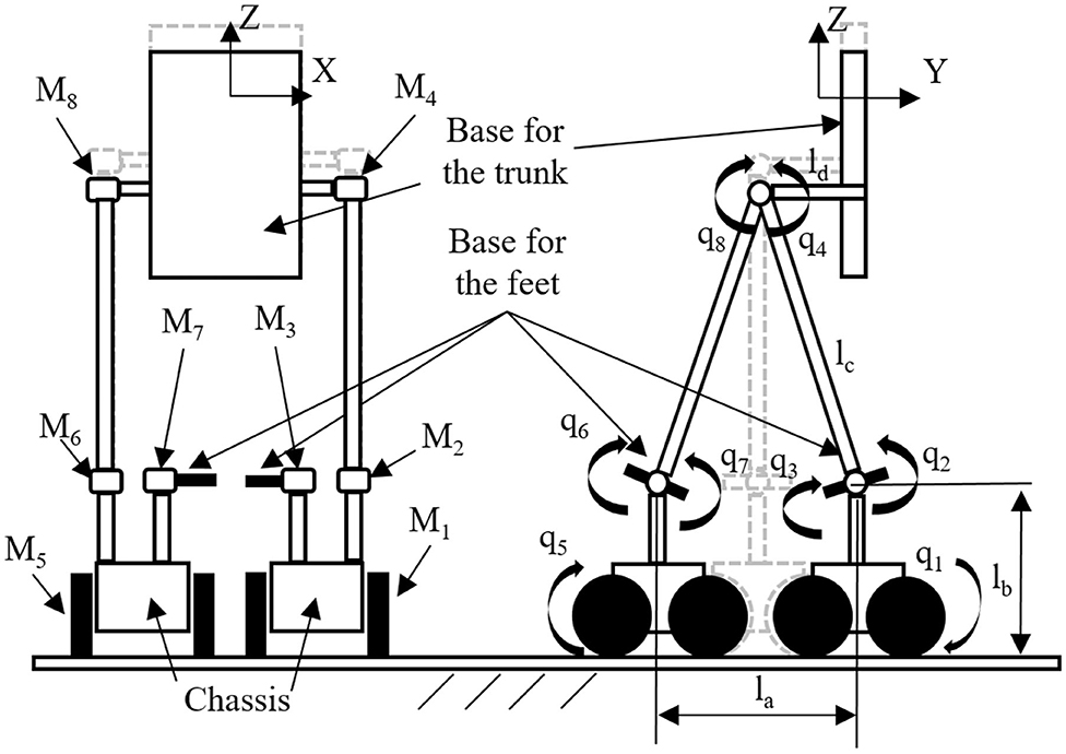
Figure 1. Sketch of the biped-wheeled exoskeleton (or biped-wheeled wearable machine).
The exoskeleton is composed of eight motors (Ms) in the revolute joints of the wearable machine:
• Two for the motion of the wheels (M1, M5);
• two for the motion of the ankle joints of the exoskeleton (M2, M6);
• Two for the motion of the ankle joints of the human subject (M3, M7);
• Two to control the motion of the human trunk (M4, M8).
Figure 1 shows some characteristics of the biped-wheeled exoskeleton model. The original kinematic chain is composed by eight DoFs (see Figure 1, right), one in each revolute joint (q1, q2, q3, q4, q5, q6, q7, and q8). The biped-wheeled exoskeleton can be moved in the environment with two different configurations and with the eight wheels always in contact with the ground:
1. Alternating the motion of the chassis of each foot in order to reproduce the walking cycle of the subject on board;
2. Moving each chassis in order to obtain a motion similar to a segway in which each leg remains parallel to the other one and the joints of one leg have axes that are coaxial to the respective joints of the other one.
In the first configuration, M1 and M5 may be synchronized with the steps performed by the human's feet in a classical walking cycle. The distance (la) of each chassis (see Figure 1 on the right) from the other one represents the step performed, and it may be used as input to define the motion of the whole system. Simple geometrical considerations allow us to underline that, in the first configuration, six of the eight DoFs are linearly independent from the other ones. In particular, from Figure 1 (right) it can be noted that one leg is the mirror of the other one and that q2 = q6 and the following equation are satisfied by geometrical conditions:
In conclusion, in the first configuration, the kinematic chain has six linearly independent DoFs (q1, q3, q4, q5, q7, and q8), and only six motors are then requested for the motion (M1, M3, M4, M5, M7, and M8). However, to maintain the equilibrium in the second configuration, all the eight motors must be activated. The first configuration is the most difficult to analyze, and it represents the novelty of the proposed machine, allowing a biped wheeled motion. For these reasons, in this paper, only the first configuration will be analyzed.
3. Compliance in the Subject
The main purpose of the exoskeleton is to permit to the subject to walk at different speeds, remaining on board of the machine. In particular, this machine is useful for subjects with muscular disabilities, because it allows them to move muscles in a passive mode and to be able to do rehabilitation exercises. However, the same machine may be used by people without disabilities as personal vehicles for daily use or for sport.
Human gait can be divided mainly into two phases (Tu and Lee, 2010):
• The stance phase, which begins when a foot touches the ground and ends when the same foot leaves the ground.
• The swing phase, which begins when a foot leaves the ground and ends when the same foot touches the ground.
During the cycle, it is possible to define single support and double support zones:
• In the single support, the load is on the support leg, while the other leg is swinging.
• In double support, the load is on the two legs.
Two other important parameters of walk are the stride length and the step length. Stride length is the distance between the heel strike of the same foot, while step length is the distance between heel strike of one foot and the heel strike of the other foot during walking.
In a first approximation of the walking on a plane, three joints for each leg may be considered: the ankle, knee, and hip joints. The principal movements of the ankle are dorsiflexion and plantarflexion on the sagittal plane and inversion and eversion on the frontal plane. The hip joint is responsible for the equilibrium of the upper part of the body. The knee joint movements are extension, flexion, and lateral and medial rotation (these last two only when the knee is flexed).
Some studies have underlined how each joint of the human has a stiffness function of the walking cycle (Shamaei et al., 2013; Sartori et al., 2015). In this paper, the authors used the peak values for each joint (hip, knee, and ankle), calculated in Shamaei et al. (2013) and Sartori et al. (2015), and implemented them on the model of the subject, obtaining a more realistic motion.
4. Multibody Models: Exoskeleton and Subject
Figure 2 shows the multibody model of the exoskeleton machine and the subject on board, designed using the dimensions of a standard man (age: 30; height: 1,720 mm; weight: 70 kg) (Maiorino and Muscolo, 2020).
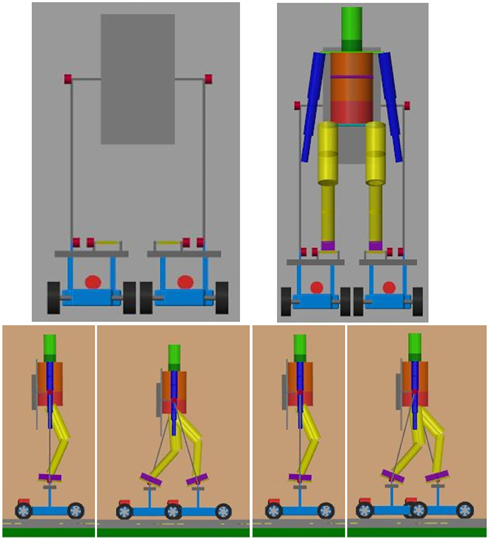
Figure 2. Multibody model of the biped-wheeled exoskeleton and the subject on board on it.
Figure 2 shows how the human is positioned on the machine. In particular, the subject is fixed to the machine by the feet and the trunk. Some walking steps are presented in the same figure. The complete multibody model is composed of three subsystems: the external environment, the subject, and the exoskeleton.
The environment is composed of a planar surface, and it defines the contact forces between the wheels and the ground.
The subject subsystem is obtained using the dimensions of the standard man available in literature (Maiorino and Muscolo, 2020); it is composed of 19 rigid bodies and 33 joints. Each body part (hands, arms, legs, trunk, neck, feet, and head) has been designed with the same dimensions, weights, and center of mass positions of the standard man, as shown in Maiorino and Muscolo (2020), giving as input the total height (1,720 mm) and weight (70 kg) of the subject and validating their interaction in a multiphysic environment. The subject multibody model is attached to the exoskeleton at three points: the trunk (and head) and the two feet. In our preliminary tasks, the arms are not fixed. The starting angles of the hip, knee, and ankle joints are away for the anthropomorphic borders in order to simulate the behavior without external constraints. However, the anthropomorphic displacements of the joints are free to move (no joints constraints are implemented on the subject). In particular, we used the following starting values (reported here in absolute values) with respect to the stance position: hip = 20°, knee = 40°, and ankle = 20°.
The biped-wheeled exoskeleton subsystem has 44 different rigid bodies and eight actuated joints. The functional design of the presented version of the exoskeleton is obtained with the intent to reduce (as soon as possible) the weight in the upper part of the exoskeleton; this allows us to avoid falls. The wheels of each chassis must remain always in contact with the ground and have the great advantage of being able to increase the weight in the lower part of the biped-wheeled wearable machine. On the contrary, in literature and on the market, the weight of the classical exoskeletons must be always reduced because the walk is performed alternating the contact of the foot with the ground. In a preliminary functional design, a total weight of the biped-wheeled exoskeleton has been obtained: 78 kg in which 56 kg constitute the lower part. However, this is only a first model and may be different from the exoskeleton that will be realized in future steps. As can be seen from Figure 2, the biped-wheeled exoskeleton is designed around a subject with a height of 1,720 mm and a weight of 70 kg. In this first functional design, the biped-wheeled exoskeleton and the subject have a total weight of 148 kg. For each motor, a weight of about 2 kg has been estimated, and all weights of the structure have a reference to some available commercial products. The base of the trunk has a weight of 7 kg and each chassis of 10 kg. As explained above, this is a first step for the biped-wheeled exoskeleton, and it will be optimized in future steps.
5. Control Architecture
Figure 3 shows the general control architecture implemented on the multibody model. The input of the control system are the reference speeds (m/s) of the left and right chassis, which are integrated in time to obtain their positions ql (m) and qr (m). The human takes the first step with his left foot and then continues with the stance and swing phases. All the other actuators are synchronized to simulate the movement of the human subject during walking.
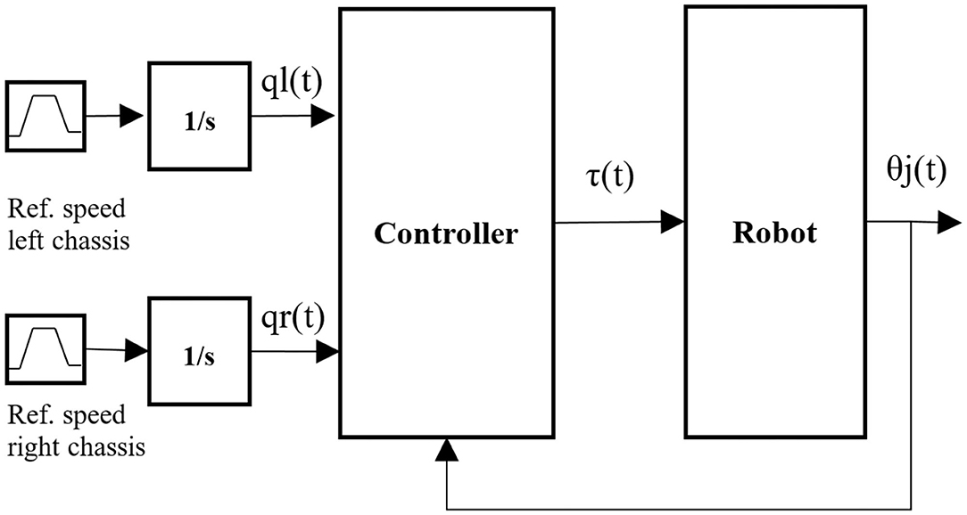
Figure 3. General control architecture.
In order to obtain the position of the other joints, the step length definition is required during simulation; it is defined as the difference in the position of the axes of the motors M1 and M5 (see la in Figure 1 on the right). To ensure the trunk remains vertical during locomotion, the motor M4 (M8) must compensate for the motion of the motor M2 (M6). The block “Robot” of the Figure 3 contains the models of the exoskeleton, the subject, and the external environment. Each motor is controlled using a Proportional-Integral-Derivative (PID) controller with position in feedback to guarantee the stability and tracking of the trajectory. The PID receives as input the error, obtained by the difference between the reference position and the real position of the joint, and it provides the torque as the output. Figure 4 shows the control system in a single joint.
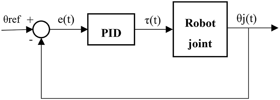
Figure 4. Control system of a single joint.
The output of the PID is influenced by four factors (Kp, Ki, Kd, N) to be set in order to obtain the desired response as shown in Table 1. The parameters are obtained in order to reduce the instability of the whole system and to have a local stability in the equilibrium points of each joint motor.
Kp is the proportional gain; e(t) is the error; Ki is the integrative gain; Kd is the derivative gain; and N is the derivative filter coefficient. The parameters chosen for the PIDs change depending on the joint to be actuated.
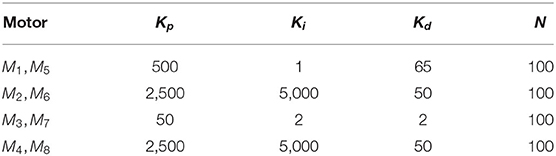
Table 1. PID Parameters.
6. Results and Discussion
6.1. Planned Tasks
The main purpose of this work is to analyze and simulate the physical interaction between the subject and the biped-wheeled wearable machine in two different conditions (tasks) in joint stiffness in humans:
• Task 1 represents a subject with zero stiffness in the lower limb joints (ankle, knee, and hip).
• Task 2 represents a subject with the following values of stiffness in the lower limb joints (peak values considered, Shamaei et al., 2013; Sartori et al., 2015): ankle stiffness = 5.9 Nm/deg; knee stiffness = 4.8 Nm/deg; hip stiffness = 5.25 Nm/deg.
Another important simulation performed is the trajectory tracking because it is an essential requirement for the applications of an exoskeleton. In the following simulation (and for each task), each chassis is moved along y axis (see Figure 1) alternatively with two different speeds of 0.73 m/s (speed 1) and 1.4 m/s (speed 2) for about 10 m.
6.2. Trajectory Tracking
Figure 5 shows the input positions used for each chassis (left and right) at speed 1 (0.73 m/s). Figure 6 shows the position (x, y, and z, see Figure 1) of the base for the trunk (seat position) during motion. From this figure it may be seen how the inclusion of the stiffness in the subject (task 2) allows to move the machine in a correct position, avoiding the asymmetry in motion during the walking cycle. In particular, in task1, it can be noted how the x value position is different from zero, by 7–15 s; this means that the exoskeleton is moved not only in the y direction (for many reasons related to the vibration, friction, etc.). In task 2, the presence of compliance in the subject allows us to maintain the x around zero, and the same final position of y is obtained in a reduced time.
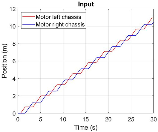
Figure 5. Speed 1 (0.73 m/s): Input on the left and right chassis.
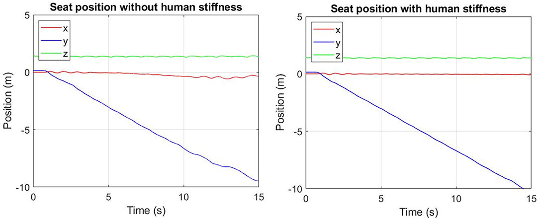
Figure 6. Speed 1 (0.73 m/s): Position of the base for trunk in task 1 (left) and task 2 (right).
The following figures show the results of the simulation of the left side of the exoskeleton. The graphs on the right side have the same behavior. In the joint of M3, some differences between the two tasks (1 and 2) are underlined and can be seen in following section.
Figure 7 shows the angular displacements (radiant) of the three joints of the left leg (q2, q3, and q4) where the three motors M2, M3, and M4 are implemented, respectively, and the robot is moved with the speed 1 and with the trajectory shown in Figure 5. Figure 7 compares the results obtained with task 1 (on the left) and 2 (on the right). It can be seen from the graphs that in task 2, the errors between the reference and simulated real positions of M2 and M4 are reduced respect to the graphs shown in task 1. Moreover, the peaks are also reduced. M3 and M4 are the two motors that interact directly with the subject and the machine for the left side (such as the M7 and M8 for the right side), but M3 for the left side (such as the M7 for the right side) is more influenced by human stiffness, as can be seen from the graphs. The errors between the reference and simulated real positions in task 2 are greater than the errors in task 1 for M3; in task 2, the simulated real position is higher than in task 1. These first results underline that the stiffness in the subject may be an important point for the sustainable development of the motion of the subject with a wearable system.
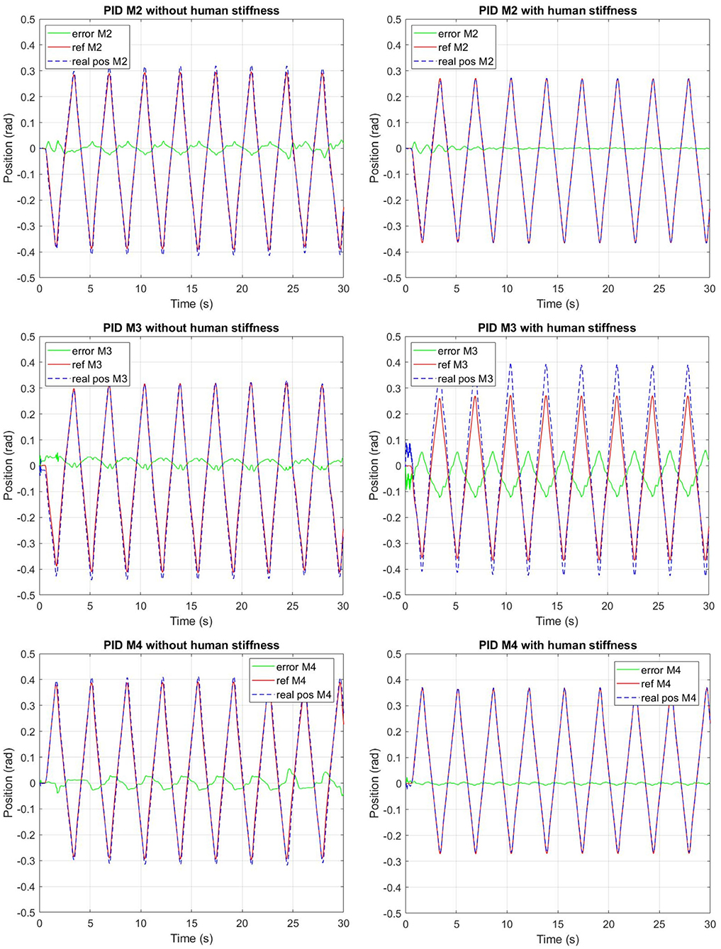
Figure 7. Speed 1 (0.73 m/s): Reference position (solid line), simulated real position (dotted line), and error (green line) without human stiffness (task 1-left) and with human stiffness (task 2-right) for the motors M2, M3, and M4.
Table 2 shows the maximum absolute values of the tracking error of the Figure 5. Regarding M1, M2, and M4, the current position follows the reference input in the same way in both tasks, but smaller errors are noted for task 2 than task 1 (e1, e2, e4). However, a big difference in error can be seen in the behavior of the motor M3. In task 2, the joint with M3 presents bigger dorsiflexion and plantarflexion than the expected ones, and the error e3 exhibits a different behavior compared to e1, e2, and e4 for the reasons described above.
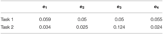
Table 2. Speed 1 (0.73 m/s): Maximum absolute values of the tracking error.
6.3. Torque and Power
The comparisons between task 1 and task 2 for the torque and power requested by the four motors (M1, M2, M3, and M4) of the left side of the biped-wheeled wearable machine are shown respectively in Figures 8, 9 for the speed 1 (0.73 m/s).
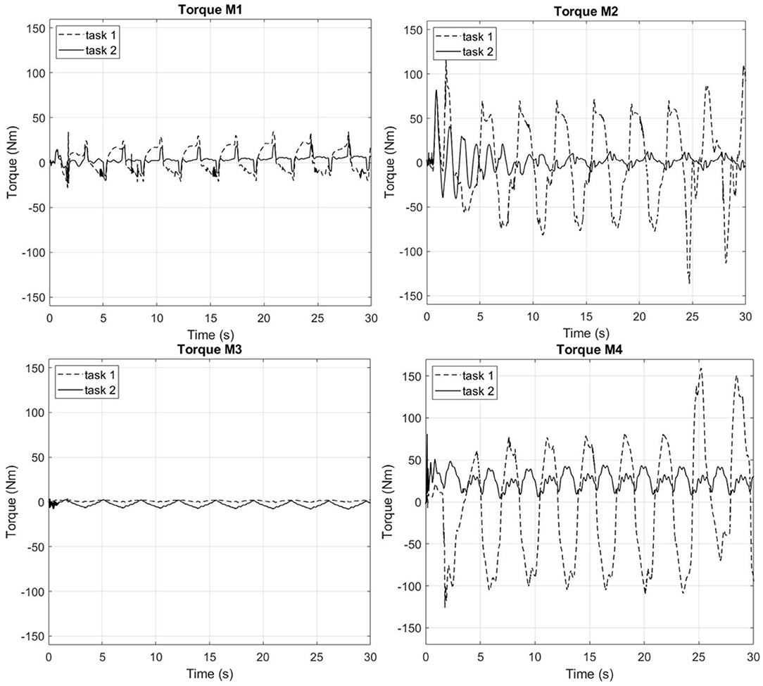
Figure 8. Speed 1 (0.73 m/s): Torque (Nm) in the joints of the left leg of the biped-wheeled exoskeleton in task 1 and task 2 for the Motors M1, M2, M3, and M4.
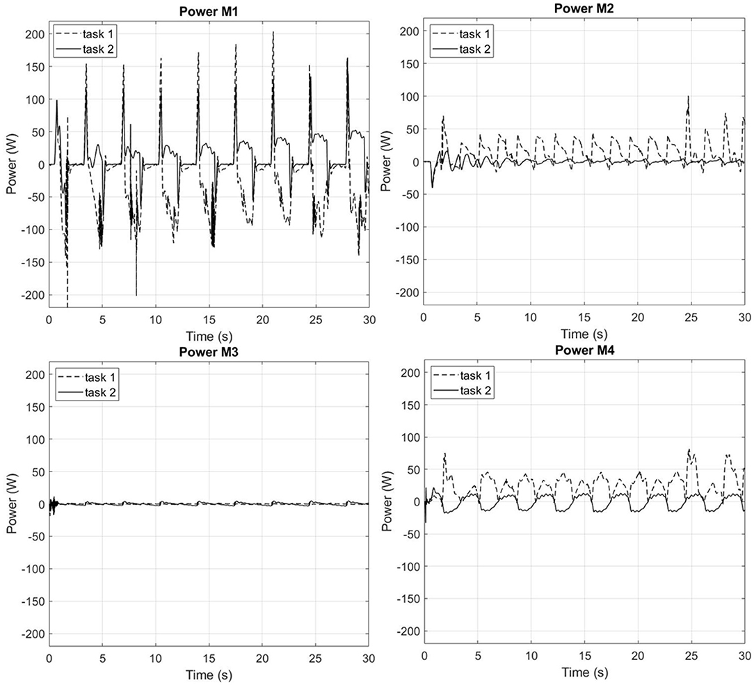
Figure 9. Speed 1 (0.73 m/s): Power (W) in the joints of the left leg of the biped-wheeled exoskeleton in task 1 and task 2 for the Motors M1, M2, M3, and M4.
Table 3 shows the maximum absolute peak values for speed 1 and for each motor. The differences between the values of the torque (ΔTorque) and power (ΔPower) obtained in the configuration of the task 2 compared to the task 1 are calculated using the following formulations:
From the graphs of Figures 8, 9, it can be seen that in task 2 (a case in which the subject has the joint stiffness > 0), the peaks of the torque and power of M1, M2, and M4 are lower than in task 1 (a case in which the subject has the joint stiffness = 0). In particular, it can be noted how the torque in task 2 is reduced compared to that of task 1 of 39.6, 38, and 49.14% in M1, M2, and M4, respectively; the power for the same motors is reduced from 34.61, 61.3, and 59.6%, respectively.
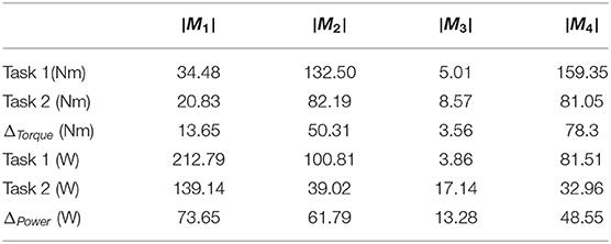
Table 3. Speed 1 (0.73 m/s): Maximum absolute peak values of the torque (Nm) and power (W) and their difference (ΔTorque, ΔPower) in Figures 8, 9.
On the contrary, the graph of M3 underlines an opposite behavior compared to the other graphs. For this motor (M3), more torque and power are requested in task 2 compared to the task 1. However, it is important to underline that the difference ΔTorque (ΔPower) calculated with 3) [and 4)] is only of 3.56 Nm (13.28 W). These results underline that the machine is more efficient if the subject is on board on it. This underlines also how the symbiotic physical interaction between humans and machines is the way to increase the sustainability.
The notes underlined for speed 1 are also underlined for speed 2, where the peaks of the torque and power are higher. The higher speed 2 allows us to point out, with more emphasis, the asymmetry in motion during the walking cycle underlined in a first time in Figure 6. The video attached to this paper allows us to underline these points.
7. Conclusion
This paper has analyzed the compliant physical interaction between the two multibody models of a novel biped-wheeled wearable machine and the subject on board. A very important result of this study is underlined by the inclusion of compliance in the joints of the model of the subject, which helps us to increase the efficiency of the biped-wheeled wearable machine during the walking cycle. In this paper, the walking cycles of the machine with the subject on board, with and without compliance of the joints, have been compared. The reduced torque and power, requested in the motors of the machine (if a subject with compliance in the joints is considered), have allowed us to design a novel generation of sustainable wheeled machines that will be more in symbiosis with human walking. Two different speeds are used for the simulation, underlining the good stability of the biped-wheeled machine, which is increased by the compliance in the joints of the subject. Future works should be oriented toward the design and development of the biped-wheeled machine for real implementations. The authors included the word “sustainable” because the core of this work is to reduce the torque and power consumptions of the novel machine, modifying the compliance of the subject. The reduction of the motor consumption and energy requested by the motors (varying the compliance of the subject on board) is a way to have a more “sustainable” machine. In this work, the authors would like to underline that the sustainability (as the way to construct novel machines more in symbiosis with the environment) may be obtained, increasing the symbiosis between the human and the machine. Thanks to the novelty underlined in this work, more (and different) machines may be designed, including human compliance to increase sustainability.
Data Availability Statement
All datasets generated for this study are included in the article/Supplementary Material.
Author Contributions
GT and GM performed the control architecture. GT did the simulation. AN and GM conceived the multibody models. AN implemented the first version of the Multibody Simulation. GM conceived, proposed, and started the research topic idea conceiving the Biped-Wheeled Exoskeleton system, managing and supervising the research work. All authors contributed to the article and approved the submitted version.
Conflict of Interest
The authors declare that the research was conducted in the absence of any commercial or financial relationships that could be construed as a potential conflict of interest.
Supplementary Material
The Supplementary Material for this article can be found online at: https://www.frontiersin.org/articles/10.3389/fmech.2020.581626/full#supplementary-material
References
Arora, A., and McIntyre, J. R. (2020). “Quasi-passive lower and upper extremity robotic exoskeleton for strengthening human locomotion,” in Sustainable Innovation. International Marketing and Management Research, eds Saxena Arora A., Bacouel-Jentjens S., Sepehri M., and Arora A (Cham: Palgrave Pivot). doi: 10.1007/978-3-030-30421-8_1
Awad, L. N., Esquenazi, A., Francisco, G. E., Nolan, K. J., and Jayaraman, A. (2020). The rewalk restore TM soft robotic exosuit: a multi-site clinical trial of the safety, reliability, and feasibility of exosuit-augmented post-stroke gait rehabilitation. J. Neuroeng. Rehabil. 17, 1–11. doi: 10.1186/s12984-020-00702-5
Borisoff, J., and Rafer, V. (2017). Mobility system including an exoskeleton assembly releasably supported on a wheeled base. US Patent 9849048, British Columbia Institute of Technology.
BostonDynamics (2017). Introducing Handle. Available online at: https://www.youtube.com/watch?v=-7xvqQeoA8c
BostonDynamics (2019). Handle Robot Reimagined for Logistics. Available online at: https://www.youtube.com/watch?v=5iV_hB08Uns
de Carvalho, G. J. A. (2018). Exoskeleton with cambered wheels for human locomotion. United States patent application US 15/576,714.
Hitachi (2010). HITACHI, EMIEW2 Adaptive suspension. Available online at: https://www.youtube.com/watch?v=CCl7GRa7W3o
IJHR (2020). Notable articles on Biped Robots. Available online at: https://www.worldscientific.com/worldscinet/ijhr
Lee, J., Kim, D., Ryoo, H.-Y., and Shin, B.-S. (2016). Sustainable wearables: wearable technology for enhancing the quality of human life. Sustainability 8:466. doi: 10.3390/su8050466
Loschi, A. (2020). Test and development of reduced scale exoskeleton robot (Master's thesis). Politecnico di Torino, Torino, Italy.
Ma, Q., Ji, L., and Wang, R. (2017). “Wheelwalker: a foot-wheel driving exoskeleton for the alternate walk of paraplegic patients,” in MATEC Web of Conferences (EDP Sciences), Vol. 108, 13003. doi: 10.1051/matecconf/201710813003
Ma, Q., Ji, L., Wang, R., and Wong, L.-N. (2018). Development of a foot-wheel driving exoskeleton for moving assistance of paraplegic patients. Proc. Instit. Mech. Eng. 232, 3171–3180. doi: 10.1177/0954406217735554
Maiorino, A., and Muscolo, G. G. (2020). Biped robots with compliant joints for walking and running performance growing. Front. Mech. Eng. 6:11. doi: 10.3389/fmech.2020.00011
Marcheschi, S., Salsedo, F., Fontana, M., and Bergamasco, M. (2011). “Body extender: whole body exoskeleton for human power augmentation,” in 2011 IEEE International Conference on Robotics and Automation (IEEE), 611–616. doi: 10.1109/ICRA.2011.5980132
Muscolo, G. G., Caldwell, D., and Cannella, F. (2017). Calculation of the center of mass position of each link of multibody biped robots. Appl. Sci. 7:724.
Muscolo, G. G., and Recchiuto, C. T. (2017). Flexible structure and wheeled feet to simplify biped locomotion of humanoid robots. Int. J. Human. Robot. 14:1650030. doi: 10.1142/S0219843616500304
Nicoli, A. (2020). Multibody model of a novel wheeled exoskeleton machine (Master's thesis). Politecnico di Torino, Torino, Italy.
Onishi, T., Arai, T., Inoue, K., and Mae, Y. (2003). Development of the basic structure for an exoskeleton cyborg system. Artif. Life Robot. 7, 95–101. doi: 10.1007/BF02481155
Panero, E., Muscolo, G. G., Gastaldi, L., and Pastorelli, S. (2020a). “Multibody analysis of a 3D human model with trunk exoskeleton for industrial applications,” in Multibody Dynamics 2019. ECCOMAS 2019. Computational Methods in Applied Sciences, Vol 53, eds A. Kecskeméthy and F. Geu Flores (Cham: Springer). doi: 10.1007/978-3-030-23132-3_6
Panero, E., Muscolo, G. G., Pastorelli, S., and Gastaldi, L. (2019). “Influence of hinge positioning on human joint torque in industrial trunk exoskeleton,” in Advances in Mechanism and Machine Science. IFToMM WC 2019. Mechanisms and Machine Science, Vol 73, ed T. Uhl (Cham: Springer). doi: 10.1007/978-3-030-20131-9_14
Panero, E., Muscolo, G. G., Pastorelli, S., and Gastaldi, L. (2020b). “Model based analysis of trunk exoskeleton for human efforts reduction,” in Advances in Service and Industrial Robotics. RAAD 2019. Advances in Intelligent Systems and Computing, Vol 980, eds K. Berns and D. Görges (Cham: Springer). doi: 10.1007/978-3-030-19648-6_47
Read, E., Woolsey, C., McGibbon, C. A., and O'Connell, C. (2020). Physiotherapists' experiences using the Ekso bionic exoskeleton with patients in a neurological rehabilitation hospital: a qualitative study. Rehabil. Res. Pract. 2020:2939573. doi: 10.1155/2020/2939573
Sartori, M., Maculan, M., Pizzolato, C., Reggiani, M., and Farina, D. (2015). Modeling and simulating the neuromuscular mechanisms regulating ankle and knee joint stiffness during human locomotion. J. Neurophysiol. 114, 2509–2527. doi: 10.1152/jn.00989.2014
Shamaei, K., Sawicki, G. S., and Dollar, A. M. (2013). Estimation of quasi-stiffness of the human hip in the stance phase of walking. PLoS ONE 8:e81841. doi: 10.1371/journal.pone.0081841
Song, Z., Tian, C., and Dai, J. S. (2019). Mechanism design and analysis of a proposed wheelchair-exoskeleton hybrid robot for assisting human movement. Mech. Sci. 10, 11–24. doi: 10.5194/ms-10-11-2019
Spadaro, F. T., and Muscolo, G. G. (2020). Influence of compliant joints in four-legged robots. Front. Mech. Eng. 6:16. doi: 10.3389/fmech.2020.00016
Tu, K. Y., and Lee, W. C. (2010). “Analysis and study of human joint torque and motion energy during walking on various grounds,” in Trends in Intelligent Robotics. FIRA 2010. Communications in Computer and Information Science, Vol. 103, eds Vadakkepat P., Kim, J.-H., Jesse, N., Al Mamun, A., Kiong, T. K., Baltes, J., Anderson, J., Verner, I., and Ahlgren, D (Berlin; Heidelberg: Springer). doi: 10.1007/978-3-642-15810-0_10
Zoccali, A., and Muscolo, G. G. (2021). “Comfort perception analysis of human models interfacing with novel biped-wheeled-exoskeletons,” in New Trends in Medical and Service Robotics. MESROB 2020. Mechanisms and Machine Science, Vol. 93, eds G. Rauter, P. C. Cattin, A. Zam, R. Riener, G. Carbone, and D. Pisla (Cham: Springer). doi: 10.1007/978-3-030-58104-6_3
Keywords: wheeled exoskeleton, wheeled wearable machine, exoskeleton, wearable robots, biped robot, legged robot, wheeled robot, personal vehicle
Citation: Trono G, Nicolì A and Muscolo GG (2020) Sustainable Compliant Physical Interaction in a Biped-Wheeled Wearable Machine. Front. Mech. Eng. 6:581626. doi: 10.3389/fmech.2020.581626
Received: 09 July 2020; Accepted: 11 September 2020;
Published: 26 November 2020.
Edited by:
Nicola Ivan Giannoccaro, University of Salento, ItalyReviewed by:
Leonardo Cappello, Sant'Anna School of Advanced Studies, ItalyChen Lv, Nanyang Technological University, Singapore
Somnath Chattopadhyaya, Indian Institute of Technology Dhanbad, India
Copyright © 2020 Trono, Nicolì and Muscolo. This is an open-access article distributed under the terms of the Creative Commons Attribution License (CC BY). The use, distribution or reproduction in other forums is permitted, provided the original author(s) and the copyright owner(s) are credited and that the original publication in this journal is cited, in accordance with accepted academic practice. No use, distribution or reproduction is permitted which does not comply with these terms.
*Correspondence: Giovanni Gerardo Muscolo, giovanni.muscolo@polito.it