Texturing of Glass Surface using Micro-slurry Jet Machining Process
 Hajime Yamaguchi
 Koshi Sakata2
  Yuta Nakashima
 Yoshitaka Nakanishi
- 1Graduate School of Advanced Science and Technology, Kumamoto University, Kumamoto, Japan
- 2Faculty of Engineering, Kumamoto University, Kumamoto, Japan
- 3Faculty of Advanced Science and Technology, Kumamoto University, Kumamoto, Japan
Existing methods for the microfabrication of convex structures on a glass surface require a complex and expensive masking process. In this study, a simple microfabrication method that combines the masking process using polyimide tapes and a micro-slurry jet (MSJ) process was developed. The masking process was performed using a CO₂ laser machine, and the surface of the processed glass was observed using a three-dimensional laser microscope. Although the geometric shape of the mask was not a perfect circle, convex structures with a diameter of approximately 1.0 mm and heights of more than 1.5 μm were formed on soda-lime glass surfaces. The deepest structures were observed to create convex structures with a height of 19 µm. The effects of the travel speed of the nozzle and number of repetitions of the MSJ process on the height of the convex structures on the glass surface were also investigated. It was found that the masking process combining polyimide tapes and the MSJ process could form high-convexity structures on the glass surface. The proposed method is expected to enable the fabrication of devices with various functional properties for materials that cannot be processed using existing methods.
1 Introduction
Surface design is a key factor in the functional performance of materials and devices. Typical examples are the high adherence of the surface of geckos' hands (Christensen-Dalsgaard et al., 2011), the inhibition of light reflection from the eyes of moths (Ko et al., 2011), and the Lotus effect due to the superhydrophobicity and self-cleaning property of the lotus leaves’ surface (Zorba et al., 2008). The design of a glass surface contributes not only to the tribological performance of the glass, but also to its optical performance. In recent years, the friction between the human skin and a glass surface has attracted attention owing to its use in anti-fouling films for smartphones. Furthermore, the friction between the skin and material surfaces has been reported to affect human emotions (van Kuilenburg et al., 2015; Bertheaux et al., 2020; Van Der Heide et al., 2013). Coatings for antifouling films were first developed to achieve antifouling properties (Kasmez et al., 2017). Wet etching (Panek et al., 2005) and dry etching (Kumaravelu et al., 2004) are typically used to impart microsurface structures to material surfaces. However, these methods require many procedures, reagents, and equipment (Yibas et al., 2013). Laser micromachining (Etsion, 2004; Sugioka, 2017) is a simpler method widely used for the surface treatment of glass. However, this method has been reported to have thermal effects to glass (Buerhop et al., 1990), which may affect its properties. It has been reported that the transparency of laser-treated and untreated surfaces deteriorates, causing changes in the light transmittance and other properties (Fu et al., 2013; Yilbas et al., 2014). Shibata et al. (2019) used a combination of photoresists and micro-slurry jets (MSJ) to micromachine brittle glass surfaces with antifouling properties and suitable skin surface friction. However, this masking process was time-consuming and required specialized equipment.
In this study, a simple method for the microfabrication of convex structures on a glass surface was developed by combining the masking process using polyimide tapes and an MSJ process. The respective techniques of using polymer masks and powder blasting to form a textured surface on glass already exist (Slikkerveer, 1999; Bruzzone et al., 2008; Costa and Hutchings, 2015; Gachot et al., 2017). The most important feature and difference is that we used MSJ, which is a processing method that differs from general powder blasting in that it employs small hard abrasive grains and a large amount of water as a solvent to process even brittle materials smoothly without chipping (Baba et al., 2019), and polyimide film, which has wear resistance capability to MSJ. The proposed method was employed to process a glass surface, which was then examined using a three-dimensional (3D) laser microscope.
2 Materials and Methods
2.1 Proposed Microfabrication Process
Figure 1 shows a schematic of the proposed microfabrication method. Flat soda-lime glass slides (SS1225, MATSUNAMI) with an area of 76 × 26 mm2 and a thickness of 1.3 mm were processed in this study. The preparation method consisted of a masking process and an MSJ process, which is a mechanical removal process (Nakanishi et al., 2021). After cleaning the glass surface with ethanol, a 55 µm-thick polyimide tape with silicone adhesive was applied, taking care not to allow air bubbles to enter between the tape and the glass. Then, masking was performed using a CO₂ laser machine (LaserPro, MERCURY II, Comnet). After the masking process, the MSJ process was performed. Finally, the sacrificial patterns were removed by ultrasonic cleaning for 10 min using acetone as a solvent. Figure 2 shows the design of the mask fabricated in this study. Masks with a diameter of 1.0 mm and a pitch of 2.0 mm were fabricated using MSJ, which consists of blowing a slurry mixed with polygonal alumina with compressed air to process the surface of the material. Figure 3 shows a schematic of the MSJ process and path of the nozzle movement. The process parameters of the MSJ were designed by conducting unmasked processing tests prior to the experiment to create convex structures with heights greater than 1.0 µm in soda lime glass. The injection pressure of the MSJ was 0.3 MPa, and the fine particles were polygonal fine alumina particles with an average size of 1.2 µm (#8000), which are low-cost and sufficiently hard. Because the MSJ has a 1 mm wide square jet nozzle, the machining depth will become shallow due to interference with the previously machined area if we attempt to machine at a pitch smaller than 1 mm. Therefore, the machining pitch was set to 2.0 mm to avoid interference. The injection nozzle can be moved parallel to the processing surface using a numerical control system. In this study, three MSJ nozzle movement speeds of 0.5, 1.0, and 1.5 mm/s were applied to observe the effect of the MSJ nozzle movement speed on the height of the convex structure formed on the glass surface. The effect of the slurry on the adhesive of the tape when repeating the MSJ process was investigated. The MSJ process was repeated eight times with an MSJ nozzle movement speed of 0.5 mm/s.
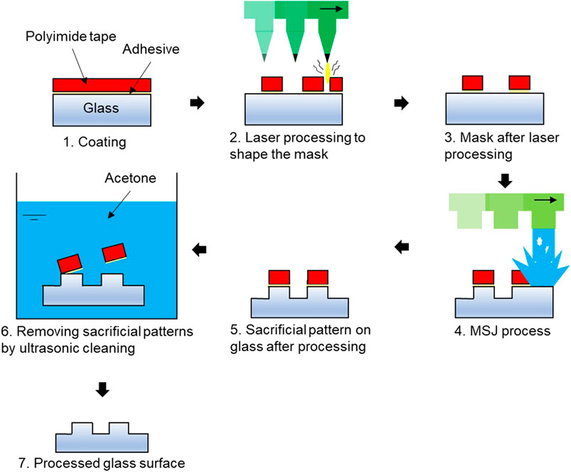
FIGURE 1. Method for the formation convex structures on glass surfaces.
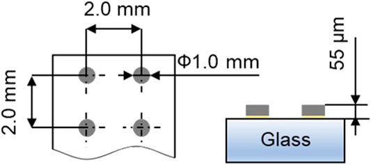
FIGURE 2. Diagram of the mask produced in this study.
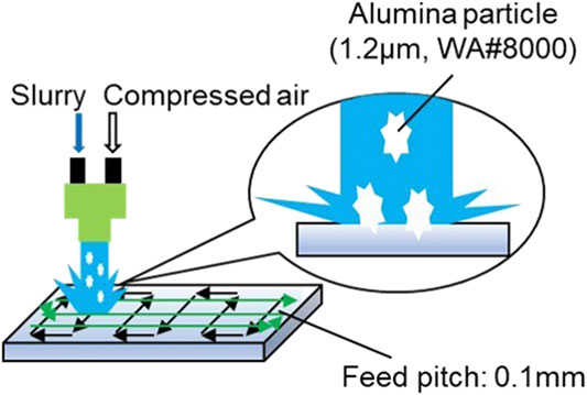
FIGURE 3. MSJ processing and movements of the injection nozzles.
2.2 Evaluation of Glass Surfaces With Convex Structures
3D images, color images, and the profiles of the processed glass surfaces were observed using a laser microscope (LEXT 3D MEASURING LASER MICROSCOPE, OLS5000, OLYMPUS).
3 Results and Discussion
3.1 Effect of MSJ Nozzle Movement Speed
Figure 4 shows 3D maps, color images, and profiles of the mask formed on the glass surface. The measured height of the convexity coincided with the thickness of the tape, indicating the successful application of the mask. Figure 4 shows the 3D maps, color images, and profiles of the glass surface after the masking process. From the figure, it can be observed that the surface does not present perfect circles with a diameter of 1 mm, as expected, but some unnecessary fibrous polyimide tape, which could not be completely removed by laser processing, remained as black deposits around the mask, as can be seen in the color image in Figure 4. We selected the output power and speed of the CO₂ laser machine so that the laser beam will not affect the glass surface; the values of the laser power and speed are 12.5 W and 427 mm/s, respectively. Figure 5 shows the 3D maps, color images, and profiles of the mask formed on the glass surface after optimization. It can be observed that the masking film was still in place, hence, the mask strength was considered to be sufficient. The process parameters of the MSJ were designed by conducting unmasked processing tests prior to the experiment to create convex structures with heights greater than 1.0 µm in soda lime glass. Therefore, it can be observed that the height of the convex structure is higher than 1.0 µm in Figure 5 compared with Figure 4. The fibrous state of the mask observed in Figure 4 became smaller, and the mask attained a better circular shape. This is attributed to the fact that the fibrous portions were either weakly attached to the glass surface or completely free, so that they could be easily removed using the MSJ process. Figure 6 shows the glass surface after the removal of the sacrificial pattern. It can be observed that the acetone dissolved the adhesive layer of the polyimide tape. When the movement speed of the MSJ nozzle was 1.5, 1.0, and 0.5 mm/s, the convex structures reached heights of 1.6, 2.4, and 6.2 μm, respectively. This is because a slower movement of the nozzle leads to a longer processing time of the same spot per unit time and hence, a greater machining depth. However, because the movement speed of the nozzle and the machining depth were not linearly approximated, it was difficult to adjust the machining depth. In addition, the profile shows that there are no chips and a smooth surface has been created.
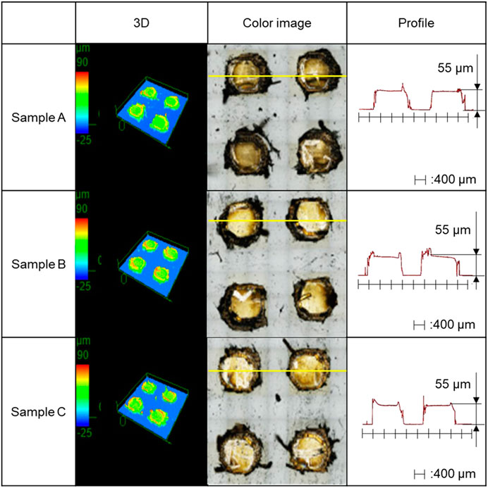
FIGURE 4. 3D map, color image, and profile of the mask formed on the glass surface.

FIGURE 5. 3D map, color image, and profile of the mask on the glass surface of the MSJ process.
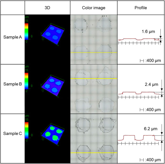
FIGURE 6. 3D map, color image, and profile of the glass surface after the removal of the sacrifical pattern.
3.2 Assessing the Impact of the Iterative MSJ Process
The effects of repeated MSJ treatments on the convexity of the structures formed on the glass surface were investigated. Figure 7 shows the 3D map, color image, and profiles of the glass surface when the mask tape peeling off during repeated MSJ treatment. It can be observed that the mask peeled off during repetitive processing and that convex structures with various heights were formed. This is attributed to the variation in the time of mask peeling, which in turn is attributed to a decrease in the adhesive strength of the adhesive tape. The decrease in adhesion was thought to be due to the increase in the exposure time to the slurry with the increase in the processing time and the repeated processing at the same location. In turn, the adhesion of the tapes is thought to be reduced by the irradiation of the masks with the laser beam during the fabrication of the masks. As a solution to this problem, changing the angle of slurry projection was considered. However, since MSJ uses particles, the angle at which they hit the material surface must be perpendicular to achieve sufficient removal. Furthermore, no attempt was made to change the projection angle because it was considered that if the particles are not projected perpendicularly, the slurry would penetrate more easily into the gap between the mask made of polyimide tape and the glass surface, increasing the effect of shortening the life of the mask. Therefore, instead of removing all the tape parts, except the mask, only the periphery of the mask was cut to reduce the degradation of the adhesive during mask fabrication by shortening the time of exposure of the tape to laser light. Figure 8 shows the results of the glass surface after repeating the MSJ process. The laser power of the CO₂ laser machine was 12.5 W and the speed was 427 mm/s. It can be observed from the figure that a uniform convex structure with a height of 19 μm was formed on the glass surface. In addition, the profile shows that there are no chips and a smooth surface has been created. This indicates that the proposed masking process is effective when the MSJ process is repeated. This was verified by repeating the masking process eight times when a convex structure with a height of 6.2 µm was created at a nozzle moving speed of 0.5 mm/s. In other words, the relationship between the number and depth of MSJ processing steps is not linear. However, it was observed that all the masks on the glass surface were already removed after processing. Therefore, the MSJ process was carried out for some time even after all the masks were removed during processing. This may have resulted in a lower height of the convex structure.
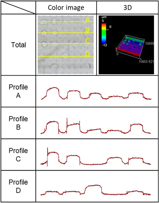
FIGURE 7. 3D map, color image, and profile of the glass surface when the mask tape peeling off during repeated MSJ treatment.
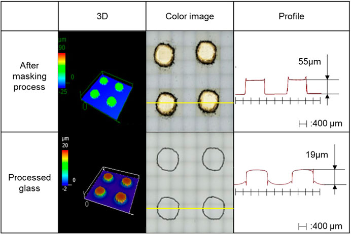
FIGURE 8. 3D map, color image, and profile of the mask created on the glass surface and glass surface after repeating the MSJ process.
4 Conclusion
We developed a method for the formation of glass surfaces with micro convex structures. The method combines the masking process and the MSJ process using polyimide tapes as the mask material. Using the method, convex structures with diameters of 1 mm, pitches of 2 mm, and heights of 1.6–19 µm were formed, and it was found that the MSJ process was effective in creating deeper convex structures. It was confirmed that the shape of the mask was transferred to the glass surface after the MSJ process. In the future, the accuracy of the masking process should be improved to create more shapes and micro-level convex structures on glass surfaces.
Data Availability Statement
The original contributions presented in the study are included in the article/Supplementary Material, further inquiries can be directed to the corresponding author.
Author Contributions
HA designed this research work and wrote the manuscript. KS and KK conducted the experiments. Both YNs managed and supervised all aspects of this work.
Funding
This work was supported by the JSPS KAKENHI Grant Number 19KK0096, the Environment Research and Technology Development Fund (1–1908) of the Environmental Restoration and Conservation Agency of Japan, and the Interdisciplinary Research Project of the Institute of Industrial Nanomaterials (IINa), Kumamoto University.
Conflict of Interest
The authors declare that the research was conducted in the absence of any commercial or financial relationships that could be construed as a potential conflict of interest.
References
Baba, T., Nakashima, Y., Takahashi, S., Matsubara, T., Yin, L., and Nakanishi, Y. (2019). Micro‐slurry jet for surface processing of dental ceramics. Biosurf. Biotribol. 5, 8. doi:10.1049/bsbt.2018.0028
Bertheaux, C., Toscano, R., Fortunier, R., Roux, J.-C., Charier, D., and Borg, C. (2020). Emotion Measurements through the touch of materials surfaces. Front. Hum. Neurosci. 13, 455. doi:10.3389/fnhum.2019.00455
Bruzzone, A. A. G., Costa, H. L., Lonardo, P. M., and Lucca, D. A. (2008). Advances in engineered surfaces for functional performance. CIRP Annals. 57, 750. doi:10.1016/j.cirp.2008.09.003
Buerhop, C., Blumentha, B., Weissmann, N., and Biermann, SL. (1990). Glass surface treatment with excimer and CO₂ lasers. Appl. Surf. Sci. 46, 430–434. doi:10.1016/0169-4332(90)90184-2
Christensen-Dalsgaard, J., Tang, Y., and Carr, C. E. (2011). Binaural processing by the gecko auditory periphery. J. Neurophysiol. 105, 1992–2004. doi:10.1152/jn.00004.2011
Costa, H., and Hutchings, I. (2015). Some innovative surface texturing techniques for tribological purposes. Proc. IME J. J. Eng. Tribol. 229, 429. doi:10.1177/1350650114539936
Etsion, I. (2004). Improving tribological performance of mechanical components by laser surface texturing. Tribol. Lett. 17, 733. doi:10.1007/s11249-004-8081-1
Fu, L.-M., Ju, W.-J., Yang, R.-J., and Wang, Y.-N. (2013). Rapid prototyping of glass-based microfluidic chips utilizing two-pass defocused CO2 laser beam method. Microfluid. Nanofluidics. 14, 479. doi:10.1007/s10404-012-1066-8
Gachot, C., Rosenkranz, A., Hsu, S. M., and Costa, H. L. (2017). A critical assessment of surface texturing for friction and wear improvement. Wear 372–373, 21. doi:10.1016/j.wear.2016.11.020
Kesmez, Ö., Tamsü Selli, N., Tunalı, A., Akarsu, E., Akarsu, M., and Arpaç, E. (2017). Fingerprint resistant coatings for stainless steel substrates. Prog. Org. Coat. 112, 51. doi:10.1016/j.porgcoat.2017.07.003
Ko, D.-H., Tumbleston, J. R., Henderson, K. J., Euliss, L. E., DeSimone, J. M., Lopez, R., et al. (2011). Biomimetic microlens array with antireflective "moth-eye" surface. Soft Mat. 7, 6404. doi:10.1039/C1SM05302G
Kumaravelu, G., Alkaisi, M. M., Bittar, A., Macdonald, D., and Zhao, J. (2004). Damage studies in dry etched textured silicon surfaces. Curr. Appl. Phys. 4, 108. doi:10.1016/j.cap.2003.10.008
Nakanishi, Y., Nakashima, Y., and van der Heide, E. (2021). Microstructuring glass surfaces using a combined masking and microslurry-jet machining process. Precis. Eng. 67, 172. doi:10.1016/j.precisioneng.2020.09.018
Panek, P., Lipiński, M., and Dutkiewicz, J. (2005). Texturization of multicrystalline silicon by wet chemical etching for silicon solar cells. J. Mater. Sci. 40, 1459. doi:10.1007/s10853-005-0583-1
Shibata, K., Nakashima, Y., and Nakanishi, Y. (2019). Anti-fingerprint glass surface created by mechanical removal process. Jbse 14, 19. doi:10.1299/jbse.19-00388
Slikkerveer, P. J. (1999). Model for patterned erosion. Wear 233–235, 1–756. doi:10.1016/S0043-1648(99)00177-5
Sugioka, K. (2017). Progress in ultrafast laser processing and future prospects. Nanophotonics 6, 393. doi:10.1515/nanoph-2016-0004
Van Der Heide, E., Zeng, X., and Masen, M. A. (2013). Skin tribology: Science friction? Friction 1, 130. doi:10.1007/s40544-013-0015-1
van Kuilenburg, J., Masen, M. A., and van der Heide, E. (2015). A review of fingerpad contact mechanics and friction and how this affects tactile perception. Proc. IME J. J. Eng. Tribol. 229, 243. doi:10.1177/1350650113504908
Yilbas, B. S., Khaled, M., Abu-Dheir, N., Al-Aqeeli, N., Said, S. A. M., Ahmed, A. O. M., et al. (2014). Wetting and other physical characteristics of polycarbonate surface textured using laser ablation. Appl. Surf. Sci. 320, 21. doi:10.1016/j.apsusc.2014.09.052
Yilbas, B. S., Khaled, M., Abu-Dheir, N., Aqeeli, N., and Furquan, S. Z. (2013). Laser texturing of alumina surface for improved hydrophobicity. Appl. Surf. Sci. 286, 161. doi:10.1016/j.apsusc.2013.09.040
Keywords: removal process, masking process, micro-slurry jet, high-performance, surface engineering
Citation: Yamaguchi H, Sakata K, Kasamura K, Nakashima Y and Nakanishi Y (2021) Texturing of Glass Surface using Micro-slurry Jet Machining Process. Front. Mech. Eng 7:631093. doi: 10.3389/fmech.2021.631093
Received: 19 November 2020; Accepted: 14 January 2021;
Published: 18 February 2021.
Edited by:
Giuseppe Carbone, Politecnico di Bari, ItalyReviewed by:
Antonio Ancona, Institute of Photonics and Nanotechnologies (IFN), ItalyHenara Lillian Costa, Federal University of Rio Grande, Brazil
Copyright © 2021 Yamaguchi, Sakata, Kasamura, Nakashima and Nakanishi. This is an open-access article distributed under the terms of the Creative Commons Attribution License (CC BY). The use, distribution or reproduction in other forums is permitted, provided the original author(s) and the copyright owner(s) are credited and that the original publication in this journal is cited, in accordance with accepted academic practice. No use, distribution or reproduction is permitted which does not comply with these terms.
*Correspondence: Yoshitaka Nakanishi, y-naka@mech.kumamoto-u.ac.jp