Prediction of Contact and Lubrication Characteristics of Micro-textured Surface Under Thermal Line Contact EHL
 Jiang Zhao1,2
  Zhengminqing Li
- 1College of Mechanical and Electrical Engineering, Nanjing University of Aeronautics and Astronautics, Nanjing, China
- 2National Key Laboratory of Science and Technology on Helicopter Transmission, Nanjing University of Aeronautics and Astronautics, Nanjing, China
In this study, a method combining numerical surface generation technology and three-dimensional hot-line contact EHL is employed to evaluate the contact characteristics of micro-textured surfaces under high-load line contact. Based on numerical simulation, the film thickness, film pressure, friction coefficient and surface flashing temperature of the virtual texture surface with different cross-sectional shapes and sizes are studied. On this basis, the subsurface stress at the contact point is calculated by the DC-FFT algorithm. The results show that, compared with a smooth surface, the micro-textures of different shapes all increase the average oil film thickness of the surface and reduce the friction coefficient, but at the same time lead to an increase in the contact stress of the surface. By changing the width and depth of the texture, the maximum film pressure has changed by 11.4 and 18.5%, respectively.
Introduction
It has been reported that micro-texture can improve surface properties by increasing and reducing friction (Yuan et al., 2011; Gachot et al., 2017; Codrignani et al., 2020), and has been successfully used in bearings, seals and other mechanical parts. (Wang, 2014; Gropper et al., 2016). Due to the diversity of the shape and arrangement of the micro-textures and the micro-textures exhibiting different tribological effects under conditions such as dry contact, boundary lubrication and full-film lubrication, an in-depth understanding of lubrication and friction properties is essential for selecting the textured surface required for specific conditions (Gachot et al., 2013; Taee et al., 2017; Wu et al., 2017; Ito et al., 2020). Experimental research is applied to obtain the friction or film thickness data of different micro-textured surfaces, and the comparison based on the data is helpful for the selection of micro-texture (Gadeschi et al., 2012; Rosenkranz et al., 2016). However, the experimental evaluation of a complete micro-textured surface is expensive and time-consuming. Numerical simulation has become another resource-saving method for exploring the lubrication and friction characteristics of micro-textured surfaces, and it is more accurate and faster.
The artificially generated micro-texture pairs will change the surface morphology and significantly affect the performance of the lubricating film, which in turn affects the load and wear of the surface. Yu and Sadeghi (Yu and Sadeghi, 2001) discussed the effect of groove geometry, groove depth, groove width, groove shape and groove amount on the load support of thrust washers. Kovalchenko et al. (Kovalchenko et al., 2004) conducted a series of experimental studies on micro-textured surfaces with different depths, densities and diameters to understand their friction behavior. Woloszynski et al. (Woloszynski et al., 2014). investigate the effects of elliptical grooves and trapezoidal dents on the maximum pressure, load capacity, friction coefficient and minimum film thickness of a limited fluid dynamic bearing. Khaemba et al. (Khaemba et al., 2020) used the tribological tests to investigate the effect of three different microtextures on the tribological properties of the friction modifier molybdenum dialkyldithiocarbamate. The effects of important geometric parameters such as the shape, distribution, density, and depth of the micro-texture on the lubrication characteristics have been also analyzed (Pettersson and Jacobson, 2004; Vlădescu et al., 2016). However, the micro-textured surface deformation caused by high contact pressure increases the complexity of the micro-texture lubrication characteristics research compared with the low contact pressure friction pair mentioned above.
Nanbu et al. (Nanbu et al., 2008) investigated the effect of the direction, directional angle, characteristic continuity and aspect ratio of micro-textures on lubrication characteristics on point contact. Ali et al. (Ali et al., 2015) analyzed the influence of laterally restricted microgrooves on film thickness and friction behavior in EHL point contact. Marian et al. (Marian et al., 2019) discussed the effects of structural parameters such as the depth and diameter of micro-textures and the relative position of micro-texture and counter-body on lubrication and friction on point contact. Jadhav et al. (Jadhav et al., 2019) investigated the effects of spherical, rectangular and triangular textures on the lubrication characteristics of line contact EHL based on a magnetohydrodynamic lubrication model. There are many studies on the lubrication characteristics of micro-textured surfaces. In addition, contact stress is another very important factor for the design of mechanical parts. When the two elements are in contact and move relative to each other, due to the entrainment of pressurized fluid during the mixing and lubrication process, interface normal and shear traction occur. The interaction of the surface has caused drastic changes in the underground stress, which profoundly affects the surface contact characteristics such as rolling contact fatigue, crack growth and wear. Zhu et al. (Zhu et al., 2009). studied the subsurface stress of typical gear tooth surfaces such as shaved and ground. Yan et al. (Yan et al., 2013) discusses the stress and fatigue life of a three-dimensional sinusoidal surface with variable wavelengths in the x and y directions. Yang et al. (Yang et al., 2019). analyzed the maximum von Mises stress of smooth, ground and honing surfaces under the same rolling conditions. However, there are few reports on the contact stress of micro-textured surfaces.
Based on the fact that there are a lot of reports focusing on the lubricating properties such as the local film pressure and film thickness on the micro-textured surface, and fewer reports focus on the details of contact stress on the micro-textured surface. This research established a simulation prediction model for the analysis of micro-textured surface characteristics with contact and lubrication analysis capabilities based on the numerical surface generation technology and the three-dimensional thermal hybrid EHL method. The modeling system can be invoked as a predictive tool to predict the lubrication and contact status of different micro-textured surfaces. In addition, the effect of micro-textures with different cross-sectional shapes and sizes on surface lubrication properties and contact stress is also discussed based on the prediction model. The main purpose of this research is to provide technical cost and parameter basis for the improvement of micro-textured surface lubrication performance.
Theoretical Background
Three-Dimensional Line-Contact Thermal EHL Model
The analysis of lubrication characteristics is based on three-dimensional line-contact thermal mixed EHL complete numerical solution model. This model was first proposed by Ren et al. (Ren et al., 2009) to predict contact and lubrication state characteristics. In the hydrodynamic region, pressure is controlled by the Reynolds equation expressed as follows:
Lubricating film thickness includes macroscopic contact geometry, surface elastic deformation and microscopic surface roughness. The local lubricant film thickness is calculated as follows:
where R(t) is the effective radius of curvature over the contact width, δ1 and δ2 is the roughness amplitudes of surface1 and surface2, respectively, υ is the elastic deformation of the surfaces. The elastic deformation term is derived from Boussinesq’s integral formula (Wang et al., 2003), which is calculated as follows:
Generally, the discrete convolution and fast Fourier transform (DC-FFT) algorithm proposed by Liu et al. (Liu et al., 2000) can be used to analyze the elastic deformation of the rough surface in the inverse contact. For the line contact problem, Chen et al. (Chen et al., 2008) modified the DC-FFT algorithm with duplicated padding, which is called the DCD-FFT algorithm. It uses a hybrid padding strategy in the extended domain to improve the DC-FFT algorithm i.e., duplicated padding excitation in the periodic direction with infinitely long contact geometry and zero padding excitation in the direction of the finite contact width.
The density of lubricating oils is adopt the Dowson-Higgison dense-pressure relationship (Dowson, 1977).
The load applied in the EHL area is balanced by the pressure integral in the entire area. The load balance equation is shown as follows:
A finite length L in y direction is set as the solution domain, L/2 ≥ y ≥ -L/2, and the boundary condition for solving the Reynolds equation is written as (Shi et al., 2019):
When the oil film ruptures or cavitation, the following boundary conditions are used:
Temperature Rise of Two Contact Surfaces
A large amount of frictional heat will be generated at the contact interface of the two surfaces that are moving relative to each other, which causes an instantaneous temperature rise on the contact interface between the two surfaces, which is called flash temperature. If the surface temperature is too high, it is easy to stick and glue the contact interface and accelerate the failure of parts. Therefore, temperature distribution is a factor that must be considered in the design of mechanical parts. The analytical formula of temperature rise proposed by Zhu and Cheng (Zhu and Cheng, 1989) is the key to the solution of temperature rise in this paper.
where q is the heat generated by either interface friction and lubricant shearing,
Subsurface Stress of Contact Surface
For high-load contact, the size of the contact area is small compared to the radius of curvature of the contact body surface. The contact stress is concentrated near the contact area and decreases rapidly as the distance from the contact area increases. In other words, the contact stress does not depend on the shape of the contact body far away from the contact area, nor does it depend on the support method of the contact body. Therefore, one of the contact bodies can be regarded as a semi-infinite elastic body in the stress calculation. Under the action of the normal concentrated force P, the relationship between any point in the elastic semi-infinite body and the point of action is shown in Figure 1.
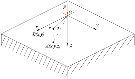
FIGURE 1. The effect of normal concentration on any point in the semi-infinite body.
Based on the stress and displacement generated from the normal concentrated force, Johnson (Johnson, 1985) gave an expression for calculating the deformation and stress caused by any distributed load using the superposition method.
where
According to the principle of force independence and superposition, when an elastic semi-infinite body is subjected to a distributed normal force p (ξ,η), the stress of any point A (x, y, z) in the semi-infinite body can be obtained according to the principle of superposition, as follows:
where,
According to the principle of force independence and superposition, when an elastic semi-infinite body is subjected to a distributed tangential force s (ξ,η), the stress at any point A(x, y, z) in the semi-infinite body can be superimposed in a similar way.
Three-dimensional subsurface stress caused by surface normal stress and tangential shear stress can be calculated by the following integration.
where *means convolution, p (ξ, η) is the normal force, and s (ξ, η) is the tangential force.
Taking the normal stress calculation process as an example, the continuous form of the relationship between the subsurface stress and the normal pressure is:
The discrete form of the equation, that is, the form defined by pressure and influence coefficient is as follows:
For the elastic half-space stress, the solution method proposed by Boussinesq and Cerruti is employed (Yan et al., 2014). The influence coefficients under normal stress and tangential stress are obtained by the results of Liu et al. (Liu and Wang, 2002). Similar to the solution of elastic deformation, the DC-FFT method can be used to calculate the underground stress field.
Numerical Simulation and Experimental Verification Process
In this study, the experimental and numerical simulation contact conditions are the same for all cases. The entire calculation process is shown in Figure 2. First, the friction coefficient of a smooth surface without lubrication is obtained by a friction testing machine, and the boundary friction coefficient estimated by the experiment is used as the input data of the model. Then, through the simulation calculation of the hydrodynamic friction of the micro-textured surface. It is worth noting that in the process of numerical simulation of micro-textured surfaces, the smooth surface solution under the same working conditions is usually calculated first, and then the numerical rough surface is brought in by setting the same smooth solution as the initial value. And after enough time steps, the micro-textured surface contact characteristics are obtained. Finally, the friction coefficient calculated by thermal EHL simulation is compared with the friction coefficient measured by experiment. Based on this comparison, the model can be modified to better agree with the experiment. The improved model can then be reused for more simulation situations using the same lubricant.
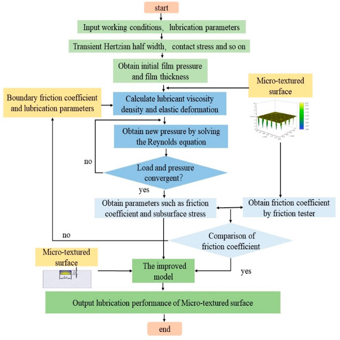
FIGURE 2. Numerical simulation and experimental verification process.
Experimental
In the experiment, the three-dimensional rough surface was measured by a 3D non-contact surface profilometer with the resolution of 0.2 μm and 10 times magnification lens. The measurement length and width of the surface are 1.757 and 1.406 mm, which cover the nodes of 640 × 512 in x and y directions, respectively. The friction tests were performed under ambient temperature (20–25°C). In the friction experiment, the test material is GH15 Superalloy. The coefficient of friction is measured by the commercial friction tester, as showed in Figure 3. The upper surface of the two contact surfaces is a polished surface, and the other surface is a test surface. And the force of the elastic cantilever can be measured in both horizontal and vertical planes, so that the normal load, the friction force and therefore the friction coefficient can be determined. 4106 aviation lubricating oil is used for friction test, its dynamic viscosity η0 = 0.0104 Pa s.
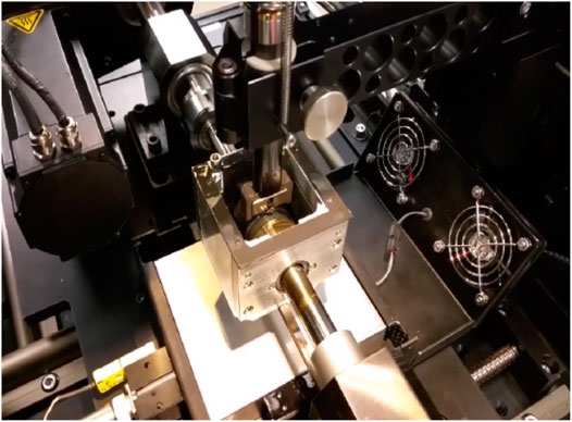
FIGURE 3. Commercial friction tester.
Laser surface texturing is used to process micro-textured arrays on the test surface. In order to avoid the interference of the test results from the original surface roughness, it is necessary to ensure that the surface roughness of the non-textured specimens is low before laser micro-texturing. The surface polishing process is used in the experiment to control the surface roughness Ra between 15–25 nm. After the surface is treated with laser texturing, the partially melted metal cools and accumulates in the area around the micro-pits, so that the edges of the micro-pits form protrusions like craters. After finishing the laser textured surface processing, the micro-textured surface is polished and cleaned again for eliminating the adverse effects of protrusions around the micro-texture. The micro-textured surface after a series of processing is illustrated in Figure 4.
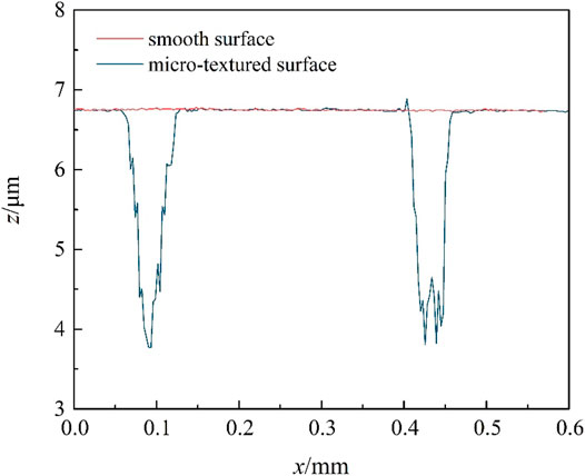
FIGURE 4. The smooth and micro-textured surface.
Results and Discussion
Numerical Simulation and Experimental Verification
The method proposed by Wang et al. was used to determine the correlation coefficient of the rheological model (Wang et al., 2007). The coefficient of friction of the micro-textured surface obtained from the three-dimensional EHL model at different velocities is compared with the friction coefficient obtained in the experiment, and a more accurate model is obtained through continuous iteration. In this case, the applied load per unit length is 325.1654 N/mm and the Hertz contact stress is fixed at pH = 728 MPa, and the velocities is 0.01 m/s, 0.1 m/s, 1 m/s, 1.5 m/s, 2 m/s, 2.5 m/s, and 3 m/s, respectively. In the simulation, in order to reduce the effect of starvation on the film thickness, the entrance distance is set to 3.5 a from the contact center line x = 0 and the exit distance is 1.5 a (Zhu et al., 2014). Progressive mesh density PMD method to ensure the convergence and accuracy of the film thickness results (Zhu, 2007). Figure 5 shows the relationship between the coefficient of friction and the velocity. In numerical simulation and experiment. The coefficient of friction is obtained by numerical simulation and experimental measurement of the micro-textured surface. Three measured data during stable operation are selected, and the average value of these data is calculated to obtain the experimental coefficient of friction at each velocity.
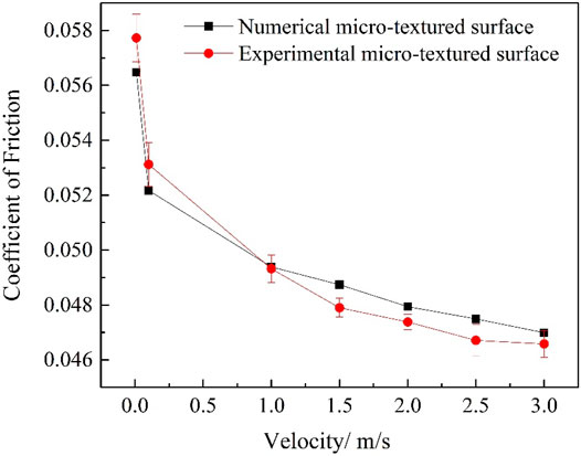
FIGURE 5. The relationship between the friction coefficient and the velocity.
It can be seen from Figure 5 that with the continuous increase of the velocity, the lubrication state between the contact interfaces changes continuously and smoothly from dry contact to mixed lubrication and full film lubrication. In addition, Due to the difference of the laser processing surface, there is a slight difference between the friction coefficient and the friction coefficient of the sample in the numerical simulation, but the relationship between the friction coefficient of the micro-textured surface and the velocity obtained by numerical calculation is similar to that of the experimental friction coefficient. The two curves show the same trend as the velocity increases, and the maximum difference between calculation and measurement at seven sets of speeds from 0.01 to 3 m/s is 4.52%, which indicates that the 3D thermal mixed EHL model can be used to provide a good prediction of the friction coefficient of mixed lubrication, and further predict other relevant lubricating properties of the micro-textured surface.
Effect of the Cross-Sectional Shape of Micro-texture on Lubrication Characteristics
It is difficult to precisely control the texture shape using laser texturing technology. Therefore, the combination of numerical surface generation technology and 3D thermal EHL model is used in this study to accurately analyze the effect of microstructure parameters on the contact characteristics of micro-textured surface. Firstly, the effect of the cross-sectional shape of micro-texture on the lubrication characteristics is discussed in this section based on the contact parameters. numerical surface generation technology is applied to generate micro-textures with different cross-sectional shapes on smooth surfaces, including R, T, RT1, RT2, IT and H. as illustrated in Table 1. The surface texture is located in the middle of the Hertz contact ellipse, as shown in Figure 6. The surface1 is smooth, while the surface2 is numerically textured. In simulations, the maximum Hertzian stress pH = 728 MPa and the Hertz contact radius a = 0.1658 mm. The entrainment velocity U = 3 m/s. In particular, in order to reduce the resulting error caused by the difference in micro-texture volume caused by different cross-sectional shapes, the length of the pit in the y direction is adjusted according to the surface area of the different cross-sectional shapes. At the same time, the depth and width of the micro texture of each shape are the same.
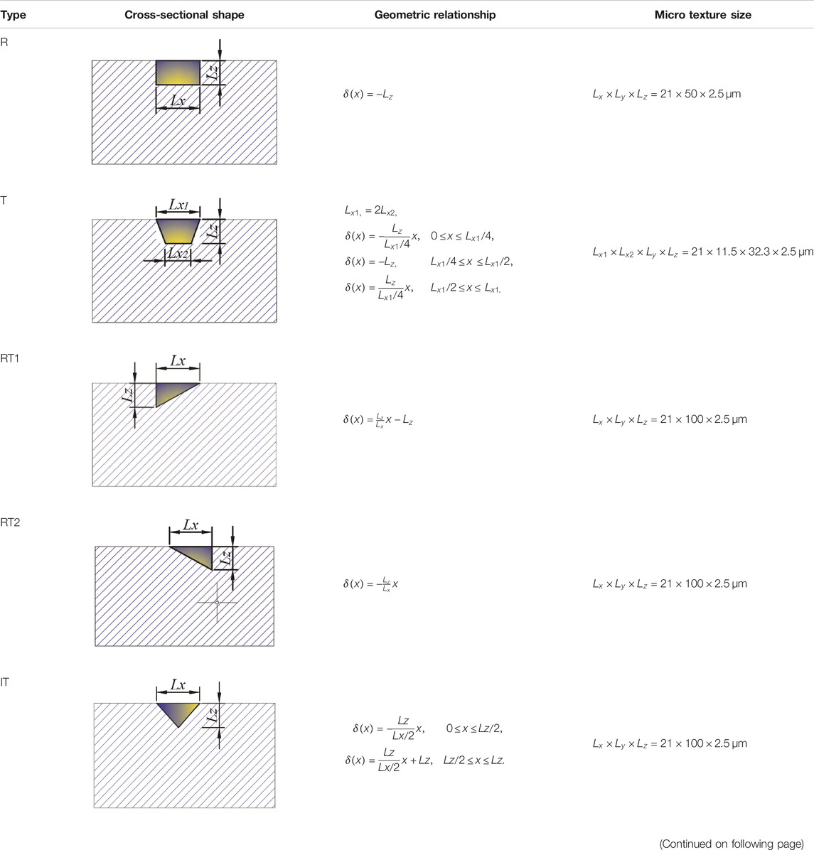
TABLE 1. The cross-sectional shape of micro-texture.
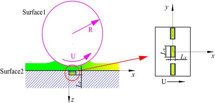
FIGURE 6. The Position of micro-texture on surface.
Taking H micro-texture as an example, the three-dimensional film pressure, temperature rise and von Mises stress distribution of the smooth surface and the micro-textured surface are shown in Figure 7.
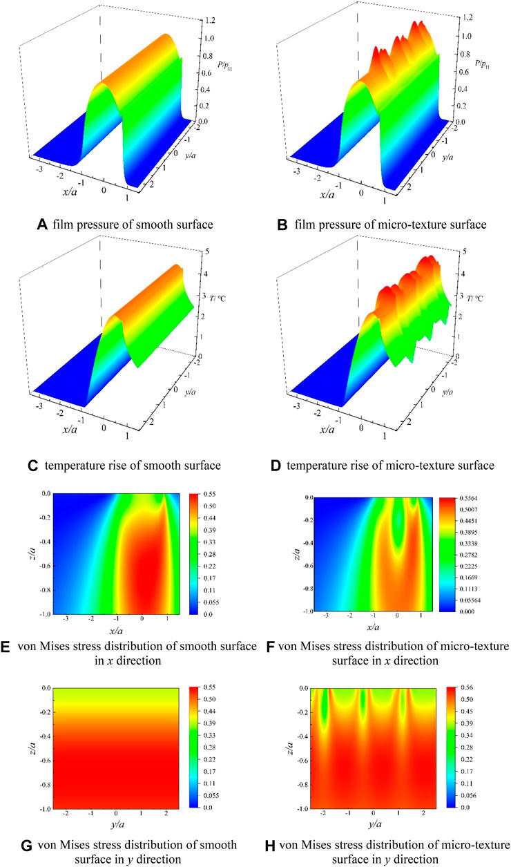
FIGURE 7. Lubricating characteristics of smooth surface and micro-textured surface. (A) Film pressure of smooth surface. (B) Film pressure of micro-texture surface. (C) Temperature rise of smooth surface. (D) Temperature rise of micro-texture surface. (E) von mises stress distribution of smooth surface in x direction. (F) von mises stress distribution of micro-texture surface in x direction. (G) von mises stress distribution of smooth surface in y direction. (H) von mises stress distribution of micro-texture surface in y direction.
It can be observed from Figures 7A,B that the micro-texture will affect the film pressure in the surrounding area compared with the film pressure of the smooth surface. For the pit-type micro-texture structure, when the lubricant enters the micro-textured area, the space where the lubricant is located becomes larger and divergence gaps appear. Thus the film pressure becomes smaller at this time. Moreover, if the pressure is lower than the cavitation pressure value, the lubrication area will produce cavitation effect. When the lubricant flows out of the micro-textured pits, the space where the fluid is located becomes smaller and a convergence gap occurs, at this time, the pressure around the micro-texture peaks as can be seen from Figure 7B. At the same time, the surface temperature rise shows a law similar to the film pressure as can be seen from Figures 7C,D.
It can be seen from Figures 7E,F that the micro-texture changes the distribution of von Mises stress. The smooth surface of the von Mises stress cloud has stress concentration only at the exit of the EHL in the x direction, while the micro-textured von Mises stress cloud has multiple obvious peak areas. In addition, when the EHL area is a smooth surface, the maximum von Mises stress is at x = 0.17 a, z = 0.69 a, and when the micro-texture cross-section is H, the maximum von Mises stress moves toward the exit of the EHL region in the x direction to x = 0.62 a, and in the z direction to the contact surface to z = 0.48 a. In general, the maximum von Mises stress area of micro-textured surface moves toward the surface and the exit of the EHL area compared to maximum von Mises stress distribution of the smooth surface. At the same time, the von Mises stress of the smooth surface has no stress concentration in the y direction, while the von Mises stress cloud of the micro-textured structure has multiple obvious peaks in the y direction as can be seen from Figures 7G,H. Moreover, the von Mises stress of micro-textured surface is higher than that of a smooth surface.
According to the results of thermal EHL, the Lubrication characteristics parameters of the film thickness, film pressure and Von Mises stress distribution of Y = 0 with different cross-sectional shapes are presented, as shown in Figure 8.
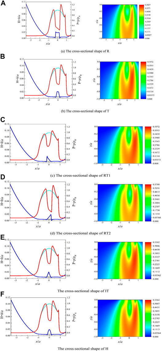
FIGURE 8. The film pressure, film thickness and Von Mises stress distribution with different cross-sectional shape. (A) The cross-sectional shape of R. (B) The cross-sectional shape of T. (C) The cross-sectional shape of RT1. (D) The cross-sectional shape of RT2. (E) The cross-sectional shape of IT. (F) The cross-sectional shape of H.
It can be seen from Figure 8 that the cross-sectional shape of the micro-texture has a significant effect on the film thickness and film pressure in the EHL region. The film thickness in the middle of the EHL contact area of the micro-textured surface is thicker than that of the smooth surface, while the film thickness at other locations of the EHL area is thinner than that of the smooth surface. This result is similar to the film thickness distribution observed by Gao et al. and Wang et al. (Wang and Zhu, 2005; Gao et al., 2010) in point contact. It is worth noting that due to the sudden change of the gap near the outlet position between the two shapes of R and RT2, the film pressure at the outlet position increases more obviously, and the maximum pressure value is greater than those of other shapes, which means that the cross-sectional shape of R and RT2 can be more effectively to restore film pressure.
The film thickness is deemed to be the key parameter that determines the lubrication characteristics. The average film thickness here refers to the average value of the film thickness in the range of 2/3a in the center of the contact area for reduce the error caused by the film thickness at the entrance and exit of the EHL area. Since the micro textures are all designed in the middle of the EHL area, it is appropriate to use the average film thickness. Figure 9 shows the variation of the contact lubrication characteristics with different cross-sectional shapes of different micro-textured sections.
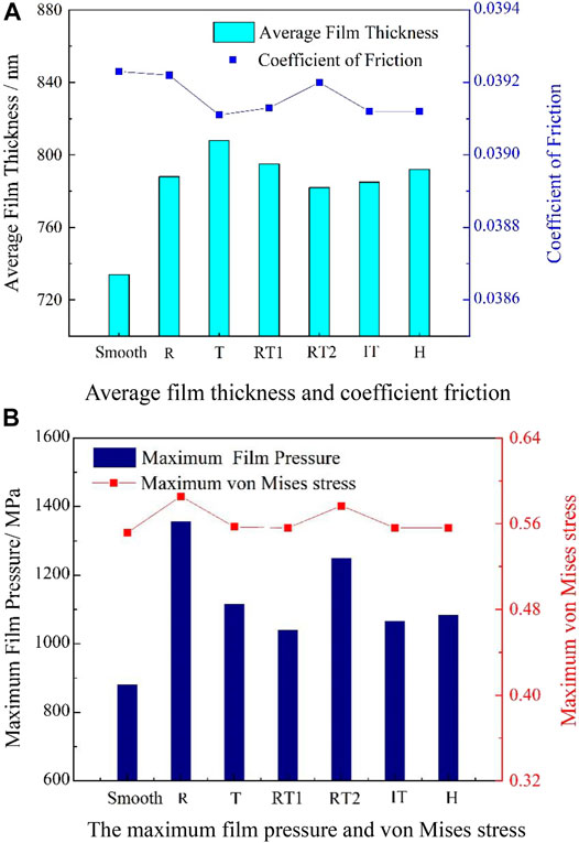
FIGURE 9. Contact lubrication characteristics with different cross-sectional shapes. (A) Average film thickness and coefficient friction. (B) The maximum film pressure and von mises stress.
It can be seen from Figure 9A that the film thickness distribution in the EHL area has a strong correlation with the micro-texture shape. And the average film thickness of all the micro-textures of cross-sectional shapes is thicker than that of the smooth surface, which indicates that although the volume of the concave micro-grains is small, it still has an oil storage effect and can effectively reduce the friction coefficient. It is worth noting that the average film thickness of the cross-sectional shape R and RT2 is smaller than that of T, RT1 and H, and the coefficient of friction is larger. It can be seen from Figure 9B that the maximum film pressure and maximum Von Mises stress of the concave textured surface of all cross-sectional shapes are higher than those of the smooth surface. Furthermore, the maximum film pressure of the two texture shapes of R and RT2 is significantly greater than that of other shapes, which indicated that R and RT2 are conducive to improving the oil film carrying capacity. This result is similar to Nanbu et al.’s conclusion (Nanbu et al., 2008) that short grooves with a small aspect ratio can produce the strongest hydrodynamic lift. For bearings and other parts that need to use micro-textures to improve load-carrying capacity, it is appropriate to choose the texture shapes of R and RT2. And at the same time, the maximum von Mises stress of the two texture shapes of R and RT2 is also slightly greater than that of other shapes, which reduces the contact fatigue strength of contact surface, which indicate that under the current circumstances, there is a contradictory relationship between improving the carrying capacity and reducing friction.
Effect of Micro-texture Diameters on Lubrication Characteristics
In order to analyze the effect of micro-texture diameter on lubrication characteristics, a series of micro-texture diameters (Lx = 8.0–25.0 μm) are designed at a fixed texture depth Lz = 2.5 μm. The groove diagram is shown in Figure 10. Similarly, in order to avoid the influence of the cross-sectional area on the results, the length of the pits in the y direction with different micro-texture diameters is adjusted to meet the requirement of the uniformity of the pit volume. The Lubrication characteristics parameters of film pressure, film thickness and Von Mises stress distribution with different surface texture diameters are shown in Figure 10.
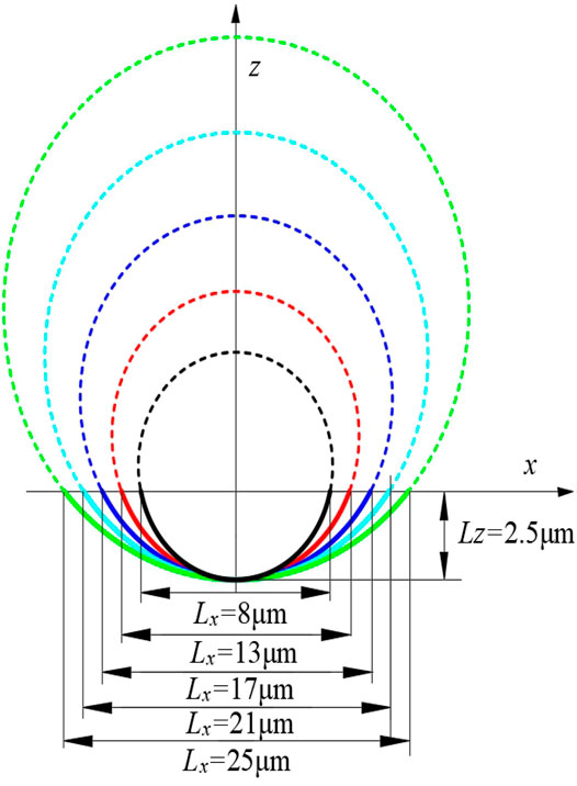
FIGURE 10. Micro-texture of grooves with different diameters.
In Figure 11, the film pressure of micro-textures of all diameters tends to decrease first and then increase, when the micro texture moves to the EHL area. And the film thickness and pressure changes in the local contact area of the EHL area become more obvious as the diameter of the micro-texture increases. Furthermore, as the micro-texture diameter increases, the film pressure in the texture area decreases significantly, while the peak of the membrane pressure at the edge of the texture area becomes larger, which indicted that although the micro-texture stores a part of the lubricant, the other part of the lubricant is squeezed out, which affects the pressure value outside the micro-textured area.
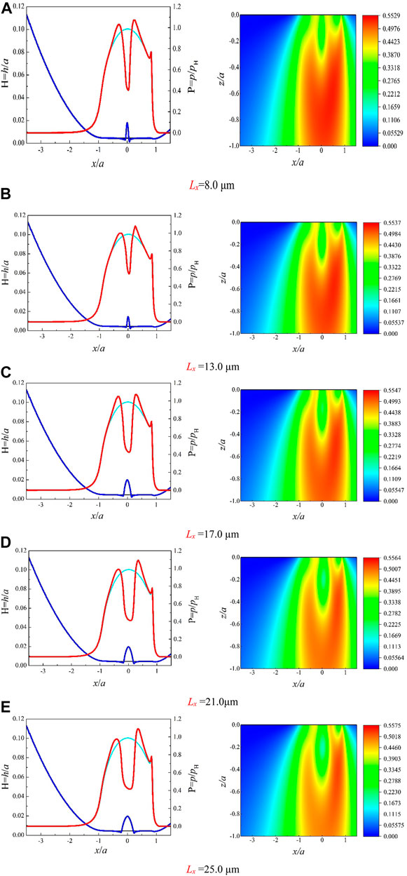
FIGURE 11. The film pressure, film thickness and von Mises stress distribution with different diameters. (A)Lx = 8.0 μm. (B)Lx = 13.0 μm. (C)Lx = 17.0 μm. (d)Lx = 21.0 μm. (E)Lx = 25.0 μm.
Figure 12 shows the contact lubrication characteristics of different micro-texture diameters.
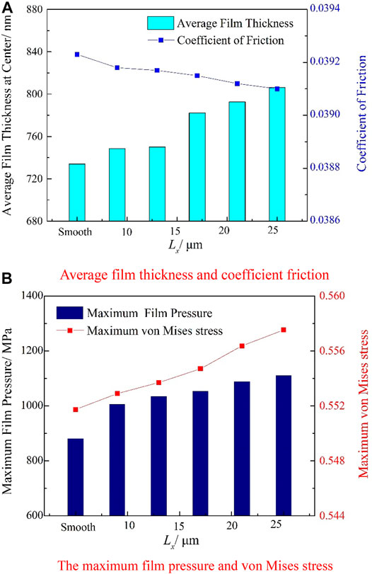
FIGURE 12. Contact lubrication characteristics with different micro-texture diameters. (A) Average film thickness and coefficient friction. (B) The maximum film pressure and von mises stress.
It can be seen from Figure 12A that the average film thickness of micro-textured surfaces of all diameters is larger than that of smooth surfaces and the coefficient of friction of all textures is smaller than that of smooth surfaces, which means that the role of micro-texture storage lubricant can effectively reduce the friction between two contact surfaces. In addition, Figure 12A also shows that the average film thickness is directly proportional to the diameter of the micro-texture, while the friction coefficient is inversely proportional to the diameter of the micro-texture. The variation of the average film thickness and coefficient of friction with the micro-texture diameter is similar to the results observed by Wang et al. (Wang and Zhu, 2005), which indicate that increasing the diameter of the micro-texture is beneficial to improve the lubrication characteristics of the contact surface. It can be seen from Figure 12B that the micro-texture diameter has a greater influence on the contact stress of the surface. When the texture diameter Lx = 8.0 μm, the maximum pressure peak is 1303.80 MPa. When A increases to 25.0 μm, the maximum pressure peak increases by 11.4%, reaching 1463.11 MPa. At the same time, the maximum von Mises stress increases as the micro-texture diameter increases. Accordingly, the contact fatigue life is therefore reduced.
Effect of Micro-texture Depth on Lubrication Characteristics
In this study, the central film thickness at the pitch point is about 0.74 μm. Considering wear and real surface conditions, in this section, a series of depths (Lz = 1.0–3.0 μm) are selected to investigated the lubricating characteristics with a fixed concave texture diameter of 21.0 μm. Figure 13 is a schematic diagram of cross-sections of micro-textures with different depths. Figure 14 shows the results of film pressure, film thickness and von Mises stress distribution with different depths.
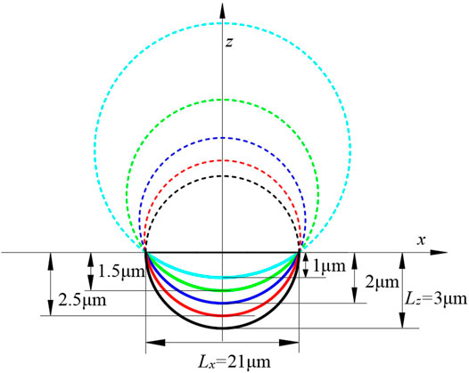
FIGURE 13. Micro-texture of grooves with different depths.
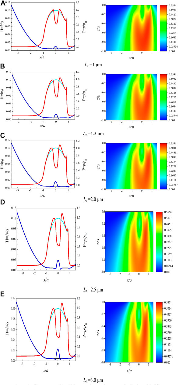
FIGURE 14. The film pressure, film thickness and von Mises stress distribution with different micro-texture depths. (A)Lz = 1 μm. (B)Lz = 1.5 μm. (C)Lz = 2.0 μm. (D)Lz = 2.5 μm. (E)Lz = 3.0 μm.
It can be seen from Figure 14 that as the depth of the micro-texture increases, the central film thickness increases significantly and the depression in the middle of the film pressure becomes more obvious. When the depth of the texture is 1 μm, the central film pressure is 801.5 MPa, and when the depth is increased to 3 μm, the central film pressure is reduced by 38.6%–492.1 MPa.
Figure 15 shows the contact lubrication characteristics of different micro-texture depth.
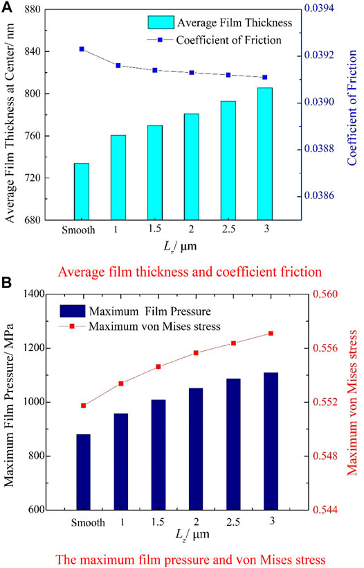
FIGURE 15. contact lubrication characteristics with different micro-texture depth. (A) Average film thickness and coefficient friction. (B) The maximum film pressure and von mises stress.
It can be observed in Figure 15A that the coefficient of friction of the micro-texture with all depths is smaller than that of the smooth surface. The average film thickness in the middle of the contact point is positively correlated with the micro-texture depth, which means that increasing the micro-texture depth can store more oil. On the other hand, as the texture depth increases, the friction coefficient decreases as the texture depth increases, which indicate that increasing the depth can improve the lubrication characteristics. Figure 15B suggests that the development of the micro-texture depth will cause greater irregular impact on the film pressure. The maximum film pressure and maximum von Mises stress of the micro-textured surface are larger than those of the smooth surface, and as the depth of the micro-texture increases, the maximum film pressure and the maximum von Mises stress increase by 18.5 and 0.9% respectively. The maximum film pressure increases from 1232.39 MPa on a smooth surface to 1460.8 MPa with the micro-texture depth is 3 μm, and the maximum Von Mises stress increases from 688.5 MPa on a smooth surface to 695.2 MPa when the micro-texture depth is 3 μm. Although increasing the depth of the micro-texture is beneficial to improve the load bearing capacity of the oil film, since the contact strength and fatigue life of the material are related to the von Mises stress, which means that increasing the depth of the micro-texture will adversely affect the contact fatigue strength and fatigue life of the contact surface.
In general, increasing the micro-texture diameter and depth can improve the lubrication characteristics, but it will cause an increase in von Mises stress at the same time, which is harmful to the contact fatigue life. Therefore, the diameter and depth of micro-texture is not as big as possible. When designing the surface microstructure, numerous factors should be considered, such as the viscosity of the liquid film, the speed of the ring rotation, the local cavitation pressure, the size of the surface microstructure, and so on. Related content will be involved in subsequent research.
Conclusion
The numerical surface reconstruction technology and 3D thermal mixed EHL model are employed to investigate the lubrication characteristics of micro-textured surface. Firstly, a 3D line-contact thermal mixed EHL model is established, and the effectiveness of the model was verified through experiments. Then, the lubrication characteristics of smooth and micro-textured surfaces are discussed. Finally, a series of micro-texture cross-sectional shapes are designed using numerical surface reconstruction technology to investigate the three-dimensional distribution of film pressure, film thickness and von Mises stress of different micro-texture cross-sections, micro-texture diameters and depths.
(1) Compared with the smooth surface, the film thickness in the EHL central region of the micro-textured surface increases, while the film pressure, meanwhile, there will be obvious pressure peaks at both ends of the micro-texture.
(2) The comparison of the film thickness under the conditions used in this study shows that the average oil film thickness of the shapes T, RT1 and H is larger than other shapes, and the friction coefficient is smaller than other shapes, while the shapes R and RT2 are beneficial for improving the bearing capacity.
(3) The average film thickness between the surfaces can be increased by increasing the diameter and depth of the micro-texture within a certain range, while the lubrication characteristics are improved.
Data Availability Statement
The original contributions presented in the study are included in the article/Supplementary Material, further inquiries can be directed to the corresponding author.
Author Contributions
JZ revised the original idea, designed the research plan, analyzed the results and wrote the manuscript, ZL designed the test plan and analyzed the test results, HZ participated in the drafting of the manuscript and proposed some revisions, RZ proposed the original idea of the study.
Funding
This work was supported by the National Key R and D Program of China (Grant No. 2018YFB2001300), the National Natural Science Foundation of China (Grant No. 51775264) and the National Defense Basic Research Program (Grant No. JCKY2019605D003).
Conflict of Interest
The authors declare that the research was conducted in the absence of any commercial or financial relationships that could be construed as a potential conflict of interest.
Acknowledgments
The authors would like to thank the reviewers for their very valuable comments.
References
Ali, F., Kaneta, M., Křupka, I., and Hartl, M. (2015). Experimental and Numerical Investigation on the Behavior of Transverse Limited Micro-grooves in EHL Point Contacts. Tribol. Int. 84, 81–89. doi:10.1016/j.triboint.2014.11.025
Chen, W. W., Liu, S., and Wang, Q. J. (2008). Fast Fourier Transform Based Numerical Methods for Elasto-Plastic Contacts of Nominally Flat Surfaces. J. Appl. Mech. 75. doi:10.1115/1.2755158
Codrignani, A., Savio, D., Pastewka, L., Frohnapfel, B., and van Ostayen, R. (2020). Optimization of Surface Textures in Hydrodynamic Lubrication through the Adjoint Method. Tribol. Int. 148, 106352. doi:10.1016/j.triboint.2020.106352
Gachot, C., Rosenkranz, A., Hsu, S. M., and Costa, H. L. (2017). A Critical Assessment of Surface Texturing for Friction and Wear Improvement. Wear 372-373, 21–41. doi:10.1016/j.wear.2016.11.020
Gachot, C., Rosenkranz, A., Reinert, L., Ramos-Moore, E., Souza, N., Müser, M. H., et al. (2013). Dry Friction between Laser-Patterned Surfaces: Role of Alignment, Structural Wavelength and Surface Chemistry. Tribol. Lett. 49, 193–202. doi:10.1007/s11249-012-0057-y
Gadeschi, G. B., Backhaus, K., and Knoll, G. (2012). Numerical Analysis of Laser-Textured Piston-Rings in the Hydrodynamic Lubrication Regime. J. Tribol. 134, 041702. doi:10.1115/1.4007347
Gao, L., Yang, P., Dymond, I., Fisher, J., and Jin, Z. (2010). Effect of Surface Texturing on the Elastohydrodynamic Lubrication Analysis of Metal-On-Metal Hip Implants. Tribol. Int. 43, 1851–1860. doi:10.1016/j.triboint.2010.02.006
Gropper, D., Wang, L., and Harvey, T. J. (2016). Hydrodynamic Lubrication of Textured Surfaces: A Review of Modeling Techniques and Key Findings. Tribol. Int. 94, 509–529. doi:10.1016/j.triboint.2015.10.009
Ito, S., Takahashi, K., and Sasaki, S. (2020). Generation Mechanism of Friction Anisotropy by Surface Texturing under Boundary Lubrication. Tribol. Int. 149, 105598. doi:10.1016/j.triboint.2019.02.006
Jadhav, S., Thakre, G. D., and Sharma, S. C. (2019). Influence of MHD Lubrication and Textured Surface in EHL Line Contact. Front. Mech. Eng. 5, 33. doi:10.3389/fmech.2019.00033
Khaemba, D. N., Azam, A., See, T., Neville, A., and Salehi, F. M. (2020). Understanding the Role of Surface Textures in Improving the Performance of Boundary Additives, Part I: Experimental. Tribol. Int. 146, 106243. doi:10.1016/j.triboint.2020.106243
Kovalchenko, A., Ajayi, O., Erdemir, A., Fenske, G., and Etsion, I. (2004). The Effect of Laser Texturing of Steel Surfaces and Speed-Load Parameters on the Transition of Lubrication Regime from Boundary to Hydrodynamic. Tribol. Trans. 47, 299–307. doi:10.1080/05698190490440902
Liu, S., Wang, Q., and Liu, G. (2000). A Versatile Method of Discrete Convolution and FFT (DC-FFT) for Contact Analyses. Wear 243, 101–111. doi:10.1016/S0043-1648(00)00427-0
Liu, S., and Wang, Q. (2002). Studying Contact Stress Fields Caused by Surface Tractions with a Discrete Convolution and Fast Fourier Transform Algorithm. J. Tribol.-Trans. Asme. 124, 36–45. doi:10.1115/1.1401017
Marian, M., Grützmacher, P., Rosenkranz, A., Tremmel, S., Mücklich, F., and Wartzack, S. (2019). Designing Surface Textures for EHL Point-Contacts - Transient 3D Simulations, Meta-Modeling and Experimental Validation. Tribol. Int. 137, 152–163. doi:10.1016/j.triboint.2019.03.052
Nanbu, T., Ren, N., Yasuda, Y., Zhu, D., and Wang, Q. J. (2008). Micro-Textures in Concentrated Conformal-Contact Lubrication: Effects of Texture Bottom Shape and Surface Relative Motion. Tribol. Lett. 29, 241–252. doi:10.1007/s11249-008-9302-9
Pettersson, U., and Jacobson, S. (2004). Friction and Wear Properties of Micro Textured DLC Coated Surfaces in Boundary Lubricated Sliding. Tribol. Lett. 17, 553–559. doi:10.1023/B:TRIL.0000044504.76164.4e
Ren, N., Zhu, D., Chen, W. W., Liu, Y., and Wang, Q. J. (2009). A Three-Dimensional Deterministic Model for Rough Surface Line-Contact EHL Problems. J. Tribol.-Trans. Asme. 131. doi:10.1115/1.2991291
Rosenkranz, A., Szurdak, A., Gachot, C., Hirt, G., and Mücklicha, F. J. (2016). Friction reduction under mixed and full film EHL induced by hot micro-coined surface patterns. Tribol. Int. 95. 290–297. doi:10.1016/j.triboint.2015.11.035
Shi, X., Sun, W., Lu, X., Ma, X., Zhu, D., Zhao, B., et al. (2019). Three-dimensional Mixed Lubrication Analysis of Spur Gears with Machined Roughness. Tribol. Int. 140, 105864. doi:10.1016/j.triboint.2019.105864
Taee, M., Torabi, A., Akbarzadeh, S., Khonsari, M. M., and Badrossamay, M. (2017). On the Performance of EHL Contacts with Textured Surfaces. Tribol. Lett. 65, 85. doi:10.1007/s11249-017-0871-3
Vlădescu, S-C., Medina, S., Olver, A. V., et al. (2016). Lubricant Film Thickness and Friction Force Measurements in a Laser Surface Textured Reciprocating Line Contact Simulating the Piston Ring–Liner Pairing. Tribol. Int. 98, 317–329. doi:10.1016/j.triboint.2016.02.026
Wang, L. (2014). Use of Structured Surfaces for Friction and Wear Control on Bearing Surfaces. Surf. Topogr.: Metrol. Prop. 2, 043001. doi:10.1088/2051-672x/2/4/043001
Wang, Q. J., and Zhu, D. (2005). Virtual Texturing: Modeling the Performance of Lubricated Contacts of Engineered Surfaces. J. Tribol. 127, 722–728. doi:10.1115/1.2000273
Wang, W.-Z., Wang, H., Liu, Y.-C., Hu, Y.-Z., and Zhu, D. (2003). A Comparative Study of the Methods for Calculation of Surface Elastic Deformation. Proc. Inst. Mech. Eng. J: J. Eng. Tribol. 217, 145–154. doi:10.1243/13506500360603570
Wang, W.-Z., Wang, S., Shi, F., Wang, Y.-C., Chen, H.-B., Wang, H., et al. (2007). Simulations and Measurements of Sliding Friction between Rough Surfaces in Point Contacts: From EHL to Boundary Lubrication. J. Tribol. 129, 495–501. doi:10.1115/1.2736432
Woloszynski, T., Podsiadlo, P., and Stachowiak, G. W. (2014). Evaluation of Discretization and Integration Methods for the Analysis of Finite Hydrodynamic Bearings with Surface Texturing. Proc. Inst. Mech. Eng. Part J: J. Eng. Tribol. 229, 465–477. doi:10.1177/1350650114544711
Wu, Z., Xing, Y., Huang, P., and Liu, L. (2017). Tribological Properties of Dimple-Textured Titanium Alloys under Dry Sliding Contact. Surf. Coat. Technol. 309, 21–28. doi:10.1016/j.surfcoat.2016.11.045
Yan, X.-L., Wang, X.-L., and Zhang, Y.-Y. (2013). A Parametric Study on Fatigue Life for Mixed Elastohydrodynamic Lubrication Point Contacts. J. Tribol. 135, 041501. doi:10.1115/1.4024303
Yan, X.-L., Wang, X.-L., and Zhang, Y.-Y. (2014). Influence of Roughness Parameters Skewness and Kurtosis on Fatigue Life under Mixed Elastohydrodynamic Lubrication Point Contacts. J. Tribol. 136, 031503. doi:10.1115/1.4027480
Yang, Y., Li, W., Wang, J., and Zhou, Q. (2019). On the Mixed EHL Characteristics, Friction and Flash Temperature in Helical Gears with Consideration of 3D Surface Roughness. Ilt 71, 10–21. doi:10.1108/ILT-04-2017-0113
Yu, T. H., and Sadeghi, F. (2001). Thermal Effects in Thrust Washer Lubrication. J. Tribol. 124, 166–177. doi:10.1115/1.1399053
Yuan, S., Huang, W., and Wang, X. (2011). Orientation Effects of Micro-grooves on Sliding Surfaces. Tribol. Int. 44, 1047–1054. doi:10.1016/j.triboint.2011.04.007
Zhu, D., and Cheng, H. S. (1989). An Analysis and Computational Procedure for EHL Film Thickness, Friction and Flash Temperature in Line and Point Contacts. Tribol. Trans. 32, 364–370. doi:10.1080/10402008908981901
Zhu, D., Liu, Y., and Wang, Q. (2014). On the Numerical Accuracy of Rough Surface EHL Solution. Tribol. Trans. 57, 570–580. doi:10.1080/10402004.2014.886349
Zhu, D. (2007). On Some Aspects of Numerical Solutions of Thin-Film and Mixed Elastohydrodynamic Lubrication. Proc. Inst. Mech. Eng. Part J: J. Eng. Tribol. 221, 561–579. doi:10.1243/13506501JET259
Keywords: micro-texture, thermal EHL, lubrication characteristics, contact stress, line contact
Citation: Zhao J, Li Z, Zhang H and Zhu R (2021) Prediction of Contact and Lubrication Characteristics of Micro-textured Surface Under Thermal Line Contact EHL. Front. Mech. Eng 7:672588. doi: 10.3389/fmech.2021.672588
Received: 26 February 2021; Accepted: 03 May 2021;
Published: 13 May 2021.
Edited by:
Soumyadip Sett, University of Illinois at Urbana-Champaign, United StatesReviewed by:
Varun Kulkarni, University of Illinois at Chicago, United StatesT V V L N Rao, Madanapalle Institute of Technology and Science (MITS), India
Copyright © 2021 Zhao, Li, Zhang and Zhu. This is an open-access article distributed under the terms of the Creative Commons Attribution License (CC BY). The use, distribution or reproduction in other forums is permitted, provided the original author(s) and the copyright owner(s) are credited and that the original publication in this journal is cited, in accordance with accepted academic practice. No use, distribution or reproduction is permitted which does not comply with these terms.
*Correspondence: Zhengminqing Li, lzmq_cmee@nuaa.edu.cn