Drop-On-Demand Lubrication of Gears: A Feasibility Study
 M. Mirza1
  T. Lohner
 C. H. Venner
- 1Gear Research Centre (FZG), Department of Mechanical Engineering, School of Engineering and Design, Technical University of Munich, Munich, Germany
- 2Engineering Fluid Dynamics Group, University of Twente, Enschede, Netherlands
Different lubrication methods such as oil dip or injection lubrication are used in gearboxes to lubricate tribological contacts and to dissipate frictional heat. To improve resource and energy efficiency, novel needs-based lubrication methods like the drop-on-demand lubrication are being developed. It includes an ink-jet nozzle driven by a piezo element to generate picoliter droplets injected to tribological contacts. This study evaluates the feasibility of drop-on-demand lubrication of gears. Friction measurements in rolling-sliding contacts indicate the formation of typical elastohydrodynamic contacts. Power loss measurements of gears show a similar behavior compared to continuous minimum quantity lubrication. Hence, the study confirms that the operation of gears with drop-on-demand lubrication is possible. It introduces the possibility of dynamic and flexible oil supply on a contact needs-based level.
Introduction
The selection of a gearbox lubrication method depends on several factors. Gearboxes with relevant power transmission are generally lubricated by grease or oil. The thereby involved lubricant amounts can be large. The interaction of fluid lubricants with rotating machine elements results in fluid flow and inner friction and hence, in no-load power losses approximately independent of the transmitted load. Hinterstoißer et al. (2019) (Hinterstoißer, 2014) conducted experiments at a gear efficiency back-to-back test rig and showed for oil dip lubrication a significant increase in no-load power losses with increasing circumferential speed. By decreasing the immersion depth from 21 mm at the pinion to 11 mm at the wheel with a corresponding reduction in the oil volume, the no-load power losses decreased by up to 30% at high circumferential speed. Leaving aside other power losses by oil pumps, for example, oil injection lubrication can reduce no-load power losses compared to oil dip lubrication. Doleschel (2003) (Doleschel et al., 2002), Moss et al. (2018) and Andersson et al. (2017) showed a decrease of no-load power losses up to 34% for continuous oil injection lubrication, especially at high circumferential speed. Otto (2009) and Höhn et al. (2009) further reduced the no-load power loss by continuous minimum quantity lubrication (MQL) using a continuous air stream as transporting fluid for very small oil quantities supplied to the gear mesh with flow rates between 3.5 and 108 mL/h.
Such results with continuous MQL prove that the required lubricant amount for lubrication of tribological contacts in gearboxes is small. However, the lubricant amount required for dissipation of frictional heat under power transmission can be large. Hinterstoißer et al. (2019) (Hinterstoißer, 2014) showed an increasing gear bulk temperature with decreasing oil immersion depth for a dip-lubricated gearbox. Otto (2009) observed for a continuous injection-lubricated gearbox a notable increase of the gear bulk temperature with decreasing injection volume. In order to avoid thermal load limits of gearboxes even when the lubricant amount is reduced, load-dependent power losses can be reduced. Hinterstoißer et al. (2019) (Hinterstoißer, 2014) showed that load-dependent gear power losses decrease from mineral to polyalphaolefin to polyglycol to polyether oils. Thereby, a maximum reduction in the mean gear coefficient of friction up to 62% is possible for polyether oils. A further decrease in the load-dependent gear power losses is presented by Yilmaz et al. (2019a), Yilmaz et al. (2019b) and Yilmaz et al. (2020) with water-containing gear lubricants achieving superlubricity. Besides low-friction lubricants, low-loss gear designs, superfinishing of tooth flanks and coatings are measures for reducing load-dependent power losses, e.g., De Barros Bouchet et al. (2007), Björling et al. (2014), Bobzin et al. (2015), De Barros Bouchet et al. (2017) and Kuwahara et al. (2019).
For gearboxes with small load-dependent power losses, the lubricant amount and supply to tribological contacts in machine elements can be drastically reduced. For rolling-sliding contacts, Ebner et al. (2018a) investigated one-time MQL at a twin-disk tribometer and showed significant lower friction and longer lifetime compared to dry lubrication. Compared to oil injection lubrication, the measured friction was similar for polished surfaces and higher for rough surfaces. Bobzin et al. (2019), Bobzin et al. (2020a) and Bobzin et al. (2020b)) considered (Cr,Al)N and (Cr,Al,Mo)N coated surfaces for one-time MQL and showed lower friction and higher operation stability compared to uncoated surfaces. Ebner et al. (2017), Ebner et al. (2018b) and Omasta et al. (2018) investigated rolling-sliding contacts with intrinsic self-lubrication provided by oil-impregnated sintered steels. No extrinsic oil supply is required, but the lubricant film formed in elastohydrodynamically lubricated (EHL) contacts is thinner compared to conventional steel.
EHL contacts with minimal oil supply may operate in starved conditions. Since the early works of Wedeven et al. (1971) and Pemberton and Cameron (1976), this regime has been studied extensively, experimentally and can be predicted quite accurately theoretically, both under steady and transient conditions, e.g., see Chevalier et al. (1998), Damiens et al. (2004), Wijnant and Venner (1999), Venner et al. (2003) and Venner et al. (2008). This work culminated in the thin-layer lubrication models of Van Zoelen et al. (2009) and Van Zoelen et al. (2010). The studies showed that starved contacts are very efficient from a lubrication point of view. A steady state circular EHL contact only needs a layer of oil in the contact inlet that is about twice the central film thickness under fully flooded conditions to achieve a film thickness as for fully flooded conditions. This is because under fully flooded conditions most of the lubricant flows around the contact zone. Under starved conditions, this inlet side flow is virtually absent, increasingly so for wide elliptic contacts, and even though the lubricant film itself may be thinner, at least all the lubricant supplied to the contact is actually used for surface separation. With the present capability of numerical modelling and algorithms, detailed effects of minimal lubrication methods can be predicted.
A lubrication method with minimized oil supply to tribological contacts is the Drop-on-Demand (DoD) lubrication. Van der Kruk et al. (2019) developed a DoD printing system with an ink-jet nozzle driven by a piezo element that is able to generate droplets of picoliter scale. For an oil conditioned at a temperature where the viscosity is 46 mPas, generation of droplets with a volume of 3.3 pL is possible. It can be supplied to rolling contacts at a controlled frequency to form an EHL contact. Experiments with an optical tribometer and numerical modelling showed film thickness evolution over time from dry to fully flooded with a total oil usage of approximately 40 nL. DoD lubrication makes it possible to provide the amount of lubricant to the EHL contact exactly as required. Numerical results illustrate in great detail droplet spreading and ingestion into the EHL contact and accurately predict lubricant film formation in the contact over time, see Figure 1.
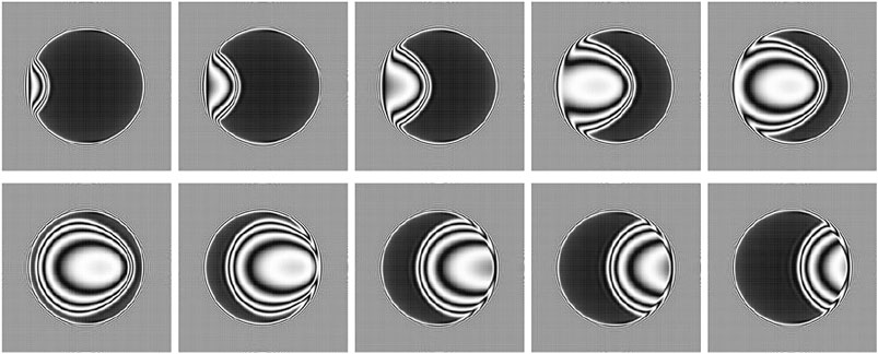
FIGURE 1. Pseudo-interferograms of the calculated (dimensionless) film thickness in a circular EHL contact at different times during ingestion of a droplet (top row from left to right, followed by bottom row from left to right) (van der Kruk et al., 2019).
Sensor systems enable condition monitoring of gearbox machine elements, e.g. Chin et al. (2021), Fromberger et al. (2019) and Touret et al. (2018). It can be applied to prevent damages, detect early damage and increase efficiency. Thin-film sensors enable the in-situ measurement of physical variables in tribological contacts such as temperature or pressure (Albahrani et al., 2016). The electrical contact resistance measurement technique is a method to evaluate the lubrication regime of tribological contacts and was applied by, e.g., Lugt et al. (2001), Kleemola and Lehtovaara (2010), Glovnea et al. (2012), Liu et al. (2016) and Clarke et al. (2016).
DoD lubrication can be seen as MQL on a needs-based contact level. DoD lubrication has a high potential to improve lubrication of gearboxes from a resource and energy efficiency point of view, particularly when associated with sensors to monitor the condition of tribosystems. This study evaluates the feasibility of DoD lubrication in rolling-sliding contacts of gears. Experimental investigations are conducted at a twin-disk tribometer and at a gear test rig to analyze the power loss and thermal behavior. Contact resistance is recorded to evaluate the lubrication regime.
Experimental Method
In this section the twin-disk tribometer and gear test rig as well as the test parts, operating conditions, the DoD printing system and the contact resistance measurement are described.
Twin-Disk Tribometer
Twin-disk tribometers are often used for basic investigations on rolling-sliding contacts of gears. Good transferability of friction behavior on gears is known (Mayer, 2013; Hinterstoißer, 2014).
Mechanical Setup
Figure 2 shows the mechanical layout of the considered FZG twin-disk tribometer. The following short description is based on Ebner et al. (2018a) and Yilmaz et al. (2019a).
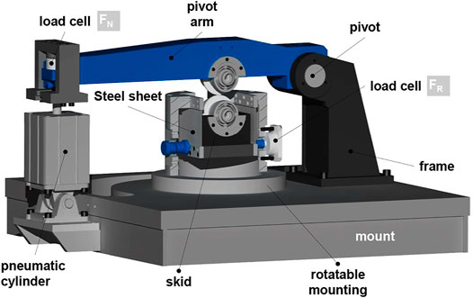
FIGURE 2. Mechanical layout of the considered FZG twin-disk tribometer (Ebner et al., 2018a).
The test disks are press-fitted onto shafts, which can be driven independently by two speed-controlled electric motors. This allows the continuous variation of the speed. The normal force FN on the disk contact is applied by a pneumatic cylinder via the pivot arm where the upper disk is mounted. The lower disk is mounted in a skid, which is attached to the frame by thin steel sheets. The skid is supported by a load cell so that the friction force FR in the disk contact for sliding velocities vg ≠ 0 m/s can be measured as reaction force with hardly any displacement of the skid. The coefficient of friction µ is calculated from the recorded forces according to Eq. 1.
Normal force FN, friction force FR, surface velocities v1 and v2 and bulk temperature of the upper disk ϑM are measured. ϑM is recorded by a Pt100 resistance temperature sensor inside the disk 5 mm below the surface. Sum velocity vΣ is defined as the sum of the surface velocity of the lower disk v1 and the upper disk v2. Sliding velocity vg is defined as the difference between surface velocities v1 and v2 with v1 > v2:
Slip ratio s is defined as:
Test Disks
The disks used are cylindrical with a diameter of 80 mm and a width of 5 mm (Figure 3, left). Hence, a line contact is formed. To ensure a uniform load distribution over the disk width, a contact print on aluminum foil is evaluated prior to each test. Any misalignment is carefully corrected mechanically. The disks are made of case-carburized steel 16MnCr5 (AISI 5115) with a surface hardness of 690–740 HV1 and case-hardening depth of CHD550HV1 = 0.9 + 0.2 mm. The running surfaces of the test disks are axially ground and superfinished to an arithmetic mean roughness of Ra ≈ 0.05 µm (Figure 3, right). The surface roughness measurements are performed with a stylus instrument perpendicular to the grinding direction in the middle of the disk. The profile method is used with a measurement length of Lt = 4.8 mm and a cut-off wavelength λc = 0.8 mm.
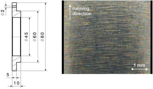
FIGURE 3. Test disk geometry (left) and light microscope picture of the running surface before test run (right).
Operating Conditions
Table 1 shows the operating conditions considered for the twin-disk experiments. Two loads with FN = {980, 3920} N are considered, which correspond to Hertzian pressures of pH = {600, 1200} N/mm2. For each load, three sum velocities vΣ = {2, 4, 8} m/s are investigated. By increasing the slip ratio s from 0% to 50% per load and sum velocity, a friction curve is recorded. The coefficient of friction and bulk temperature are measured as quasi-stationary values, i.e., when the change in bulk temperature ΔϑM/Δt is smaller than 0.5 K/min. A running-in is conducted for 30 min at pH = 1200 N/mm2, vΣ = 1 m/s and s = 20%. Each friction curve is repeated once. Measurements are aborted when the measured disk bulk temperature ϑM exceeds 160°C due to the initiated annealing effects in AISI 5115. Before the experiments, the running surface of the disks are wetted with a minimum quantity of oil in order to avoid failures during start-up Ebner et al. (2018a). The DoD oil supply is explained in Drop-On-Demand Oil Supply.
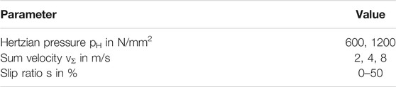
TABLE 1. Operating conditions at the twin-disk tribometer.
Gear Efficiency Test Rig
The FZG gear efficiency test rig is used to evaluate the power loss and temperature behavior of DoD lubricated gears.
Mechanical Setup
Figure 4 shows the mechanical layout of the FZG gear efficiency test rig in back-to-back configuration with a center distance of 91.5 mm. The main features of the test rig are described based on Schwarz et al. (2020) and Yilmaz et al. (2019b). For details, the reader is also referred to Hinterstoißer (2014).
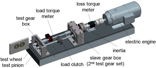
FIGURE 4. Mechanical layout of the FZG gear efficiency test rig (Lohner, 2016).
The FZG gear efficiency test rig is based on the concept of power circulation. The transmitted torque load is applied by a load clutch and measured by a torque meter. The total loss torque is measured by a torque meter shaft mounted between the electric motor and the wheel shaft of the power circle. The shaft speeds, the pinion bulk temperature, the load and loss torque are measured. All pinion and gear shafts are supported by cylindrical roller bearings of the type NU406 and NJ406 made of ceramic cylindrical rollers, Cronidur© races and a polyether ether ketone (PEEK) cage. Radial shaft seals made of Viton are used. Total loss of the power circle PL consists of load-dependent gear loss PLGP, no-load gear loss PLG0, load-dependent bearing loss PLBP, no-load bearing loss PLB0 and sealing loss PLS:
When applying a negligible load torque to the load clutch in the power circle, measured total loss PL corresponds to the sum of the no-load losses. Load-dependent bearing loss PLBP are calculated according to SKF14 (SKF, 2014). Load-dependent gear loss PLGP is then determined by subtracting the sum of the no-load losses and load-dependent bearing loss PLBP from measured total loss PL. Since the test gearboxes have the same gear pairs, the measured loss can be approximately halved to obtain the load-dependent gear loss of one gearbox. This load-dependent gear loss PLGP is the integral of the local distribution of the gear power loss across the area of contact:
Test Gears
The FZG test spur gear of type Cmod made of case-carburized steel 16MnCr5E (AISI 5115) is considered. Hence, a line contact as at the twin-disk tribometer is formed. The main gear parameters are shown in Table 2. All gear flanks are ground and superfinished to an arithmetic mean roughness Ra = 0.14 ± 0.03 µm. The surface roughness measurements are performed with a stylus instrument in involute direction perpendicular to the grinding direction. As for disks, the profile method is used with a measurement length of Lt = 4.8 mm and a cut-off wavelength λc = 0.8 mm.
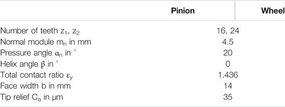
TABLE 2. Main gear parameters of test gear of type Cmod.
Operating Conditions
Figure 5 shows a schematic of the experimental test order at the FZG gear test rig, which has similarities to the standard test of Doleschel et al. (2002) (Doleschel, 2003). The test order is arranged from no-load to high load specified by the Hertzian pressure at the pitch point pC. Table 3 relates pinion torque T1 and wheel torque T2 to pC. First, a run-in at pC = 1343 N/mm2 and vt = 0.5 m/s is performed for 30 min. Then four pitch line velocities vt = {0.5, 2.0, 5.0, 8.3} m/s are investigated consecutively for each Hertzian pressure pC. The housing temperature is controlled at 60°C. Each operating condition is held for 5 min. All tests are repeated once. A test is aborted when the tooth bulk temperature ϑM1 exceeds 160°C, due to the initiated annealing effects in AISI 5115. Before the experiments, the tooth flanks of the gears and the bearings are wetted with a minimum quantity of oil in order to avoid failures during start-up (Ebner et al., 2018a). The DoD oil supply is explained in Drop-On-Demand Oil Supply.
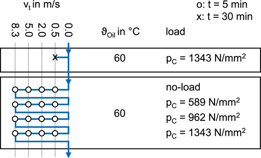
FIGURE 5. Experimental test order at the gear efficiency test rig.
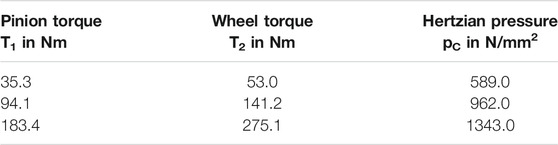
TABLE 3. Investigated pinion torques, wheel torques and Hertzian pressures at the gear efficiency test rig.
Drop-On-Demand Oil Supply
The DoD oil supply system used is the same as in the work of van der Kruk et al. (2019). The conditions for successful droplet formation can be quantified in terms of the Reynolds number Re, the Weber number We and the Ohnesorge number Oh. Reis and Derby (2000) formulated a condition 0.1 < Oh < 1 respectively for single droplet ejection. Duineveld et al. (2002) developed an expression for the minimum velocity based on We > 4. Stow et al. derived a splashing condition, We0.5Re0.25 < 50. For further information on droplet formation, the reader is referred to Derby (2010).
A Microdrop MD-K-140 70 μm heated tip piezo driven dispenser is used. The dispenser head tip temperature is set and regulated using a Microdrop MD-E-3011 control unit. The electric pulse to drive the dispenser head piezo element is generated using an ISO-TECH AFG-21225 arbitrary waveform generator and is amplified using a Falco Systems WMA-300 static amplifier. By varying the pulse width, pulse amplitude and dispenser head temperature, the droplet size and inflight velocity can be influenced. The final settings for the waveform used include a tandem pulse signal with a maximum absolute amplitude of 248 V, starting with a positive push pulse (+124 V) of 72 μs, followed by a pause (0 V) of 18 μs and concluding with a negative pull pulse (-124 V) of 9 μs. According to Chen and Basaran (2002) this push pull effect yields smaller droplets at a given nozzle diameter. By regulating the dispenser head tip temperature at 70°C and using the tandem pulse as discussed, droplets were generated with a diameter of 74.4 μm (216 pL) ejected at a speed of 1.92 m/s.
The dispenser head is positioned at the twin-disk tribometer, as depicted in Figure 6 (top). Droplets are ejected onto the upper disk before being transported into the disk contact. At the gear test rig, the dispenser head is positioned straight above the pinion, as depicted in Figure 6 (bottom). The counter-clockwise rotation of the pinion transports the droplets into the gear contact.
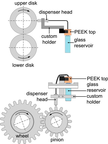
FIGURE 6. Implementation of the drop-on-demand printing system at the twin-disk tribometer (top) and gear test rig (bottom).
For the experiments at the twin-disk tribometer a constant droplet frequency of fDoD = 2500 Hz resulting in a mean injection flow rate of
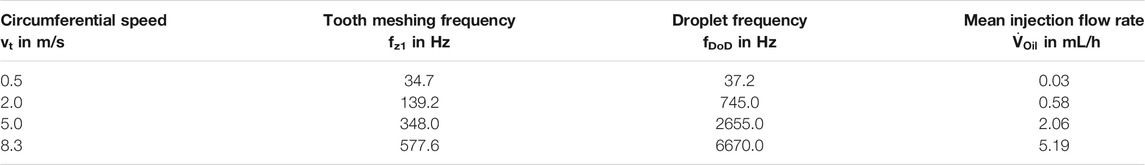
TABLE 4. Tooth meshing frequency of pinion fz1, droplet frequency fDoD and resulting mean injection flow rate
Lubricant
Shell High Viscosity Index 60 (Shell HVI 60) paraffinic mineral oil is used. Table 5 shows the main lubricant properties. More information can be found at van der Kruk et al. (2019) and Shell Chemicals (2017).

TABLE 5. Main lubricant properties of Shell HVI 60 (van der Kruk et al., 2019)
Contact Resistance Measurement
The electrical contact resistance in the lubricated contact is used for the qualitative evaluation of the lubrication regime, see Furey and Appeldoorn (1962), Kleemola and Lehtovaara (2010), Wimmer (2006), and Clarke et al. (2016). Depending on the lubricant film thickness and the roughness of the contacting surfaces, a certain amount of solid contact can occur. Contact areas with solid or rather metallic contact show conducting behavior, whereas contact areas separated by an oil film or covered with insulating tribofilms are electrically insulating. Thus, the electrical current flowing through the contact is constricted to areas of metallic asperity contact, meaning that constriction resistance can occur.
The principle of electrical contact resistance in tribosystems is shown in Figure 7 (left). The electrical setup is a circuit based on a Wheatstone bridge with an additional input resistance to limit the maximum current and a potentiometer for zero-point adjustment, see Figure 7 (right). An input voltage of U0 = 800 mV is chosen as it is sufficiently low to avoid electrical breakdown and sufficiently high to allow accurate measurement results. It is important to note that the measured voltage U is referred to the contact voltage and not to the voltage UC that is actually present at the tribological contact. U corresponds non-linearly to the contact resistance.
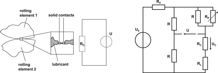
FIGURE 7. Principle of electrical contact resistance measurement in tribological contact (left) and circuit diagram of measurement setup (right).
The rolling elements have to be insulated from the shafts to prevent influence of parasitic electrical conductivity. This is ensured by ceramic spacer sleeves and bushings between the rolling elements and the connecting surfaces.
Since insulating tribofilms impact the results of electrical contact resistance measurement, the method shows some limitations when lubricants with surface-active additives are used. The considered lubricant contains no particular surface-active additives. Additionally, the size of the flattened area of the EHL contact and the overlap ratio of gears influence the measured contact resistance. As different loads are considered at the twin-disk tribometer and gear test rig, the flattened area varies. For the considered test gear, the overlap ratio is constant but the load and geometry as well as the number of teeth in contact vary during gear mesh. Hence, the measured contact resistance corresponds to a time-averaged value of the time-dependent system. In this study, no compensation of geometrical effects is made so that a direct comparison of different loads is limited. The focus of this feasibility study for DoD lubrication is the uncompensated measured voltage U.
Results and Discussion
In the following, the experimental results from the twin-disk tribometer and gear efficiency test rig are presented and discussed.
Experiments at Twin-Disk Tribometer
Figure 8 and Figure 9 show measured coefficients of friction µ, bulk temperatures ϑM and contact voltages U at the twin-disk tribometer in quasi-stationary condition. Figure 8 refers to pH = 600 N/mm2 and Figure 9 to pH = 1200 N/mm2. In each diagram the results of the first and second test run are shown over slip ratio s for vΣ = {2, 4, 8} m/s. The DoD lubrication method is used as described in Drop-On-Demand Oil Supply.
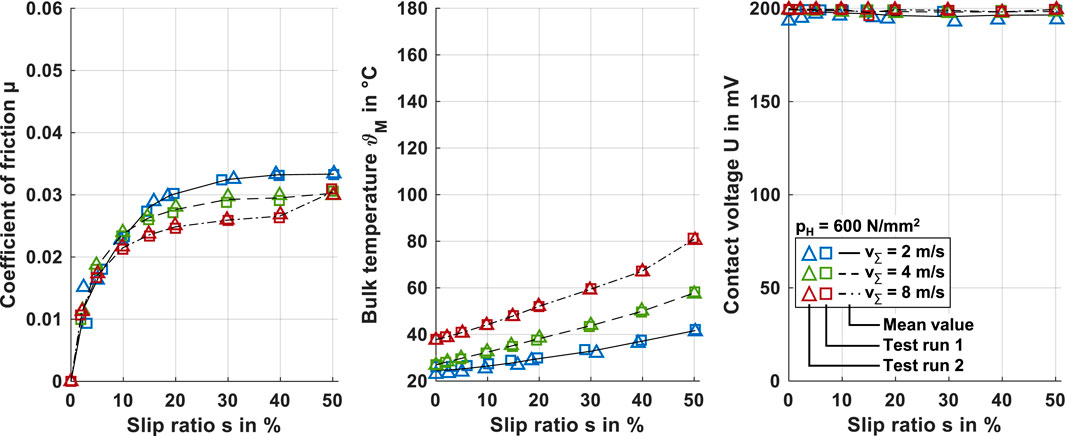
FIGURE 8. Measured coefficients of friction μ, bulk temperatures ϑM and contact voltages U over slip ratio s for pH = 600 N/mm2 and vΣ = {2, 4, 8} m/s under DoD lubrication at the twin-disk tribometer.
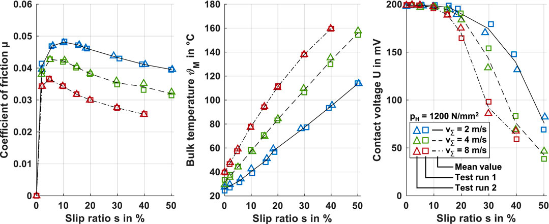
FIGURE 9. Measured coefficients of friction µ, bulk temperatures ϑM and contact voltages U over slip ratio s for pH = 1200 N/mm2 and vΣ = {2, 4, 8} m/s under DoD lubrication at the twin-disk tribometer.
For pH = 600 N/mm2 (Figure 8), a steady increase of the coefficient of friction (left) with increasing slip ratio is observed. For very low slip ratio the friction curves increase sharply, before they increase digressively for higher slip ratio. This is typical for low-loaded EHL contacts and can be related to shear-thinning and thermal effects. The thermal effects get more pronounced with increasing sum velocity as the effective contact viscosity related to higher bulk and contact temperatures decreases. For vΣ = 8 m/s and s = 50%, a slight increase in the coefficient of friction can be observed. The measured bulk temperature (middle) is related to the frictional contact heat, which increases with increasing slip ratio and sum velocity. The contact voltage (right) shows almost constant values of U = 200 mV. This indicates a lubricant film that fully separates the disk surfaces. A comparison between the first and second test run shows good repeatability. Hence, the results with DoD lubrication at pH = 600 N/mm2 show a stable contact behavior and indicate the formation of a typical EHL contact in fluid film lubrication regime.
For pH = 1200 N/mm2 (Figure 9), the coefficient of friction (left) is higher and the trend over the slip ratio is different compared to pH = 600 N/mm2. After a sharp linear increase at very low slip ratio, the coefficient of friction increases digressively until a maximum coefficient of friction is reached. For higher slip ratio, the coefficient of friction decreases steadily. This is typical for highly loaded EHL contacts and can be referred shear thinning, limiting shear stress and thermal effects. Thermal effects are more pronounced compared to pH = 600 N/mm2. The bulk temperature (middle) as a measure of the frictional heat reaches generally higher levels compared to pH = 600 N/mm2. For vΣ = 8 m/s and s = 50%, no measurement results are available as the bulk temperature exceeded 160°C before a quasi-stationary state was reached. The contact resistance (right) shows a decrease of contact voltage with both increasing slip ratio and sum velocity. This correlates with increasing bulk temperature and decreasing lubricant film thickness indicating solid contacts and mixed lubrication. A comparison between the first and second test run shows good repeatability. Inspections of the run disk surfaces found no signs of wear or surface damage. Hence, the results with DoD lubrication at pH = 1200 N/mm2 show as observed for pH = 600 N/mm2 stable contact behavior and indicate the formation of a typical EHL contact. For high slip ratio, mixed lubrication occurs.
To classify the results with DoD lubrication, a comparison is made with oil injection lubrication for pH = 1200 N/mm2 and vΣ = {2, 4} m/s. An injection lubrication unit with heating and cooling capabilities and a filter system is used to supply Shell HVI 60 oil at a flow rate of 1.6 L/min and an oil injection temperature of ϑOil = 60°C directly into the inlet region of the disk contact. The results for coefficient of friction µ, bulk temperature ϑM and contact voltage U over slip ratio s are shown in Figure 10. The general trends are very similar to DoD lubrication at pH = 1200 N/mm2 and vΣ = {2, 4} m/s (cf. Figure 9). The bulk temperatures for oil injection lubrication at low slip ratio are higher compared to DoD lubrication. This is due to the heating of the disks by oil injected at ϑOil = 60°C. At high slip ratio, the bulk temperatures are lower compared to DoD lubrication. This is due to efficient heat dissipation by oil injected at high flow rate when the disk bulk temperature becomes higher than the oil injection temperature. The different heat balance of the twin-disk tribometer for oil injection lubrication results in a less pronounced thermal regime of the friction curves compared to DoD lubrication. For a direct comparison of DoD with injection (inj) lubrication, the relative coefficient of friction Δµ, relative bulk temperature ΔϑM and relative contact voltage ΔU is introduced.
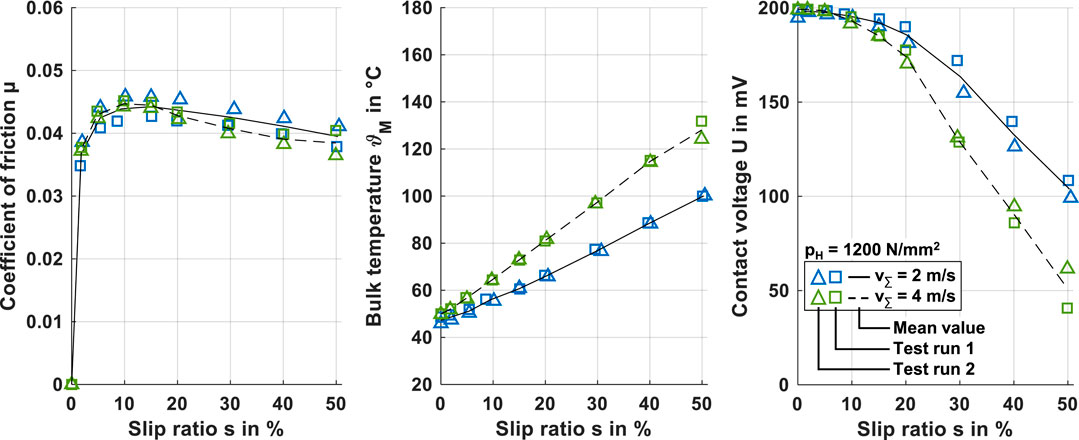
FIGURE 10. Measured coefficients of friction µ, bulk temperatures ϑM and contact voltages U over slip ratio s for pH = 1200 N/mm2 and vΣ = {2, 4} m/s under oil injection lubrication at the twin-disk tribometer.
Figure 11 shows Δµ, ΔϑM and ΔU for pH = 1200 N/mm2 and vΣ = {2, 4} m/s. The relative coefficient of friction Δµ (left) indicates quite similar coefficients of friction in comparison of DoD and injection lubrication. With increasing slip ratio, Δµ decreases. This is related to thermal effects. As the relative bulk temperature ΔϑM (middle) is significantly greater than 1, the bulk and contact temperature are higher and the reduction of friction more pronounced with DoD lubrication, particularly at high slip ratio. The relative contact voltage ΔU (right) shows values around 1 for slip ratio s ≤ 30% and values < 1 for s > 30%. This indicates that the lubrication regime is similar, but for high slip ratio mixed lubrication is slightly more pronounced with DoD lubrication.
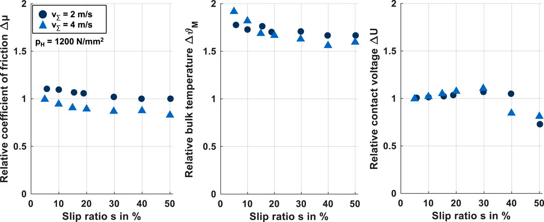
FIGURE 11. Comparison of DoD and injection lubrication at the twin-disk tribometer by relative quantities Δµ, ΔϑM and ΔU over slip ratio s for pH = 1200 N/mm2 and vΣ = {2, 4} m/s.
The comparison between DoD and injection lubrication underlines that for DoD lubrication a typical EHL contact is formed in the disk contact. A main difference between DoD and injection lubrication is the heat balance. As heat dissipation with DoD lubrication is limited, the resulting higher bulk and contact temperature have a greater effect on the tribosystem. In comparison to experiments with one-time MQL by Bobzin et al. (2019), Bobzin et al. (2020a) and Bobzin et al. (2020b), DoD lubrication clearly shows an improvement in the operation stability of the tribosystem. For one-time MQL, a poor repeatability with high scattering in measured friction was found for uncoated surfaces particularly.
Experiments at Gear Test Rig
The investigations at the twin-disk tribometer showed promising results for DoD lubrication of rolling-sliding contacts. On this basis, experiments at the FZG gear efficiency test rig are performed.
Figure 12 shows measured total loss torques TL, tooth bulk temperatures ϑM1 and contact voltages U for no-load and different loads given by the Hertzian pressure at the pitch point pC. In each diagram the results of the first and second test run are shown over the circumferential speed for vt = {0.5, 2.0, 5.0, 8.3} m/s. The DoD lubrication method is used as described in Drop-On-Demand Oil Supply. Each measuring point refers to a mean value over one minute at the end of each operating condition.
For no-load, loss torque TL increases slightly with increasing circumferential speed vt. This is mainly due to an increase in sealing, bearing and gear no-load losses. Churning and squeezing losses are negligible, as almost no oil is splashing around. Tooth bulk temperature ϑM1 stays almost constant at 60°C, as the housing temperature is conditioned at 60°C and no load-dependent losses are present.
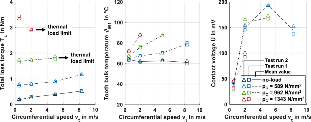
FIGURE 12. Measured total loss torques TV, bulk temperatures ϑM1 and contact voltages U over circumferential speed vt for no-load and different loads under DoD lubrication at the gear test rig.
For loaded conditions, loss torque TL increases compared to no-load conditions. This is due to load-dependent losses of gears and bearings, which increase with increasing load. The difference between the loss torque measured under load and the no-load loss torque can be interpreted as load-dependent loss torque. For all considered operating conditions, the load-dependent losses from the gears are dominant. For pC = 589 N/mm2, the load-dependent loss torque results in an increase in the tooth bulk temperature of the pinion up to ϑM1 = 80°C at vt = 8.3 m/s. Contact voltage U increases with increasing circumferential speed mainly due to an increase in lubricant film thickness in the gear contact. The decrease from vt = 5.0 m/s to 8.3 m/s was not expected. For pC = 962 N/mm2, load-dependent loss torque and tooth bulk temperature further increase. At vt = 8.3 m/s, ϑM1 exceeds 160°C before the testing time of 5 minutes is elapsed. Contact voltage U increases with increasing circumferential speed similar to pC = 589 N/mm2. At vt = 5.0 m/s, U is smaller compared to pC = 589 N/mm2, which can be related to a higher value of ϑM1. For pC = 1343 N/mm2, the load-dependent loss torque is highest. Measured loss torque TL shows a decrease from vt = 0.5 m/s to 2.0 m/s together with a strong increase in tooth bulk temperature. At vt = 5.0 m/s, ϑM1 exceeds 160°C before the testing time of 5 minutes is elapsed. Contact voltage U increases from vt = 0.5 m/s to 2.0 m/s due to increasing circumferential speed, but is smaller at 2.0 m/s compared to pC = 962 N/mm2 indicating more severe mixed lubrication.
For all considered operating conditions, the comparison between the first and second test run shows the good repeatability of the experiments. Inspections of run gear tooth flanks did not evince signs of wear or surface damage. The results show that the stable operation of gears with DoD lubrication is possible. As observed at the twin-disk tribometer, the heat dissipation is limited, resulting in thermal load limits when higher power is transmitted.
The observed operating behavior with gears lubricated by DoD is similar to continuous MQL of gears as shown by Otto (2009) and Höhn et al. (2009). In this study, the mean oil injection volumes are of the same order of magnitude at vt = 8.3 m/s, but can be further reduced for DoD lubrication. The main difference between DoD lubrication and continuous MQL is the oil supply: Continuous MQL uses a continuous air stream as the transporting fluid for very small oil quantities, whereas with DoD lubrication discrete droplets of minimum quantity are directly injected. This allows a flexible response to the need of the gear contact. The droplet supply may be correlated with the gear meshing frequency. The results of contact resistance measurement show that qualitative information on the lubrication regime can be obtained. Such signals can be used to monitor gear contacts and to adjust DoD lubrication on a contact needs-based level.
Conclusion
This study shows that it is generally feasible to operate gears with drop-on-demand lubrication. Friction and temperature measurements in gear-like rolling-sliding contacts indicate the formation of typical elastohydrodynamic contacts. The operational behavior of gears is similar to that in continuous minimum quantity lubrication. Limited heat dissipation can limit the operation regime. Drop-on-demand lubrication introduces the possibility of flexible oil supply on a contact needs-based level to increase energy and resource efficiency of gearboxes. In an optimal way oil is directly used at the gear contact, so that no oil can escape to the environment. The oil supply system can be located directly in the gearbox. Drop-on-demand lubrication can be complemented by sensor systems monitoring the gear contact in order to adjust the droplet supply parameters. As this study shows only the initial feasibility of drop-on-demand lubrication of gears, further work can focus on the influence of gear ventilation on droplet supply, on optimal droplet supply parameters in the context of sensor integration and on measures to reduce load-dependent power losses to shift thermal load limits.
Data Availability Statement
The datasets presented in this article are not readily available because the main data generated or analyzed during this study are included in this published article. Requests to access the datasets should be directed to the corresponding author.
Author Contributions
MM, ET, and MY: methodology; MM and ET: experimental investigation; resources: Gear Research Centre (FZG) - Technical University of Munich (TUM), Engineering Fluid Dynamics Group - University of Twente; data curation: ET and MY; writing - original draft preparation: MM, MY, and TL; writing - review and editing: MM, MY, TL, and CV; supervision: TL and CV. All authors have read and agreed to the published version of the manuscript.
Conflict of Interest
The authors declare that the research was conducted in the absence of any commercial or financial relationships that could be construed as a potential conflict of interest.
Publisher’s Note
All claims expressed in this article are solely those of the authors and do not necessarily represent those of their affiliated organizations, or those of the publisher, the editors and the reviewers. Any product that may be evaluated in this article, or claim that may be made by its manufacturer, is not guaranteed or endorsed by the publisher.
References
Albahrani, S., Philippon, D., Vergne, P., and Bluet, J. (2016). A Review of In Situ Methodologies for Studying Elastohydrodynamic Lubrication. Proc. Inst. Mech. Eng. J: J. Eng. Tribology 230, 86–110. doi:10.1177/1350650115590428
Andersson, M., Sosa, M., and Olofsson, U. (2017). Efficiency and Temperature of Spur Gears Using Spray Lubrication Compared to Dip Lubrication. Proc. Inst. Mech. Eng. Part J: J. Eng. Tribology 231 (11), 1390–1396. doi:10.1177/1350650117695709
Björling, M., Larsson, R., and Marklund, P. (2014). The Effect of DLC Coating Thickness on Elstohydrodynamic Friction. Tribol Lett. 55, 353–362. doi:10.1007/s11249-014-0364-6
Bobzin, K., Brögelmann, T., and Kalscheuer, C. (2020). Arc PVD (Cr,Al,Mo)N and (Cr,Al,Cu)N Coatings for Mobility Applications. Surf. Coat. Technology 384 (125046), 1–12. doi:10.1016/j.surfcoat.2019.125046
Bobzin, K., Brögelmann, T., Kalscheuer, C., Stahl, K., Lohner, T., and Yilmaz, M. (2019). (Cr,Al)N and (Cr,Al,Mo)N Hard Coatings for Tribological Applications under Minimum Quantity Lubrication. Tribology Int. 140 (105817), 1–10. doi:10.1016/j.triboint.2019.06.010
Bobzin, K., Brögelmann, T., Kalscheuer, C., Stahl, K., Lohner, T., and Yilmaz, M. (2020). Effects of (Cr,Al)N and (Cr,Al,Mo)N Coatings on Friction under Minimum Quantity Lubrication. Surf. Coat. Technology 402 (126154), 1–10. doi:10.1016/j.surfcoat.2020.126154
Bobzin, K., Brögelmann, T., Stahl, K., Michaelis, K., Mayer, J., and Hinterstoißer, M. (2015). Friction Reduction of Highly-Loaded Rolling-Sliding Contacts by Surface Modifications under Elasto-Hydrodynamic Lubrication. Wear 328-329, 217–228. doi:10.1016/j.wear.2015.02.033
Chen, A. U., and Basaran, O. A. (2002). A New Method for Significantly Reducing Drop Radius without Reducing Nozzle Radius in Drop-On-Demand Drop Production. Phys. Fluids 14 (1), L1–L4. doi:10.1063/1.1427441
Chevalier, F., Lubrecht, A. A., Cann, P. M. E., Colin, F., and Dalmaz, G. (1998). Film Thickness in Starved EHL Point Contacts. J. Tribology 120, 126–133. doi:10.1115/1.2834175
Chin, Z. Y., Smith, W. A., Borghesani, P., Randall, R. B., and Peng, Z. (2021). Absolute Transmission Error: A Simple New Tool for Assessing Gear Wear. Mech. Syst. Signal Process. 146, 107070. doi:10.1016/j.ymssp.2020.107070
Clarke, A., Weeks, I. J. J., Evans, H. P., and Snidle, R. W. (2016). An Investigation into Mixed Lubrication Conditions Using Electrical Contact Resistance Techniques. Tribology Int. 93, 709–716. doi:10.1016/j.triboint.2014.10.010
Damiens, B., Venner, C. H., Cann, P. M. E., and Lubrecht, A. A. (2004). Starved Lubrication of Elliptical EHD Contacts. ASME J. Lubrication Technology 126 (1), 105–111. doi:10.1115/1.1631020
De Barros Bouchet, M.-I., Matta, C., Le-Mogne, T., Martin, J. M., Zhang, Q., Ill, G. W., et al. (2007). Superlubricity Mechanism of Diamond-like Carbon with Glycerol. Coupling of Experimental and Simulation Studies. J. Phys. Conf. Ser. 89, 1–14. doi:10.1088/1742-6596/89/1/012003
De Barros Bouchet, M. I., Martin, J. M., Avila, J., Kano, M., Yoshida, K., Tsuruda, T., et al. (2017). Diamond-like Carbon Coating under Oleic Acid Lubrication: Evidence for Graphene Oxide Formation in Superlow Friction. Sci. Rep. 7, 1–13. 46394. doi:10.1038/srep46394
Derby, B. (2010). Inkjet Printing of Functional and Structural Materials: Fluid Property Requirements, Feature Stability, and Resolution. Annu. Rev. Mater. Res. 40, 395–414. doi:10.1146/annurev-matsci-070909-104502
Doleschel, A., Michaelis, K., and Höhn, B.-R. (2002). FVA-No. 345 Information Sheet - Method to Determine the Frictional Behaviour of Lubricants Using a FZG Gear Test Rig. Frankfurt/Main: Forschungsvereinigung Antriebstechnik e.V.
Doleschel, A. (2003). Wirkungsgradberechnung von Zahnradgetrieben in Abhängigkeit vom Schmierstoff [Efficiency Calculation of Gearboxes depending on the Lubricant]. Dissertation Technical University of Munich, Munich, Germany.
Duineveld, P., de Kok, M., Buechel, M., Sempel, A., Mutsaers, K., van de Weijer, P., et al. (2002). Ink-jet Printing of Polymer Light-Emitting Devices. Proc. SPIE, 4464. doi:10.1117/12.457460
Ebner, M., Lohner, T., Michaelis, K., Höhn, B.-R., and Stahl, K. (2017). Self-Lubricating Gears with Oil-Impregnated Sintered Materials. Forsch Ingenieurwes 81, 175–190. doi:10.1007/s10010-017-0227-z
Ebner, M., Omasta, M., Lohner, T., Šperka, P., Krupka, I., Hartl, M., et al. (2018). Local Effects in EHL Contacts with Oil-Impregnated Sintered Materials. Lubricants 7 (1). doi:10.3390/lubricants7010001
Ebner, M., Yilmaz, M., Lohner, T., Michaelis, K., Höhn, B.-R., and Stahl, K. (2018). On the Effect of Starved Lubrication on Elastohydrodynamic (EHL) Line Contacts. Tribology Int. 118, 515–523. doi:10.1016/j.triboint.2017.06.004
Fromberger, M., Sendlbeck, S., Rothemund, M., Götz, J., Otto, M., and Stahl, K. (2019). Comparing Data Sources for Condition Monitoring Suitability. Forsch Ingenieurwes 83, 521–527. doi:10.1007/s10010-019-00331-y
Furey, M. J., and Appeldoorn, J. K. (1962). The Effect of Lubricant Viscosity on Metallic Contact and Friction in a Sliding System. A. S L. E Trans. 5 (1), 149–159. doi:10.1080/05698196208972462
Glovnea, R., Furtuna, M., Nagata, Y., and Sugimura, J. (2012). Electrical Methods for the Evaluation of Lubrication in Elastohydrodynamic Contacts. Tribology Online 7, 46–53. doi:10.2474/trol.7.46
Hinterstoißer, M., Sedlmair, M., Lohner, T., and Stahl, K. (2019). Minimizing Load-dependent Gear Losses. Tribologie und Schmierungstechnik: 66 (3), 15–25.
Hinterstoißer, M. (2014). Zur Optimierung des Wirkungsgrades von Stirnradgetrieben [On the Optimization of the Efficiency of Spur Gearboxes]. Dissertation Technical University of Munich, Munich Germany.
Höhn, B.-R., Michaelis, K., and Otto, H.-P. (2009). Minimised Gear Lubrication by a Minimum Oil/air Flow Rate. Wear 266, 461–467. doi:10.1016/j.wear.2008.04.037
Kleemola, J., and Lehtovaara, A. (2010). Evaluation of Lubrication Conditions in Gear Contacts Using Contact Resistance and Bulk Temperature Measurements. Proc. Inst. Mech. Eng. Part J: J. Eng. Tribology 224 (4), 367–375. doi:10.1243/13506501jet675
Kuwahara, T., Romero, P. A., Makowski, S., Weihnacht, V., Moras, G., and Moseler, M. (2019). Mechano-Chemical Decomposition of Organic Friction Modifiers with Multiple Reactive Centres Induces Superlubricity of Ta-C. Nat. Commun. 10, 151–211. doi:10.1038/s41467-018-08042-8
Liu, D.-L., Cao, S.-H., Zhang, S.-F., and Xu, J.-J. (2016). Lubrication Film Thickness Calculation from Contact Resistance Measurement in Point Contact. Ind. Lubrication Tribology 68, 176–182. doi:10.1108/ilt-04-2015-0057
Lohner, T. (2016). Berechnung von TEHD Kontakten und Einlaufverhalten von Verzahnungen [Calculation of TEHL Contacts and Running-in Behaviour of Gears]. Dissertation Technical University of Munich, Munich Germany.
Lugt, P. M., Severt, R. W. M., Fogelströ, J., and Tripp, J. H. (2001). Influence of Surface Topography on Friction, Film Breakdown and Running-In in the Mixed Lubrication Regime. Proc. Inst. Mech. Eng. Part J: J. Eng. Tribology 215, 519–533. doi:10.1243/1350650011543772
Mayer, J. (2013). Einfluss der Oberfläche und des Schmierstoffs auf das Reibungsverhalten im EHD-Kontakt [Influence of Surface Texture and Lubricant on the Frictional Behaviour of EHL Contacts]. Dissertation Technical University of Munich, Munich Germany.
McKinley, G. H., Renardy, M., and von Ohnesorge, Wolfgang. (2011). Wolfgang von Ohnesorge. Phys. Fluids 23 (12), 127101. doi:10.1063/1.3663616
Moss, J., Kahraman, A., and Wink, C. (2018). An Experimental Study of Influence of Lubrication Methods on Efficiency and Contact Fatigue Life of Spur Gears. J. Tribology 140, 1–11. doi:10.1115/1.4039929
Omasta, M., Ebner, M., Šperka, P., Lohner, T., Krupka, I., Hartl, M., et al. (2018). Film Formation in EHL Contacts with Oil-Impregnated Sintered Materials. Ilt 70 (4), 612–619. doi:10.1108/ilt-11-2017-0340
Otto, H.-P. (2009). Flank Load Carrying Capacity and Power Loss Reduction by Minimised Lubrication. Dissertation Technical University of Munich.
Pemberton, J., and Cameron, A. (1976). A Mechanism of Fluid Replenishment in Elastohydrodynamic Contacts. Wear 37, 185–190. doi:10.1016/0043-1648(76)90190-3
Reis, N., and Derby, B. (2000). Ink Jet Deposition of Ceramic Suspensions: Modeling and Experiments of Droplet Formation. MRS Proc. 625, 117–122. doi:10.1557/proc-625-117
Reynolds, O. (1886). IV. On the Theory of Lubrication and its Application to Mr. Beauchamp tower's Experiments, Including an Experimental Determination of the Viscosity of Olive Oil, Phil. Trans. R. Soc., In Experimental Determination of the Viscosity of Olive Oil. Philosophical Transactions, 177. The Royal Society Publishing, London United Kingdom, 157–234. doi:10.1098/rstl.1886.0005
Schwarz, A., Ebner, M., Lohner, T., Stahl, K., Bobzin, K., Brögelmann, T., et al. (2020). DLC-coated Spur Gears – Part I: Friction Reduction. Ind. Lubrication Tribology 73 (3), 457–469.
Shell Chemicals (2017). Cargo Handling Sheet, Sheel HVI 60. [Webpage]. Retrievef from https://www.shell.com
SKF, (2014). SKF Hauptkatalog 2014 [SKF Main Catalogue 2014]. Media-Print Informationstechnologie, Chennai India.
Touret, T., Changenet, C., Ville, F., Lalmi, M., and Becquerelle, S. (2018). On the Use of Temperature for Online Condition Monitoring of Geared Systems - A Review. Mech. Syst. Signal Process. 101, 197–210. doi:10.1016/j.ymssp.2017.07.044
Van der Kruk, W. M., Smit, S. A., Segers, T. J., Li, X. M., and Venner, C. H. (2019). Drop-on-Demand Printing as Novel Method of Oil Supply in Elastohydrodynamic Lubrication. Tribology Lett. 67 (3), 1–12. doi:10.1007/s11249-019-1208-1
Van Zoelen, M. T., Venner, C. H., and Lugt, P. M. (2009). Prediction of Film Thickness Decay in Starved Elasto-Hydrodynamically Lubricated Contacts Using a Thin Layer Flow Model. Proc. Inst. Mech. Eng. Part J: J. Eng. Tribology 223, 541–552. doi:10.1243/13506501jet524
Van Zoelen, M. T., Venner, C. H., and Lugt, P. M. (2010). The Prediction of Contact Pressure-Induced Film Thickness Decay in Starved Lubricated Rolling Bearings. Tribology Trans. 53, 831–841. doi:10.1080/10402004.2010.492925
Venner, C. H., Popovici, G., Lugt, P. M., and Organisciak, M. (2008). Film Thickness Modulations in Starved Elastohydrodynamically Lubricated Contacts Induced by Time-Varying Lubricant Supply. ASME J. Lubrication Technology 130, 041501-01–041501-10. doi:10.1115/1.2958069
Venner, C. H., Berger, G., and Lugt, P. M. (2003). Waviness Deformation in Starved EHL Circular Contacts. ASME J. Lubrication Technology 126, 248–257. doi:10.1115/1.1572514
Wedeven, L. D., Evans, D., and Cameron, A. (1971). Optical Analysis of Ball Bearing Starvation. ASME J. Lubrication Technology 93, 349–361. doi:10.1115/1.3451591
Wijnant, Y. H., and Venner, C. H. (1999). Contact Dynamics in Starved Elastohydrodynamic Lubrication, 36. Elsevier Tribology Ser., 705–716. doi:10.1016/s0167-8922(99)80089-3
Wimmer, A. J. (2006). Lastverluste von Stirnradverzahnungen - Konstruktive Einflüsse, Wirkungsgradmaximierung, Tribologie [Load-dependent Losses of Spur Gears – Design Influences, Efficiency Maximization, Tribology]. Dissertation Technical University of Munich, Munich Germany.
Yeong, Y. H., Mudafort, R., Steele, A., Bayer, I., and Loth, E. (2012). Water Droplet Impact Dynamics at Icing Conditions with and without Superhydrophobicity, In. 4th AIAA Atmospheric and Space Environments Conference. doi:10.2514/6.2012-3134
Yilmaz, M., Lohner, T., Michaelis, K., and Stahl, K. (2019). Minimizing Gear Friction with Water-Containing Gear Fluids. Forsch Ingenieurwes 83, 327–337. doi:10.1007/s10010-019-00373-2
Yilmaz, M., Lohner, T., and Stahl, K. (2020). Bearing Power Losses with Water-Containing Gear Fluids. Lubricants 8 (1). 5. doi:10.3390/lubricants8010005
Yilmaz, M., Mirza, M., Lohner, T., and Stahl, K. (2019). Superlubricity in EHL Contacts with Water-Containing Gear Fluid. Lubricants 7 (5), 46. doi:10.3390/lubricants7050046
GLOSSARY
A Begin of contact
b Face width mm
C Pitch point
Ca Tip relief µm
E End of contact
fDoD Droplet frequency 1/s
fN Line load N/mm
fz Tooth meshing frequency 1/s
FN Normal force N
FR Friction force N
mn Normal module mm
Oh Ohnesorge number
pet Transverse pitch mm
P Power W
R Resistance Ω
Ra Arithmetic mean roughness µm
Re Reynolds number
s Slip ratio %
T Torque Nm
U Voltage V
vg Sliding velocity m/s
vt Circumferential speed m/s
v∑ Sum velocity m/s
We Weber number
z Number of teeth -
Greek symbols
αn Normal pressure angle °
β Helix angle °
εγ Total contact ratio
ρ Oil density kg/m3
Indices
0 No-load
1 Pinion
2 Wheel
B Bearing
C Pitch point
DoD Drop-on-Demand
G Gear
inj Injection
In Input
L Loss
P Load-dependent
S Sealing
Keywords: gears, drop-on-demand, lubrication, contact resistance, friction, power loss, temperature, heat balance
Citation: Mirza M, Yilmaz M, Thieme E, Lohner T and Venner CH (2021) Drop-On-Demand Lubrication of Gears: A Feasibility Study. Front. Mech. Eng 7:746407. doi: 10.3389/fmech.2021.746407
Received: 23 July 2021; Accepted: 07 September 2021;
Published: 01 October 2021.
Edited by:
Alessandro Ruggiero, University of Salerno, ItalyReviewed by:
Carsten Gachot, Vienna University of Technology, AustriaMarcus Björling, Luleå University of Technology, Sweden
Copyright © 2021 Mirza, Yilmaz, Thieme, Lohner and Venner. This is an open-access article distributed under the terms of the Creative Commons Attribution License (CC BY). The use, distribution or reproduction in other forums is permitted, provided the original author(s) and the copyright owner(s) are credited and that the original publication in this journal is cited, in accordance with accepted academic practice. No use, distribution or reproduction is permitted which does not comply with these terms.
*Correspondence: T. Lohner, lohner@fzg.mw.tum.de