The integration of morphological design and topology optimization to enhance the visual quality of electricity pylons
 Luca Di Angelo
 Rocco Furferi
 Francesco Gherardini
 Emanuele Guardiani1
- 1Department of Industrial and Information Engineering and Economics, University of L’Aquila, L'Aquila, Italy
- 2Department of Industrial Engineering, University of Florence, Florence, Italy
- 3Department of Engineering “Enzo Ferrari”, University of Modena and Reggio Emilia, Modena, Italy
Purpose: This paper aims to enhance the visual quality of artificial above-ground structures, like pylons, masts, and towers of infrastructures and facilities, through a systematic design method for their morphological and structural optimization.
Design/methodology/approach: The method achieves the functional and aesthetic goals based on the application of computer-aided tools. In particular, this is achieved according to three key steps:
• Morphological development of landscape-related symbolism, environment, or culture and social needs.
• Topology optimization of the design concept to reduce the structural weight and its visual impact.
• Engineering of the resulting optimized structure.
Practical implications: As a case study, the method is used for designing electricity pylons for the coastal territory of a Mediterranean European country, such as Italy. Citizens were involved during the identification phase of a symbolic shape for the concept development and during the final assessment phase.
Research limitations/implications: The engineering phase has been performed by assembling standard lattice components with welded connections. Even if the use of this truss-like structure should lead to a minimum cost, the developed structure employs an additional 15%–20% of trusses and sheet metal covers the final cost is higher than a standard lattice pylon.
Findings: The result is a structure with enhanced visual quality according to the international guidelines and fully complying with mandatory and functional requirements, such as regulatory and industrial feasibility, as well as those arising from social components.
Originality/value: The method shows its potential in defining a custom design for lightweight structures with enhanced visual quality regarding the critical situation discussed here. The method considers both the subjective perception of citizens and their priorities and the landscape where the structures will be installed.
1 Introduction
High-voltage power lines, wind turbines, telecommunication antennas, viaducts, and road/railways bridges are artificial above-ground artifacts that, on the one hand, enhance human activity but, on the other hand, appear as huge structures that impact the natural landscape. This generates a controversial situation in public opinion, which sees opposing factions between facilities, beneficiaries, and detractors for their impact (e.g., citizens living in the installation areas). Besides possible health considerations, which lie outside our research, the main reason for citizen opposition is the impact of these structures that, disturbing the aesthetics and visual perception of natural and rural landscapes, may have negative effects on society, tourism, ecology, and so on.
Among the several structures, one of them has the most significant visual impact (VI) element: the pylon, also called mast or tower, which is a vertical and, usually, lattice structure. Many studies published in the related literature [Shea and Smith, 2006; Byrne et al. (2015); Guo and Li, 2011; Chen et al. (2014); De Souza et al. (2016)] are focused on the Topology Optimization (TO) of these reticular structures, to reduce the amount of the material. Among the others, we underline the following works: Cicconi et al. (2020) developed a method to design and size a system of supports for electric lines that interacts with each other under specific load conditions using an approach based on the theory of the Constraint Satisfaction Problem. The object-oriented model of a transmission line has been described when the designer defines the variables to be optimized as geometrical dimensions, pole locations, cable pre-tension, etc., under a set of constraints. Hofer et al. (2022) face the cableway pylon design problem through a TO framework developed explicitly for large-scale engineering examples. The result is a lattice-truss-like topology developed into a high-performance, efficient and economical lightweight structure.
All these approaches consider the structures’ cost, transportation, erection, and maintenance but neglect their visual quality enhancement.
To cope with this issue, some studies and guidelines provided by national institutions [e.g., United States Department of the Interior, 2013; Reed (2011); Environmental Protection Department (2013)] have been published in the literature. Reed (2011) defined the visual impact as any alteration to landscape natural features, such as landforms, waterways, or plants, as well as the addition of buildings or other man-made elements that alter the visual character or quality of a landscape due to visual contrasts in the basic elements of form, line, color and texture. Furthermore, Reed (2011) establishes a set of guidelines about siting and design, construction operations, decommissioning, and reclamation of infrastructures. In particular, the section “Design” provides the following advices:
• The custom-designed structures should be used to reduce the visual impact and better integrate with the landscape;
• Different types of structures, such as monopole, guyed, and lattice structures/towers, should be appropriately chosen to better accord with the landscape;
• All characteristic features of the structure, such as materials and surface treatments, should be selected to mimic the surrounding landscape’s form, line, color, and appearance.
The Environmental Protection Department (2013)addresses the visual impact concerning two distinct parts, a baseline survey and a visual impact assessment, which includes the identification of:
• The sources of visual impact, and their magnitude, that would be generated during the construction and operation phases of the proposed works;
• The principal visual impacts considering the degree of change to the baseline conditions.
However, the results of the designer’s application of these guidelines for evaluating the potential visual impact still depend on her/his subjectivity.
Moreover, according to Koglin and Gross (1988), two trend lines are to be taken into account:
• The improvement of the visual impact of pylons and similar vertical structures is particularly critical, since they are viewed from a great distance;
• The visual impact depends on the landscape, position of the pylon, viewpoint of the observer and the contrast between the structure and its surroundings.
Due to the subjectivity of the visual impact perception, different approaches have been published in the related literature to aid the designer in mitigating new structures.
Turnbull and Gourlay (1987) proposed for the first time a computer-based method for visual impact analysis: the proposed software application was able to evaluate alternative structures (e.g., transmission line pylons) based on data collection, visibility, and visualization requirements. This application suffers strongly from limitations because of the computer graphics available in the eighties; to the authors’ knowledge, there have been no updates.
Sumper et al. (2010), proposed a measure of the visual impact of different pylons in the same situation
where:
V: the visibility of the infrastructure.
F: the fragility of the landscape, that is, its capability to increase or decrease the impact.
IQ: the quality of the analyzed area (rural, commercial, industrial, etc.).
The numerical values for the three aforementioned parameters are assessed according to subjectively estimated impacts (i.e., none = 1; low = 3; middle = 9; high = 27). This expression only considers the abovementioned recommendations of Reed (2011) marginally.
Even in the most recent years, the Visual Impact Assessment (VIA) of artificial structures is analyzed and studied by a very small percentage of peer-reviewed journal articles (Palmer, 2022a). This fact opens the need for new approaches, mainly quantitative ones. Palmer (2022b), stating that the wind project VIA is dominated by photography-based simulations at a limited number of viewpoints, provided an approach to assessing the visual prominence of individual wind turbines based on their distance from the viewer and the visual exposure of such turbines.
In Priestley and Evans (1996) and Atkinson et al. (2006), the results of a direct comparison between new pylon designs and their conventional lattice structure are proposed. These studies state that, in most cases, people prefer alternative pylon designs to conventional ones. Even if the real motivations are uncertain, citizens have a negative perception dictated by the traditional lattice design, as if the impact of the infrastructure is directly associated with their reticular structure.
Since the visual impact remains a subjective perception, with no objective coding available, according to Cotton and Devine-Wright (2013), citizens must be involved in designing new installations through consultation, design contests, and participatory workshops. In the last case, deliberative focus group techniques are employed to investigate the perceptions of environmental and social impacts, risks, governance arrangements, and technology choices, as in Cotton and Devine-Wright (2013).
On the other hand, design competitions exploit the psychological perception of direct participation in the design process and target identifying new ideas through crowdsourcing. Nevertheless, the results of these initiatives are limited by citizens’ lack of technical knowledge necessary for the strategic development of facilities, as in Cotton and Devine-Wright (2013). Consequently, the proposed solutions generally stop at the conceptual stage, as in Dapogny et al. (2017), because of limitations due to non-compliance with regulations, safety, or non-feasibility.
Regarding high voltage power lines (HVPL), which primarily include pylons, but also conductors, protective ropes, hood, and pin insulators, the previously described approaches have been applied with positive results in the following examples:
• The “T-pylon” [see Frearson, 2015], which was installed in the United Kingdom in 2015 (Figure 1A);
• The “Germoglio pylon”, which was installed in Italy in 2014 (Figure 1B);
• The “Foster pylon” [see Foster and Partners, (2010)], which was installed in Italy in 2009 (Figure 1C).
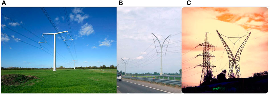
FIGURE 1. (A) T-pylon (Photo credits: Jonathan Thacker, “Grassland and T pylons”, licensed under the Creative Commons Attribution-ShareAlike 2.0 Generic (CC BY-SA 2.0), Available online: https://www.geograph.org.uk/photo/7309807); (B) Germoglio pylon (Photo credits: Andreas Karrer, “Freileitungsmast-Italien”, licensed under the Creative Commons Attribution-Share Alike 4.0 International license. Available online: https://commons.wikimedia.org/wiki/File:Freileitungsmast-Italien.jpg); (C) Foster pylon (Photo credits: Giagir, “Lui e Lei Elettrici”, for kind permission of Giagir, Available online: https://www.flickr.com/photos/giagir/4506245610/in/photolist-7QegTf-7ScFPQ).
To investigate the social and psychological factors that might explain preferences for alternative pylon designs, in Devine-Wright and Batel (2013), the “T-pylon” is compared with two other different designs: the “A frame”, namely the conventional pylon, and the “Totem”, whose design is not so far from the conventional one). The comparison is performed by considering the preferences of 1519 UK citizens for alternative designs. The results of the survey are multiple and interesting:
• Generally, the visual impact of pylons with a traditional design is probably perceived as negative due to the historical associations with being enormous, monstrous, ugly, and eyesores.
• Changing pylon designs is one of the least supported measures for enhancing the visual quality of HVPL.
• Involving residents in the early design process as decision-makers can represent a measure that could improve the levels of acceptability of new structures.
• It is important to have “a more local and contextual approach for decision-making that considers the characteristics, concerns, needs, and expectations of the specific communities to be affected”.
By analyzing all the new pylons mentioned in Figure 1, it is evident that, concerning the traditional ones, they aim at reducing the visual impact by attractive and sinuous shapes, but without completely adopting the guidelines in Reed (2011) and the conclusions in Devine-Wright and Batel (2013). The most important aspect overlooked is the transposition into the structure shape of the characteristic elements easily identifiable with the surroundings where they are installed; certainly, this would allow them to be better integrated with the landscape, further improving their impact.
To improve the visual quality of the above-ground structures, a systematic method for their design is presented here, considering the typical requirements (e.g., regulatory and industrial feasibility) and those coming from social components. We applied the method to designing electrical pylons for the coastal territory of a Mediterranean European country, such as Italy. It resulted in a new shape that, compared by residents with the state-of-the-art, has been identified as the one that best suits the coastal territory.
2 An integrated design method for visual quality enhancement
The current state-of-the-art pylon (mast or tower) design comprises optimized and effective structures based on trusses realized in galvanized steel. These vertical structures have the same shape in areas with high landscape interest, regardless of where they are placed. As shown by research published in the literature and analyzed in the previous section, see, for example, Devine-Wright and Batel (2013), these structures, even if reticular, are considered to have a visual impact.
Based on these considerations, it is fundamental to propose a method for designing pylons that can define a shape with enhanced visual quality. According to this purpose, the design process may benefit from integrating two key aspects:
• The definition of structures starting from a shape that can be symbolically representative of the landscape, the environment, or the cultural context of the installation site; all this without neglecting the more traditional requirements of the suspension of electricity transmission and distribution lines, such as those relating to regulatory aspects related to security. The goal is to transform the pylon from an impacting structure into a structure representative of the context where it is installed. The starting shape model may be achieved through direct CAD modeling, reverse modeling, or their integration (see Company et al. (2020); Urick et al. (2018); Buonamici et al. (2018); Nyirenda and Bronsvoort, 2008; Goldbach et al., 2020).
• The reduction of volume and, therefore, material and weight by integrating TO in the design workflow to enhance the structure’s visual impact without affecting its function, already early in the design phase (see Bici et al. (2017); López et al., 2017; Müller et al. (1999); Dalpadulo et al. (2020); Mo et al. (2022); Gythiel et al. (2020); Brütting et al., 2020). More recent works focus on TO combined with additional techniques, but without considering aesthetics: Wang et al. (2021) showed that the approach of structural generation based on TO and deep learning is feasible, generating innovative structures and optimizing material consumption and mechanical performance.
The introduction of structural optimization in the design process may support the designers’ creativity, improving the design quality, as in Müller et al. (1999). Some recent studies explore structural form-finding methods to explore morphological and structural conceptual variants. He et al. (2022) moved a step forward to aesthetics, by proposing a methodology to produce multiple high-performance designs with distinct topologies, with practical applications in architecture and engineering, where the structural complexity usually needs to be controlled to balance the aesthetic, functional, economical, and other considerations. A similar approach is proposed by Lin et al. (2021), by integrating TO and parametric design theory, combined with multi criteria decision-making analysis. They efficiently obtain several architectural morphologies with both structural rationality and aesthetic rules, which lead to the exploration of design alternatives. Yu et al. (2022) proposed a structural form-finding method based on principal stress lines by using parametric tools to extrapolate component forms during the conceptual stage. The method allows architects to create structural texture with formal aesthetics and modify it in real time on the basis of structural analysis results. Again, Xiaoyu et al. (2021) proposed the conceptual and aesthetical design of the pylons of cable-stayed bridges using a new form finding method, considering aesthetic rules and morphologic feature from local culture to achieve harmony between the bridge and the environment. This last work is consistent with the goal of our work but is limited to the early design phase. Furthermore, Li Y. et al. (2022) proposed a framework to generate rapid design and performance evaluation of triangular/quadrilateral grids for free-form structure design that, compared with TO, can better meet the requirements of architectural aesthetics and industrial production. However, the resulting grids consisted of conceptual designs without further developments.
The complete design of new pylons in long-spam bridges is proposed–from conceptual to detailed design - considering functionality, ease of construction, and aesthetic properties in Li Z. et al. (2022). This work proposed the whole process to obtain the detailed design of a new long-span bridge type from the form-finding to multi-material TO. However, it did not consider the integration of the visual quality of the structures with the landscape, nor involved citizens in the development process.
To move in this direction, the proposed method follows the well-known four stages of the design method provided by Kim et al. (2002), whose flowchart is in Figure 2. In such a method, the identification of technical specifications takes into account the enhancement of visual quality.
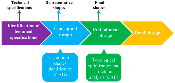
FIGURE 2. Flow-chart of the proposed method.
Specifically, the proposed approach consists of the following four steps:
1) The first step follows a systematic approach that, starting from the identification of requirements, defines a set of technical specifications (Figure 3):
• Standard and legislative context.
• Issues concerning the environmental impact.
• Identification and analysis of the needs of potential customers.
• Functional analysis.
2) The conceptual solutions for a new pylon using symbolic references to the landscape, environment, or culture and social needs are developed as follows (see Figure 4):
• Identifying a representative shape.
• Developing a 3D CAD model of the pylon that is shaped in accordance with the prior step.
• Selecting the concept.
3) Each concept (i.e., each selected shape) is topologically optimized to reduce the structural weight and its visual impact. Then, the structure is engineered in a feasible layout and embodiment by obtaining an industrial product while keeping the original form’s characteristic features.
4) In the last phase, the product design is completed, and the structure is detailed in components, generally standardized and commercial, to develop an economical and straightforward product.
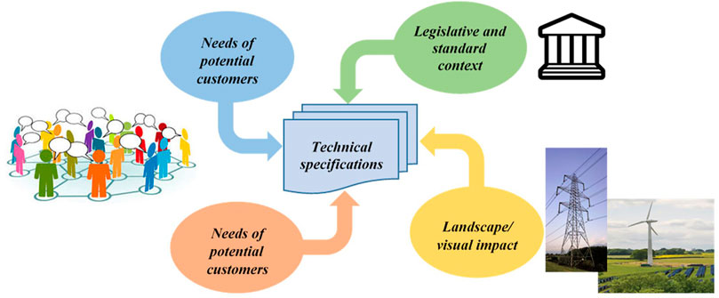
FIGURE 3. Definition of technical specifications.
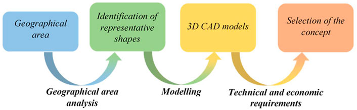
FIGURE 4. Main steps of the development of conceptual solutions.
Where more than one conceptual solution is proposed, the most promising one is selected by considering the following requirements:
• Technical-functional suitability, that is, consistency with the technical specification and current legislation.
• Flexibility of use, that is, the possibility of using the pylon in similar contexts and situations, such as areas with high landscape interest or strong anthropization.
• Cost-effectiveness, that is, the choice of material, technological process, and assembly must follow a logic of industrial feasibility.
• Economical operation and maintenance.
A score for each of the above requirements will be assigned to each conceptual solution to compare the solutions.
Through these steps, the proposed methodology for new pylons design advantageously tries to implement the abovementioned recommendations to enhance their inevitable visual impact on the landscape while maintaining the traditional requirements.
3 Case study: Electricity pylon for a 380-kv line for the coastal territory of Italy
The proposed method has general validity and can be applied to all those landscapes where it is possible to identify one or more characteristic shapes. To better explain its different phases and show the obtainable results, the proposed method has been applied for designing a new electricity pylon for a 380-kV line to be installed in the coastal territory of Italy. The choice of this case study guarantees the application of the method in a context where the visual impact of such structures is relevant.
3.1 Identification of technical specifications
The first step aims to identify the technical specifications by considering the relevant legislation and the requirements of visual impact mitigation and analysis of customers’ needs.
The pylon design must comply with the standards and rules established by the International Electro-Technical Commission (IEC). Furthermore, related national and international standards and legislation must be considered depending on the country where the pylons will be installed.
The analysis of the state-of-the-art highlights the common trend in the design of electric pylons is the achievement of a very high level of structural efficiency. Recently, new structures have been developed to consider the aesthetical morphology of attractive and sinuous shapes, but without completely adopting the guidelines in Reed (2011) and the conclusions in Devine-Wright and Batel (2013). For this purpose, the new structures should be designed by identifying specific requirements regarding the impact, depending on whether the facility is to be integrated into high-interest landscape regions, protected areas, or urban contexts.
In the identification and analysis of the needs of potential customers, we can distinguish between a technical customer and a non-technical one, based on how the customer perceives and exposes his or her needs. In the first case, the customer is aware of his/her needs and can directly provide an explicit technical specification; in the second case, the customer has less awareness of his or her needs and cannot communicate them objectively. In the context of electricity power supply, the first type of customer may be represented by an electricity transmission grid operator. In contrast, the second type of customer mainly consists of the entire population. In defining the technical specifications, we consider both customer types to develop strategic lines that respond to the needs of a whole society. Regarding customers’ needs, Pahl and Beitz (1996) distinguish between:
• Simple needs that are satisfied when the product does something inherent in its function.
• Emotional needs that, in some way, are not essential to the goal of the product.
In the design of electricity pylons, the first type is related to the legislative and standard context. In contrast, the second type is associated with the impact and integration with the geographical area of installation.
The proposed case study deals with a third-class line referred to as HHT, with a nominal voltage higher than 30,000 V, concerning the standard context and the Italian Ministerial Decree 21/03/1988 n.449. Figure 5 presents the corresponding requirements. Relating to the environmental impact, the essential requirements deal with the pylon’s impact and its integration with the geographical area of installation. The corresponding requirements are bounded with a solid red line.

FIGURE 5. Technical specifications for a pylon of a 380-kV electricity line.
Once the needs have been identified, they are analyzed and translated into technical language and, consequently, a number of technical specifications are identified. In some cases, this requires the clarification of real needs to correct any misunderstanding. To this end, the decomposition of the need into its detailed sub-needs is carried out. In defining the requirements, some explicit needs coming from potential customers are collected and analyzed: most of them are strictly connected with the visual impact on the landscape.
The functional analysis defines the product functions. Once the functions and sub-functions have been defined, the functional requirements are defined by identifying the quantity (e.g., a numerical target value) associated with the related functions. Then, each requirement is assessed by the designer or citizen by assigning a priority score according to a five-point Likert-type scale, from 1 (no priority) to 5 (high priority).
Finally, to describe the performance of the pylon, all the requirements are translated and integrated into functions; each of them will be given a score assessed by the corresponding technical requirements.
3.2 Development of conceptual solutions for the pylon
The presented methodology for designing a new pylon consists of enhancing the visual quality impact, constrained by the standard and legislative requirements, which are linked to structural and safety aspects. Therefore, the proposed formulation consists of implementing, starting from an early stage of the project, the most important advice obtained by analyzing the related state-of-the-art reported in the “Introduction”.
Di Angelo et al. (2020) reported that different criteria could be defined for each geographical area to identify representative shapes. Based on these results and according to the guidelines proposed by Reed (2011), the geographical elements, the natural elements (e.g., the vegetation), and the items of interest (e.g., the symbolic shapes for the location) are the most relevant. To identify the specific shape that characterizes the Italian coastal territory area, the geography criterion is considered, and the following three symbols are analyzed:
• The anchor.
• The palm tree.
• The sail.
The choice of all symbols identifying the coastal areas has been limited to those whose shapes are adequately streamlined. According to the results reported in Devine-Wright and Batel (2013), residents are involved in participatory design activities (Di Angelo et al. (2020); Gherardini et al. (2017); Hardie (1988); Kempenaar and van den Brink (2018); Luck (2018)) to obtain the shapes that best meet the citizens’ requirements. We conducted a survey of 60 people aged 18–65 of varying social backgrounds living in the coastal areas of four different regions of Italy (two in the south and two in the north). They were asked to assign a score of 1–10 to each proposed shape to assess its familiarity, recognizability, and consistency of symbols with the specific area. Analyzing the results in Table 1, the “sail” shape is rated as the most representative of the survey sample. Although the palm tree can be identified as a coastal feature, it is not judged to be consistent with the Italian coastal area. Finally, the “anchor” shape shows high consistency with the area but low values for the other two parameters.
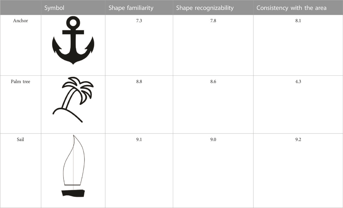
TABLE 1. Results of the survey on symbolic elements for Italian territorial coast.
Accordingly, the representative form of the coastal region of Italy matches the shape of a sail that can serve as the basis of a new shape of pylons, if adequately streamlined.
The identified shape is transformed through a 3D CAD software into a digital model that has to be defined according to the following key points:
• Reproduction fidelity: The 3D models should present only those details that represent the shape. Indeed, it is useless to insert secondary details that could be lost in the subsequent TO, or that would unnecessarily increase the cost of the structure.
• Scale factor: The 3D model must be modeled in full scale to apply the dimensional constraints and the load conditions defined by the standard for HHT power lines.
Figure 6 shows the 3D geometric modeling of the sail-shaped model for the 380-kV line. The model consists of a cylinder with a vertical axis representing the mast and two curved bars supporting the sail’s body. On the latter, the conductors’ passage requires six holes following the regulatory constraints. Furthermore, cylindrical elements, similar to the classic bushings, are introduced in correspondence with the anchoring points of the insulators that suspend the electric energy conductors (highlighted in Figure 6 with green circles) and guard ropes (highlighted in Figure 6 with blue circles). This allows precisely defining the loads’ position and areas where the material should not be removed.
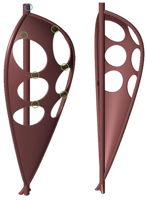
FIGURE 6. 3D CAD model obtained for the representative shape of the 380-kV line.
3.3 Topology optimization and structural analysis for the embodiment design
The aim of the embodiment design is to generate aesthetic models, reminding that the chosen characteristic shapes are structurally efficient and comply with regulatory requirements: this is achieved by TO and structural analysis.
Figure 7 summarizes the information used for the TO of the 3D CAD representative shape. The considered structure comprises the chain of insulators, including their 20 hoods and pins of tempered glass, the terminal tower, and any additional clamps. The material chosen for the pylon is the SAE 304 stainless steel, the most commonly used in these applications. The pylon is constrained by fixing its base. The loads are defined following the reference standard and regulatory requirements, which need all conductors and guard ropes to be intact in the following four load conditions (LC):
• LC#1): the air temperature of −5°C with a wind blowing perpendicular to the power line at 130 km/h;
• LC#2): under the same weather of LC#1, one conductor or one guard string is broken;
• LC#3): the air temperature of –20°C, with the wind blowing perpendicularly to the line at 65 km/h, ice sleeves on conductors or guard ropes;
• LC#4): under the same weather as LC#3, one conductor or guard string is broken.
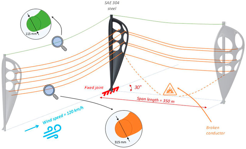
FIGURE 7. Graphical representation of the information used for the TO.
The load exercised by the wind on the pylon is evaluated considering the contributions on the conductors and on the structure itself. Regarding the first contribution, the wind force on the pylon is assumed to be equal to the 10% of the wind force on the conductors. The wind thrust on the structure is evaluated considering it acting perpendicular to two adjacent solid faces, neglecting, conservatively, the fact that the structure is reticular; defined the intensity, the acting forces are distributed on several points of the structure.
The values of the applied loads are evaluated by assuming (Figure 8A):
• Span length = 350 m.
• Diameter of guard ropes = 0.0115 m.
• Conductor diameter = 0.0315 m.
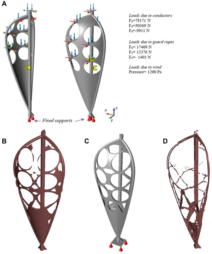
FIGURE 8. TO results. (A) the geometric model, the constraints, and the loads for LC#2 implemented in Optistruct ®; (B) the results of the TO performed to remove about 60% of the material; (C) the new project space by simplifying those details difficult to achieve in practice; (D) results of the final TO.
To perform a TO, the most unfavorable load conditions must apply to the model. In this case, the worst conditions are LC#2 and LC#4, which result in the pylon bending in the wind direction. Between the two, the TO is performed by applying LC#2; the verification of all four load conditions will be performed in the subsequent engineering phase of the detailed design of the structure. Being LC#2 an asymmetrical load, in order to obtain a symmetrical structure, the symmetry to its sagittal plane is added to the constraints of the TO. The TO was carried out by using Altair OptiStruct® software package. Figure 8A shows a screenshot of this software where the geometric model, the constraints, and the loads for LC#2 are represented.
It needs to proceed incrementally to apply the TO to these very large shapes. Therefore, in the first step, considering the complete design volume, a TO is performed to remove about 60% of the material (Figure 8B). Then, a new project space is reconstructed by using the previous phase’s output as a starting point and by simplifying those details that are difficult to achieve in practice (Figure 8C). The TO can be repeated for further material removal (Figure 8D). The results of the TO process consist of a complex model from the geometric point of view; therefore, it is necessary to proceed with engineering the shape. The structural analyses drive this phase. So, for the case study considered here, the resulting geometry is transformed into a lattice structure (Figure 9).
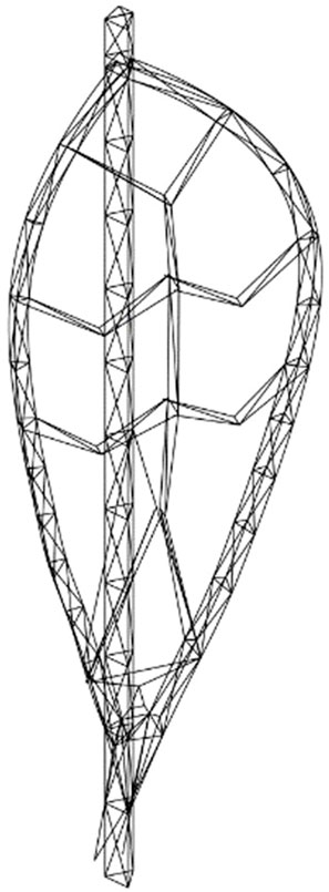
FIGURE 9. Initial reticular structure.
The main mast is modeled as a triangular reticular structure with a vertical axis. Two symmetric curved reticular structures delimit the sail with a triangular section. Reinforcement elements are placed for the connection between the sail and the mast in the lower area; to support the six conductors, beams are inserted.
3.4 Detail design
In this phase, the structure is designed with standardized and commercial components to make the product realization economical and straightforward.
Starting from the structure of Figure 9, the beams are designed iteratively, with each one having a circular hollow section and slimness λ ≤ 15 (following the regulations), and the structure is verified using a Finite Element Method (FEM) analysis under the most severe load condition (LC#2). Also in this case, Altair OptiStruct® was used for the analysis.
The first attempt solution of the iterative method introduced into the FEM is a structure of 1D rod elements, whose characteristic is to work only for axial loads. This property is fully compliant with a theoretical model of a reticular structure. During this preliminary phase, the entire rods were supposed to have the same tube section, whose dimensions satisfy the load condition (1) in the maximum stressed rod element:
where:
σAISI 304 = the yield strength of AISI 304 steel.
S.F. = 4 is a safety factor; its value is fixed to consider the fatigue effects and most severe and not predictable load conditions.
These considerations determine an admissible value of stress σ_amm of 80 MPa for the road elements.
The FEM analysis results of this first attempt structure evidenced that, with these conditions, most elements are significantly oversized. Therefore, this initial solution supplies (Figure 10A) the input for the iterative process that aims to optimize the dimensions of each element. The symmetry constraint is applied to a user-defined plane. The forces acting along each rod were extracted into a spreadsheet and sorted in descending order. Then five commercial tube sections were chosen, with a diameter progressively decreasing (see legend of Figure 10). Considering the descending order previously defined, each rod was assigned the minimum size section satisfying the load condition (1). The optimization required three iterations to converge because of the change in stiffness and mass of the entire structure during the different iterations (Figure 10B). At the end of the optimization process, the total mass was reduced from the initial one of 300 tons–30 tons. Figure 10B depicts the final configuration of rod elements (IT3 results), whose colors refer to the legend. Figure 11 shows the stress analysis (Figure 11A) and displacements (Figure 11B) for the final configuration under LC#2. The maximum stress values are about one order of magnitude lower than the limit values for AISI 304. Lower stress values and displacements were verified for the other load conditions.
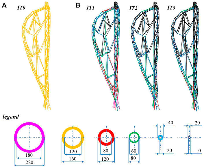
FIGURE 10. (A) Initial reticular structure (ITO); (B) Results of the iterative optimization from ITO to the final one (IT3).
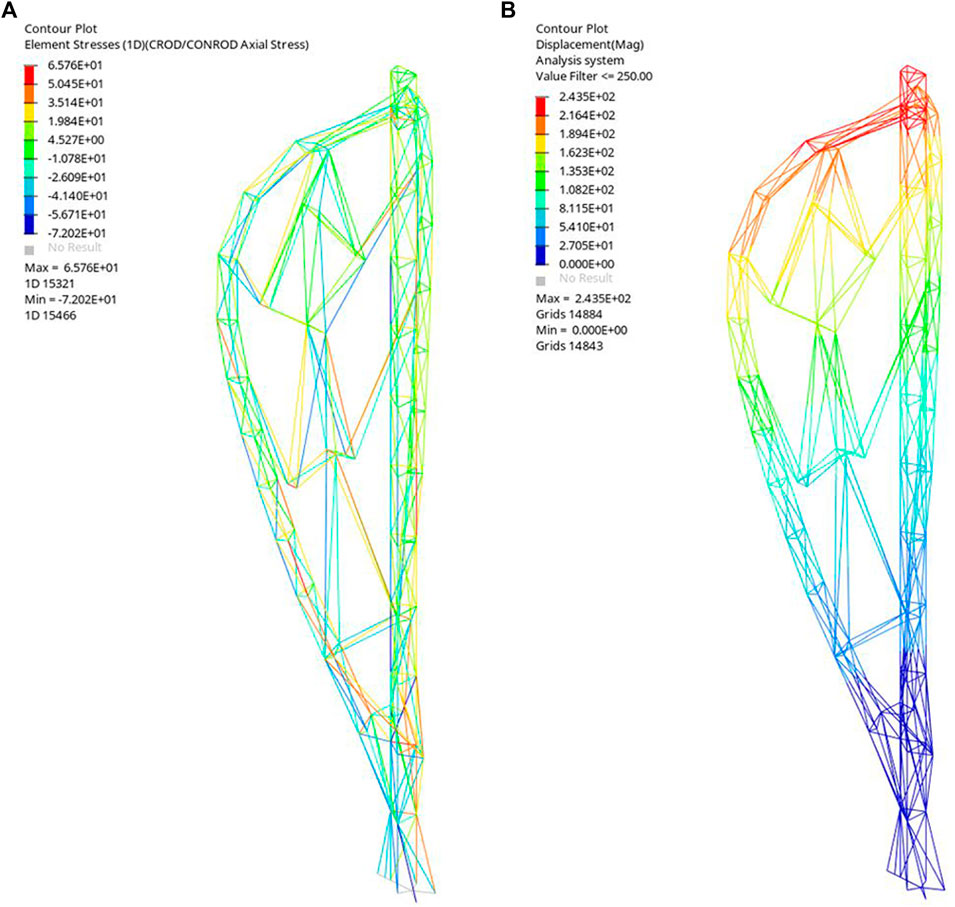
FIGURE 11. The displacement (A) and stress results (B) for the LC#2 applied to the final configuration (IT3 of Figure 9).
The lines of the beam structure have been exported from the Altair OptiStruct® software, imported, and modeled in a 3D CAD using specifically designed functions. Figure 12 shows the render of the lattice structure where the colors are linked to the beams’ dimensions according to the reported legend; this allows to highlight differences in diameter better. In the same figure, the two image magnifications show the distribution of different beam sizes in the optimized structure.
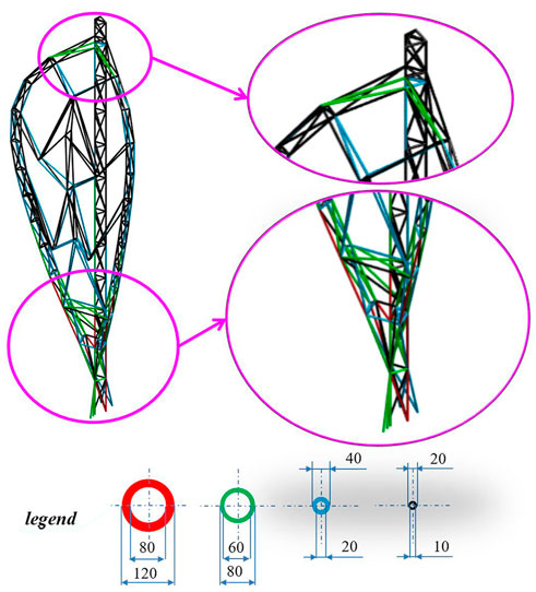
FIGURE 12. Render of the structure.
In the proposed detailed design, all the beams are connected by welding. Both to protect the welds and improve the appearance, following the state-of-the-art analysis, sheet metals are applied to cover the lattice structures of the mast and sail. Figure 13 shows a rendering of the proposed final pylon.
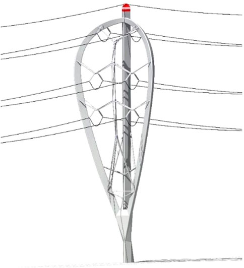
FIGURE 13. Render of the proposed pylon.
4 Discussion and conclusion
The enhancement of the visual quality of above-ground structures, in particular vertical ones such as pylons, is still an open issue for two main reasons:
• The visual impact is related to subjective perception.
• The enhancement of the visual quality must not cause non-compliance with other requirements such as regulatory and industrial feasibility.
The literature analysis shows that, on the one hand, the focus of most of the studies, although recent, is the integration of the structural and morphological aspect, albeit limited to the conceptual phase, as a starting point for the following design phases. On the other hands, other studies including the entire design process have led to the development of new pylon designs that only partially complies with all the mandatory and aesthetical requirements. So, for example, some pylon designs are stopped at the conceptual phase as in Cotton and Devine-Wright (2013) for non-compliance with regulatory, safety, and the impossibility of its engineering. On the contrary, the new designs of installed pylons do not completely satisfy the guidelines for enhancing the visual quality. This paper presented a systematic method for designing pylons with improved visual quality to overcome these limitations. The suggested approach considers all possible requirements concerning the measures to enhance the visual quality, including regulatory, industrial feasibility, and social components. Regarding the last one, among all the results of the studies reported in the literature about the social and psychological factors that can influence the perception of visual impact, the following were taken into account since they are considered the most important ones:
• The typical lattice structures, even if they are optimized in terms of cost of material, loads, transportation, erection, and maintenance, are perceived with a negative visual impact.
• An important mitigation strategy includes involving residents as decision-makers from the early design stages.
• Custom-designed structures with an improved visual impact are recommended in key areas with high landscape interest since they should blend more effectively with the surroundings.
The proposed method includes these guidelines as well as all the other sources of requirements already early in the design phase and comprises the following steps:
• The technical specifications are identified through the analysis of the regulatory and standard context, the landscape impact, the potential customers’ needs, and functional analysis.
• A representative shape of the geographical area is identified.
• A 3D CAD model of the pylon is modeled following the previous step.
• The 3D CAD model is optimized to develop a geometry that respects the limits set by the previously identified requirements while being structurally effective.
• The optimized 3D model is embodied into an industrial product that can be produced and installed while preserving the characteristics of the original shape.
The approach has been applied to a particularly critical situation: the design of a new electricity pylon for a 380-kV line to be installed in the coastal territory of a Mediterranean country like Italy. The application of the method led to the detailed design of a pylon shaped like a sail (Figure 13), chosen as symbolically representative of the Italian coast. The engineering phase has been performed by assembling standard lattice components with welded connections.
The proposed geometry has been compared with the traditional lattice pylon and the “Rosental” to evaluate its visual impact on the coastal landscape. The comparison is performed by rendering the analyzed pylons using an image of the coastal landscape as the environment (Figure 14). The comparison is performed according to the preferences of 72 people (other than those interviewed for the choice of characteristic geometry in Section 3.2), between the ages of 18 and 65, from different social backgrounds who live in coastal areas of four different Italian regions (two in southern Italy and two in the north). From the data analysis, 58.33% of the interviewees consider that the geometry that best fits the coastal territory is the proposed one.
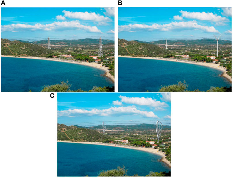
FIGURE 14. Rendering of standard pylon (A), Rosental pylon (B), and proposed pylon (C) in a coastal landscape.
In conclusion:
• The technical specifications reported in Figure 5 have been met.
• A lightweight structure constructed using a lattice structure and covered by sheet metal is achieved by applying the suggested method.
• Since this structure employs an additional 15%–20% of trusses and sheet metals partially cover it, the cost for materials (e.g., the extruded profiles), as well as mechanical joints (e.g., fasteners or welding operations of the new structures) is higher when compared to the classic design pylon.
• The results of the proposed method, applied to the critical situation discussed here, showed its potential in defining the design for structures with enhanced visual quality, satisfying all the mandatory and functional requirements.
Again, to this last aim, future works will focus on applying the method to other above-ground structures and in different contexts where symbolic shapes can be identified as representative of the landscape, the environment, or the cultural context. Future efforts will be addressed to the specific economic evaluations for the optimization of the production process to define the minimum cost and compare it with that of the state-of-the-art.
Data availability statement
The original contributions presented in the study are included in the article/supplementary material, further inquiries can be directed to the corresponding author.
Author contributions
Conceptualization, LA and EG; methodology, LA, FG, and EG; software, LA and EG; validation, LA, RF, FG, and EG; writing—original draft preparation, LA, RF, FG, and EG; writing—review and editing, LA, RF, FG, and EG; supervision, LA and RF. All the authors have reviewed and edited the manuscript.
Conflict of interest
The authors declare that the research was conducted in the absence of any commercial or financial relationships that could be construed as a potential conflict of interest.
Publisher’s note
All claims expressed in this article are solely those of the authors and do not necessarily represent those of their affiliated organizations, or those of the publisher, the editors and the reviewers. Any product that may be evaluated in this article, or claim that may be made by its manufacturer, is not guaranteed or endorsed by the publisher.
References
Atkinson, G., Day, B., and Mourato, S. (2006). “Measuring the visual disamenity from overhead electricity transmission lines,” in Environmental valuation in developed countries: Case studies. Editor D. Peirce (UK: Edward Elgar Publishing), 213–239.
Bici, M., Broggiato, G. B., and Campana, F. (2017). “Topological optimization in concept design: Starting approach and a validation case study,” in Advances on mechanics, design engineering and manufacturing. Lecture notes in mechanical engineering. Editors B. Eynard, V. Nigrelli, S. Oliveri, G. Peris-Fajarnes, and S. Rizzuti (Cham: Springer).
Brütting, J., Senatore, G., Schevenels, M., and Fivet, C. (2020). Optimum design of frame structures from a stock of reclaimed elements. Front. Built Environ. 6, 27. doi:10.3389/fbuil.2020.00057
Buonamici, F., Carfagni, M., Furferi, R., Governi, L., Lapini, A., and Volpe, Y. (2018). Reverse engineering modeling methods and tools: A survey. Computer-Aided Des. Appl. 15 (3), 443–464. doi:10.1080/16864360.2017.1397894
Byrne, J., Fenton, M., Hemberg, E., McDermott, J., and O’Neill, M. (2015). Optimising complex pylon structures with grammatical evolution. Inf. Sci. 316, 582–597. doi:10.1016/j.ins.2014.03.010
Chen, J., Yuan, F., and Jiang, L. (2014). “Optimal design of transmission line tower based intelligent selection,” in Proc. Canadian Society for Mechanical Engineering Int. Congr, Toronto, Canada, June 2014.
Cicconi, P., Manieri, S., Nardelli, M., Bergantino, N., Raffaeli, R., and Germani, M. (2020). A constraint-based approach for optimizing the design of overhead lines. Int. J. Interact. Des. Manuf. 14 (3), 1121–1139. doi:10.1007/s12008-020-00680-x
Company, P., Naya, F., Contero, M., and Camba, J. D. (2020). On the role of geometric constraints to support design intent communication and model reusability. CAD&A 17 (1), 61–76. doi:10.14733/cadaps.2020.61-76
Cotton, M., and Devine-Wright, P. (2013). Putting pylons into place: A UK case study of public perspectives on the impacts of high voltage overhead transmission lines. J. Environ. Plan. Manag. 56 (8), 1225–1245. doi:10.1080/09640568.2012.716756
Dalpadulo, E., Gherardini, F., Pini, F., and Leali, F. (2020). Integration of topology optimisation and design variants selection for additive manufacturing-based systematic product redesign. Appl. Sci. Switz. 10 (21), 1–13. doi:10.3390/app10217841
Dapogny, C., Faure, A., Michailidis, G., Allaire, G., Couvelas, A., and Estevez, R. (2017). Geometric constraints for shape and topology optimization in architectural design. Comput. Mech. 59 (6), 933–965. doi:10.1007/s00466-017-1383-6
De Souza, R. R., Miguel, L. F. F., Lopez, R, H., Miguel, L. F. F., and Torii, A. J. (2016). A procedure for the size, shape and topology optimization of transmission line tower structures. Eng. Struct. 111, 162–184. doi:10.1016/j.engstruct.2015.12.005
Devine-Wright, P., and Batel, S. (2013). Explaining public preferences for high voltage pylon designs: An empirical study of perceived fit in a rural landscape. Land Use Policy 31, 640–649. doi:10.1016/j.landusepol.2012.09.011
Di Angelo, L., Gherardini, F., Di Stefano, P., and Leali, F. (2020). Design for visual quality enhancement of artificial infrastructure facilities: An application to electricity pylons. Appl. Sci. 10 (3), 1131. doi:10.3390/app10031131
Environmental Protection Department (2013). HKSAR Landscape and visual impact assessments. Chapter 6 https://www.epd.gov.hk/eia/register/report/eiareport/eia_1852010/EIA/HTML/Rev%20F_Sec%206_html.htm (accessed November 4, 2019).
Foster and Partners (2010). ENEL power pylons. https://www.fosterandpartners.com/projects/enel-power-pylons/ (accessed November 4, 2019).
Frearson, A. (2015). New pylons by architect Erik Bystrup will "become part of the landscape. Dezeen: https://www.dezeen.com/2015/06/02/new-t-pylon-erik-bystrup-united-kingdom-coutryside-more-beautiful-national-grid/(accessed November 4, 2019).
Gherardini, F., Renzi, C., and Leali, F. (2017). A systematic user-centred framework for engineering product design in small- and medium-sized enterprises (SMEs). Int. J. Adv. Manuf. Technol. 91 (5–8), 1723–1746. doi:10.1007/s00170-016-9857-9
Goldbach, A-K., Bauer, A. M., Wüchner, R., and Bletzinger, K-U. (2020). CAD-integrated parametric lightweight design with isogeometric B-rep analysis. Front. Built Environ. 6. doi:10.3389/fbuil.2020.00044
Guo, H. Y., and Li, Z. L. (2011). Structural topology optimization of high-voltage transmission tower with discrete variables. Struct. Multidisc. Optim. 43 (6), 851–861. doi:10.1007/s00158-010-0561-3
Gythiel, W., Mommeyer, C., Raymaekers, T., and Schevenels, M. (2020). A comparative study of the structural performance of different types of reticulated dome subjected to distributed loads. Front. Built Environ. 6. doi:10.3389/fbuil.2020.00056
Hardie, G. J. (1988). Community participation based on three-dimensional simulation models. Des. Stud. 9 (1), 56–61. doi:10.1016/0142-694x(88)90026-9
He, Y., Zhao, Z-L., Cai, K., Kirby, J., Xiong, Y., and Xie, Y. M. (2022). A thinning algorithm based approach to controlling structural complexity in topology optimization. Finite Elem. Analysis Des. 207, 103779. doi:10.1016/j.finel.2022.103779
Hofer, P., Sturm, F., and Wehrle, E. (2022). Topology optimization of a cableway pylon with assessment of uncertain loading. Proc. Appl. Math. Mech. 21 (3), 1–13. doi:10.1002/pamm.202100263
Kempenaar, A., and van den Brink, A. (2018). Regional designing: A strategic design approach in landscape architecture. Des. Stud. 54, 80–95. doi:10.1016/j.destud.2017.10.006
Kim, H., Querin, O. M., and Steven, G. P. (2002). On the development of structural optimisation and its relevance in engineering design. Des. Stud. 23 (1), 85–102. doi:10.1016/s0142-694x(01)00017-5
Koglin, H. J., and Gross, M. (1988). “Representation of planned over headlines – The optical impression on the landscape,” in Proc. Int. Conf. Overhead Line Design and Construction: Theory and Practice, 151–155.
Li, Y., Lai, Y., Lu, G., Yan, F., Wei, P., and Xie, Y. M. (2022a). Innovative design of long-span steel–concrete composite bridge using multi-material topology optimization. Eng. Struct. 269, 114838. doi:10.1016/j.engstruct.2022.114838
Li, Z., Ye, J., Gao, B., Wang, Q., Quan, G., and Shepherd, P. (2022b). Digital and automatic design of free-form single-layer grid structures. Automation Constr. 133, 104025. doi:10.1016/j.autcon.2021.104025
Lin, K., He, Y., Yang, Y., and Xiong, L. (2021). From topology optimization to complex digital architecture: A new methodology for architectural morphology generation. Adv. Civ. Eng. 2021, 1–13. doi:10.1155/2021/6839627
López, C., Baldomir, A., and Hernandez, S. (2017). The relevance of reliability-based topology optimization in early design stages of aircraft structures. Struct. Multidisc. Optim. 57, 417–439. doi:10.1007/s00158-017-1740-2
Luck, R. (2018). Participatory design in architectural practice: Changing practices in future making in uncertain times. Des. Stud. 59, 139–157. doi:10.1016/j.destud.2018.10.003
Mo, W., Wei, C., Liu, S., Tian, A., Zhou, M., and Jin, S. (2022). Topology optimization of numerical control rotary table with manufacturing constraints. Front. Mech. Eng. doi:10.3389/fmech.2022.1032832
Müller, O., Albers, A., Ilzhöfer, B., and Häußler, P. (1999). “Multidisciplinary shape and topology optimization and its integration in the product design process for the effective development of competitive products,” in International Conference on Engineering Design ICED 99, Munich, Germany, August 24–26, 1999(Garching), 655–670.2
Nyirenda, P. J., and Bronsvoort, W. F. (2008). Numeric and curve parameters for freeform surface feature models. Computer-Aided Des. 40 (8), 839–851. doi:10.1016/j.cad.2008.03.003
Pahl, G., and Beitz, W. (1996). in Engineering design: A systematic approach. trans. Editors K. Wallace, L. Blessing, and F. Baurt. 2nd ed. (London: Springer-Verlag), 125–143.
Palmer, J. F. (2022b). A diversity of approaches to visual impact assessment. Land 11, 1006. doi:10.3390/land11071006
Palmer, J. F. (2022a). Deconstructing viewshed analysis makes it possible to construct a useful visual impact map for wind projects. Landsc. Urban Plan. 225, 104423. doi:10.1016/j.landurbplan.2022.104423
Priestley, T., and Evans, G. W. (1996). Resident perceptions of a nearby electric transmission line. J. Environ. Psychol. 16, 65–74. doi:10.1006/jevp.1996.0006
Reed, B. (2011). An introduction to visual impact assessment. Water, Leicestershire, United Kingdom: Engineering and Development Centre School of Civil and Building Engineering Loughborough University.
Shea, K., and Smith, I. F. (2006). Improving full-scale transmission tower design through topology and shape optimization. J. Struct. Eng. 132 (5), 781–790. doi:10.1061/(asce)0733-9445(2006)132:5(781)
Sumper, A., Boix-Aragonès, O., Villafáfila-Robles, R., Bergas-Jané, J., and Ramírez-Pisco, R. (2010). Methodology for the assessment of the impact of existing high voltage lines in urban areas. Energy Policy 38, 6036–6044. doi:10.1016/j.enpol.2010.05.059
Turnbull, W. M., and Gourlay, I. (1987). Visual impact analysis: A case study of a computer-based system. Computer-Aided Des. 19 (4), 197–202. doi:10.1016/0010-4485(87)90069-8
United States Department of the Interior (2013). Best management practices for reducing visual impacts of renewable energy facilities on BLM-administered lands. Cheyenne, WY: Bureau of Land Management. Cheyenne, Wyoming, 342.
Urick, B., Marussig, B., Cohen, E., Crawford, R. H., Hughes, T. J. R., and Riesenfeld, R. F. (2018). Watertight boolean operations: A framework for creating CAD-compatible gap-free editable solid models. Computer-Aided Des. 115, 147–160. doi:10.1016/j.cad.2019.05.034
Wang, Y., Du, W., Wang, H., and Zhao, Y. (2021). Intelligent generation method of innovative structures based on topology optimization and deep learning. Materials 14, 7680. doi:10.3390/ma14247680
Xiaoyu, L., Yue, W., Airong, C., Bo, L., and Haibo, L. (2021). Form finding and aesthetic design for pylons of cable-supported bridges. Struct. Eng. Int. 31 (4), 468–476. doi:10.1080/10168664.2020.1870056
Keywords: design method, topology optimization, computer-aided tool, pylon, visual impact, landscape impact
Citation: Di Angelo L, Furferi R, Gherardini F and Guardiani E (2022) The integration of morphological design and topology optimization to enhance the visual quality of electricity pylons. Front. Mech. Eng 8:1061905. doi: 10.3389/fmech.2022.1061905
Received: 05 October 2022; Accepted: 05 December 2022;
Published: 16 December 2022.
Edited by:
Jiewu Leng, Guangdong University of Technology, ChinaCopyright © 2022 Di Angelo, Furferi, Gherardini and Guardiani. This is an open-access article distributed under the terms of the Creative Commons Attribution License (CC BY). The use, distribution or reproduction in other forums is permitted, provided the original author(s) and the copyright owner(s) are credited and that the original publication in this journal is cited, in accordance with accepted academic practice. No use, distribution or reproduction is permitted which does not comply with these terms.
*Correspondence: Rocco Furferi, rocco.furferi@unifi.it