Design and Analysis of Prosthetic Heart Valves and Assessing the Effects of Leaflet Design on the Mechanical Attributes of the Valves
 Jaafar Ghanbari
 Amirhossein Dehparvar
 Amirhossein Zakeri
- Mechanical Engineering Department, Qom University of Technology, Qom, Iran
Prosthetic heart valves are commonly used as a treatment for aortic valve deficiencies. The performance of these prosthetic valves should be in accordance with the natural heart valve with respect to opening and closing, blood flow, and vortex formation. These performance parameters depend on the design of leaflets and overall geometrical parameters of the valve. To better understand the effects of leaflet design on the performance of the valve, we have carried out fully coupled fluid–structure interaction analyses of opening and closing of prosthetic heart valves with various leaflet designs. Maximum stress, valve opening, and flow stream pattern are obtained for different valve designs and used to assess the performance of the valves. The results show that the stress and the valve opening depend on the curvature and the inclination of the leaflets. A 3D model is designed based on the obtained results, and a full FSI analysis is performed to assess its performance. The results show that the presented design gives better values for valve opening area and leaflet stresses than that in the published data.
Introduction
Heart valve diseases like valvular stenosis or valvular insufficiency are a significant cause of global mortality, especially in Western countries. The human heart has two types of valves: mitral and aortic valves in its left compartment, which regulate unidirectional blood flow during the cardiac cycle. The mitral valve controls the blood flow into the ventricle and has two leaflets, and the aortic valve controls the blood flow into the aorta and has three leaflets. These valves operate passively by their leaflet movements (deformations) merely by the pressure gradient in the blood flow during a cardiac cycle. Because of various diseases caused by different agents such as bacterial infection, congenital heart defects, and rheumatic fever, the natural heart valve is subject to replacement by animal or prosthetic heart valves. Animal originated valves, which are called biological heart valves, are mainly bovine or porcine valves which are chemically treated to adapt human body (Liao et al., 1992). These valves are susceptible to tissue degeneration and calcification and, as a result, subject to failure 10–15 years after implantation (Siddiqui et al., 2009). Another problem with these valves is the fact that they have no uniform structure and properties like thickness and mechanical strength due to the creatures’ differences. Mechanical prosthetic heart valves solve this shortcoming of biological valves, and because of their durability, some studies (Zakaria et al., 2017) show that almost 60% of worldwide annual heart valve replacements use mechanical heart valves.
Mechanical heart valve designs have progressed in recent decades. The early designs of the mechanical valves, caged ball valves and tilting disc valves, caused several problems such as hemolysis of red blood cells and platelet activation because of their blood flow patterns (Black et al., 1983). Polymeric heart valves have gained the researchers’ interest because of their similarity with the natural heart valve in their mechanical behavior and controllability on the biological and biocompatibility characteristics. Different polymers are used as the base material for synthetic heart valves such as polyester (Vaesken et al., 2014; Meddahi-Pelle et al., 2021; Zhou et al., 2021), polyurethane (Gasparotti et al., 2018; MohmadSaberi, 2020; Ataee et al., 2021; Kazeroni et al., 2021), thermoplastic polyurethane (Fallahiarezoudar et al., 2017a; Fallahiarezoudar et al., 2017b; Zuke, 2017), and ultrahigh–molecular weight polyethylene (Thomas and Jayabalan, 2008; Zhou et al., 2021).
Designing an appropriate synthetic heart valve requires assessing its performance during a cardiac cycle from different contexts. From the mechanical design point of view, both leaflet deformation/stress and blood flow pattern should be studied. As the leaflet is under fluctuating stress, large fatigue life requires lower stress values in addition to the flexibility to open and close the flow path as the main function of the heart valve when we consider the deformation requirements. Compared with in situ investigations, numerical simulations give in-depth, high-resolution values in parameters as functions of time and position and, as a result, complete information on the performance of the synthetic heart valves under operation. Because of the nature of the valves, fluid–structure interaction (FSI) simulations with two-way coupling are the best analysis methods for this scenario (Bailoor et al., 2021; Geronzi et al., 2021). Leaflets and the vessel are modeled as solid parts with Cauchy equations of motion, while the blood is modeled as the fluid part with Navier–Stokes equations of motion, having deformable boundaries (the solid part) with two solid and fluid equations being solved simultaneously. Borazjani (2013) developed an immersed boundary-finite element model to study the FSI of a heart valve and studied the blood flow pattern in the mechanical and bioprosthetic heart valves. Gilmanov and Sotiropoulos (2015) compared the blood flow pattern in an aorta with bicuspid and trileaflet valves.
One of the early works on the analysis of the bioprosthetic heart valves is the study by Arcidiacono et al. (2005). They determined the stress distribution on the leaflets made with the bovine pericardium during a full cardiac cycle. They assumed a linear elastic orthotropic material model for the leaflets and concluded that the orthotropy affects the leaflet performance and its stress values. Driessen et al. (2007) studied the deformation of tissue-engineered heart valve leaflets under pressure and culturing conditions. They concluded that stresses increase with the culture time, while strains decrease. Kim et al. (2007) studied the dynamic response of a bioprosthetic heart valve using a shell model with the Fung constitutive model for leaflets. Lee et al. (2020) studied a porcine- and a bovine-based bioprosthetic heart valve using FSI simulations and compared the results with a model under a pulse duplicator. They showed a good agreement between experimental and numerical results for the leaflet deformation and dynamic valve area. Kerr and Gourlay (2020) investigated an expandable valve design using FSI simulations. Park et al. (2021) reviewed various study techniques of the prosthetic heart valves and categorized them. Nestola et al. (2021) proposed an FSI model to study the dynamic behavior of the bioprosthetic heart valves with the goal of optimizing the stress distribution on the leaflets. Recently, a review on the numerical studies published so far is presented by Abbas et al. (2022). Hsu et al. (2015) studied FSI of a prosthetic heart valve using parametric design and compared the results of the FSI simulation with those of structural dynamic simulation of the valve under pressure loading.
Gulbulak et al. (2020) studied the effect of the generating curve of the leaflet geometry on the orifice area of the polymeric heart valve. They used a three-point generating curve of the leaflet geometry and obtained their best parameters using the Taguchi method.
In this article, a prosthetic valve design is presented by studying the effects of the geometric parameters on the overall performance of the valve. To this end, first, the effects of the leaflet curvature and its inclination on the valve opening area and maximum von Mises stress of the leaflet are obtained by some 2D simulations. Then, a 3D model is constructed based on the results obtained from the 2D analyses. At this stage, some incremental changes are made on the design variables, and the simulation of the valve is done for a fraction of the total time of the cardiac cycle. The final value is fixed based on the obtained results of the incremental studies. Finally, the full design is analyzed, and the performance parameters are compared with the published articles.
Leaflet Design
Mechanical performance of the prosthetic heart valves depends on the design parameters of the leaflets such as the curvature, height, and the slope at the skirt location. To come up with an appropriate design, first, we conduct a preliminary 2D study on the effects of the leaflet slope at the skirt on the mechanical parameters such as the valve opening and stress values on the leaflets. It is noted that fully coupled FSI analyses are carried out using the Comsol Multiphysics finite element software package. Moving mesh on the fluid domain is controlled by arbitrary Lagrangian–Eulerian (ALE) formulation. Comsol couples the solid and fluid domains on the common boundaries by transferring displacements, velocities, and pressure loads at every step taken by the solver to solve the governing equations of the solid and fluid domains. According to the loading conditions, we have applied the blood velocity at the inlet of the vessel, as shown in Figure 1. At the outlet, the pressure is set to be zero. The valve material is chosen to be the same as chosen by Luraghi et al. (2017), poly(styrene–ethylene–propylene–styrene) (SEPS) block copolymers with 22% polystyrene fraction for comparison purposes. The polymer has a density of 830 kg/m3, Young’s modulus equal to 3.2 MPa, and Poisson’s ratio equal to 0.4. The blood is modeled as the Newtonian fluid with a density of 1,060 kg/m3.
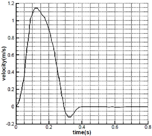
FIGURE 1. Inlet velocity as a function of time (Avanzini, 2017).
Four models of the leaflets with different slopes and curvatures are considered, as shown in Figure 2. Leaflet designs L1 and L2 have linear profiles with different slopes at the skirt: 40° for L1 and 50° for L2. L3 design has a circular curvature, and L4 has a parabolic curvature to give insights on the effects of the curvature and slope on the performance metrics of the prosthetic heart valve.
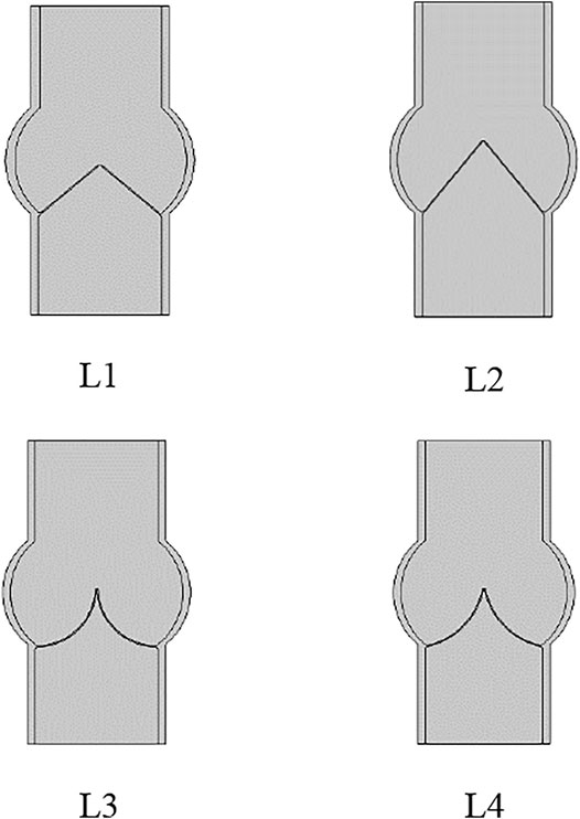
FIGURE 2. Leaflet designs with linear profile and slope angle equal to 40° and 50° for L1 and L2, and circular and parabolic curvatures for L3 and L4, respectively.
Maximum opening of the leaflets is shown in Figure 3. It follows that the leaflet design L2 results in a larger opening, compared with other designs. In addition to the temporary value of the valve opening, the averaged opening area of the valves is shown in Figure 4. The results show that a larger slope at the skirt of the valve results in a larger valve opening area. In addition, for leaflets to have large opening area, the profile should be linear, at least at the skirt area of the valve.
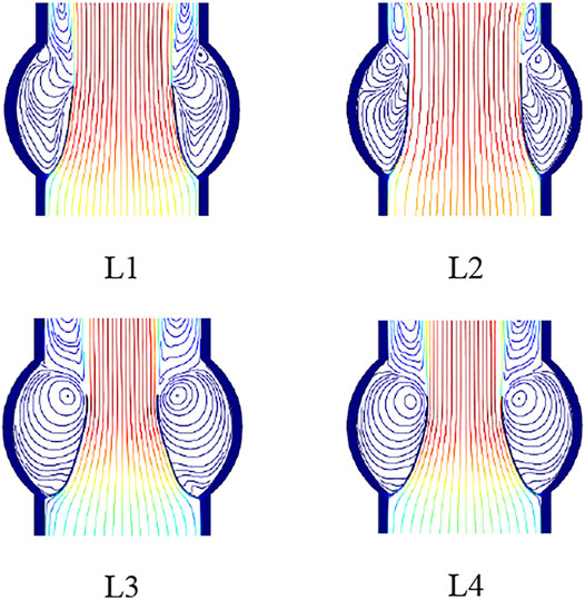
FIGURE 3. Leaflets at maximum opening with the streamline of the blood.
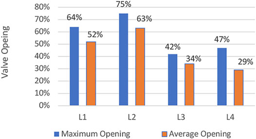
FIGURE 4. Valve opening area for the leaflet designs.
Maximum von Mises stress on the leaflets as a function of time during a cardiac cycle is illustrated in Figure 5. From the stress point of view, it is observed that leaflets with linear profile have smaller stress values.
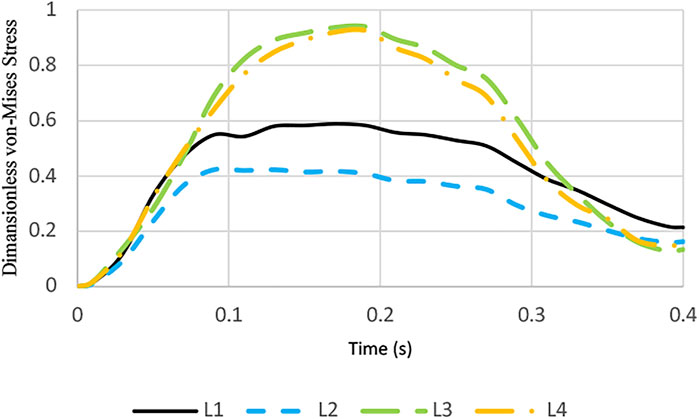
FIGURE 5. Dimensionless von Mises stress during a cardiac cycle.
From these 2D simulations, we can conclude that the leaflet should have a larger slope at the skirt area of the valve and as linear as possible at that location so that the valve has a larger opening area and smaller stress values during the operation of the valve.
Prosthetic Valve Design
Based on the published studies and the 2D simulation results in the previous section, a prosthetic heart valve with the leaflets having parabolic curvature at the center and linear profile at the skirt area with the parameters listed in Table 1 is constructed, as shown in Figure 6. This way, the advantages of the linear profile with a large slope at the skirts are employed, while the rest of the profile with the parabolic curvature fills the cross-section of the vessel to yield the needed geometry of the valve as close to the natural valves as possible. Because of the difficulty of running a full simulation of the models, incremental design changes are applied to the model and a fraction of the cardiac cycle is simulated to get the results. So, all the parameters are not available for the intermediate designs.
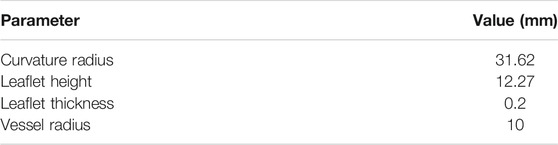
TABLE 1. Design parameters of the prosthetic valve.
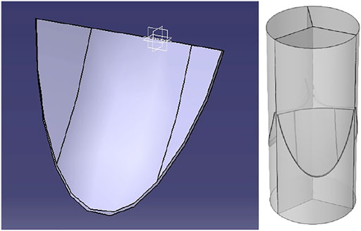
FIGURE 6. Prosthetic heart valve design.
For the 3D simulations, similar boundary conditions discussed in the previous section are applied to the model. Blood is modeled as a Newtonian fluid. The large eddy simulation (LES) turbulence model is taken into account for turbulence modeling of the flow. Fluid region mesh is smoothed and moved by using a Yeoh mesh smoothing model during the FSI solution steps. The solution step is considered to be a transient solution with inertial effects activated. The fully coupled explicit solver is employed to get the results for a full cardiac cycle.
In LES, the larger three-dimensional, unsteady eddies are resolved, whereas the effect of the smaller eddies is modeled. The velocity and pressure fields are divided into resolved and unresolved scales. Denoting the fields containing all scales with capital letters, the decomposition can be expressed as follows:
Inserting Eq. 1 into the incompressible form of the Navier–Stokes equation and the continuity equation yields the following equation:
In Eq. 2, f is the applied traction force on the boundary ∂Ω of the spatial domain Ω, and the stresses in the last term on the right-hand side are the resolved non-linear advection term, the two cross-stresses, and the Reynolds stress. In the residual-based variational multiscale (RBVM) method, the unresolved velocity and pressure scales are modeled in terms of the equation residuals for the resolved scales as follows:
and the momentum and continuity equation residuals are given as follows:
and the intrinsic timescales are given as follows:
Here, C1, C2, and C3 are constants depending on the temporal scheme, the shape of the element, and the order of the shape functions, respectively. G is the covariant metric tensor.
The fluid–structure interaction (FSI) couplings appear on the boundaries between the fluid and the solid. The physics interface of the Comsol Multiphysics uses an ALE method to combine the fluid flow formulated using an Eulerian description and a spatial frame with solid mechanics formulated using a Lagrangian description and a material (reference) frame. The fluid flow is described by the Navier–Stokes equations which provide a solution for the velocity field ufluid. The total force exerted on the solid boundary by the fluid is the negative of the reaction force on the fluid as follows:
where p denotes pressure, μ the dynamic viscosity for the fluid, n the outward normal to the boundary, and I the identity matrix. Because the Navier–Stokes equations are solved in the spatial (deformed) frame while the structural mechanics interfaces are defined in the material (undeformed) frame, a transformation of the force is necessary. This is done according to the following equation:
where dv and dV are the mesh element scale factors for the spatial frame and the material (reference) frame, respectively. The coupling in the other direction consists of the structural velocity, where dv and dV are the mesh element scale factors for the spatial frame and the material (reference) frame, respectively.
For every finite element simulation, mesh independency or convergence should be inspected. To this end, a series of simulations with various element sizes (Table 2) are performed. It is noted that since full simulations are very time-consuming because of the nature of the problem, only a fraction of the step time (0.01 s) is taken into account for mesh convergence study.
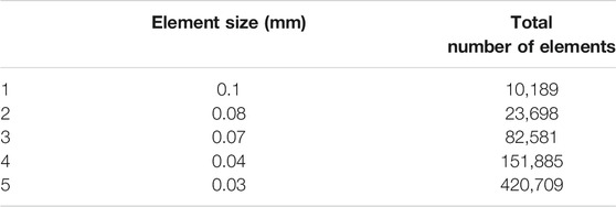
TABLE 2. Mesh convergence models.
The maximum von Mises stress is obtained for the models with the element sizes listed in Table 2, and the results are shown in Figure 7. It is observed that the last two models show nearly identical results for the maximum stress on the leaflets. So, we adopt the element size equal to 0.03 mm for the full analysis.

FIGURE 7. Mesh convergence results.
Results and Discussions
The PC used for the simulation is a workstation with an Intel Xeon CPU with 16 cores and 64 GB of RAM. Each full cycle simulation took 12 h to complete. As mentioned earlier, the design of the leaflet is obtained by incremental changes in the geometric parameters of the leaflets and observing the effects on the overall performance of the valve. The stress distributions of the leaflets are shown in Figure 8 during a full cardiac cycle. The contour legend bar is common for all time steps with the unit of MPa for the von Mises stress. It is observed that the regions with maximum stress vary as a function of time, except for the corners of the leaflets as they experience large bending moment during the valve operation.
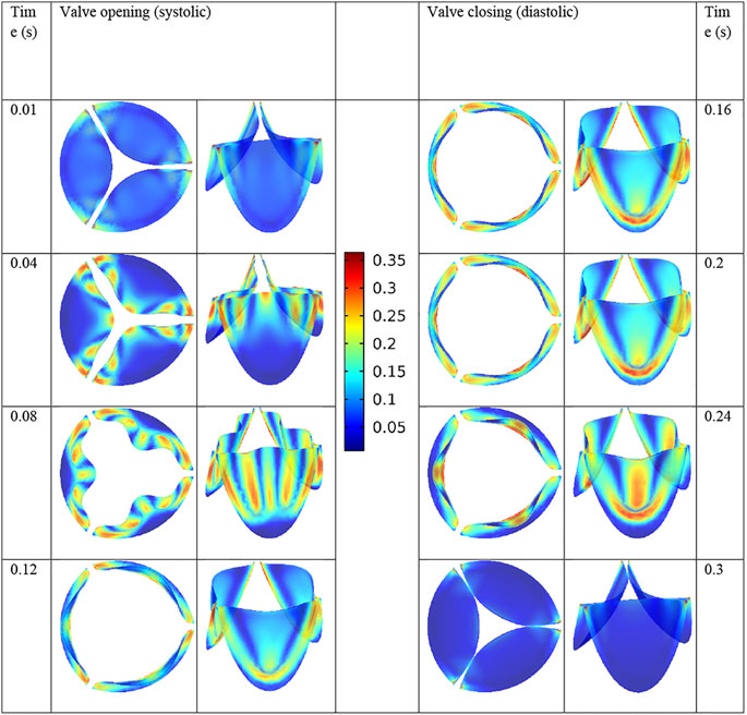
FIGURE 8. von Mises stress distribution on the leaflets throughout a cardiac cycle.
The maximum von Mises stress on the leaflets is equal to 0.36 MPa in the present valve design. Luraghi et al. (2017) reported the stress value of 0.85 MPa for their valve design. Note that for comparison purposes, we have used the same polymer as them in our simulations.
The flow field of the blood during the valve opening is shown in Figure 9 at different time steps. It is observed that while small vortices form from the beginning of the valve opening, considerable vortices appear as the valve approaches its full opening.
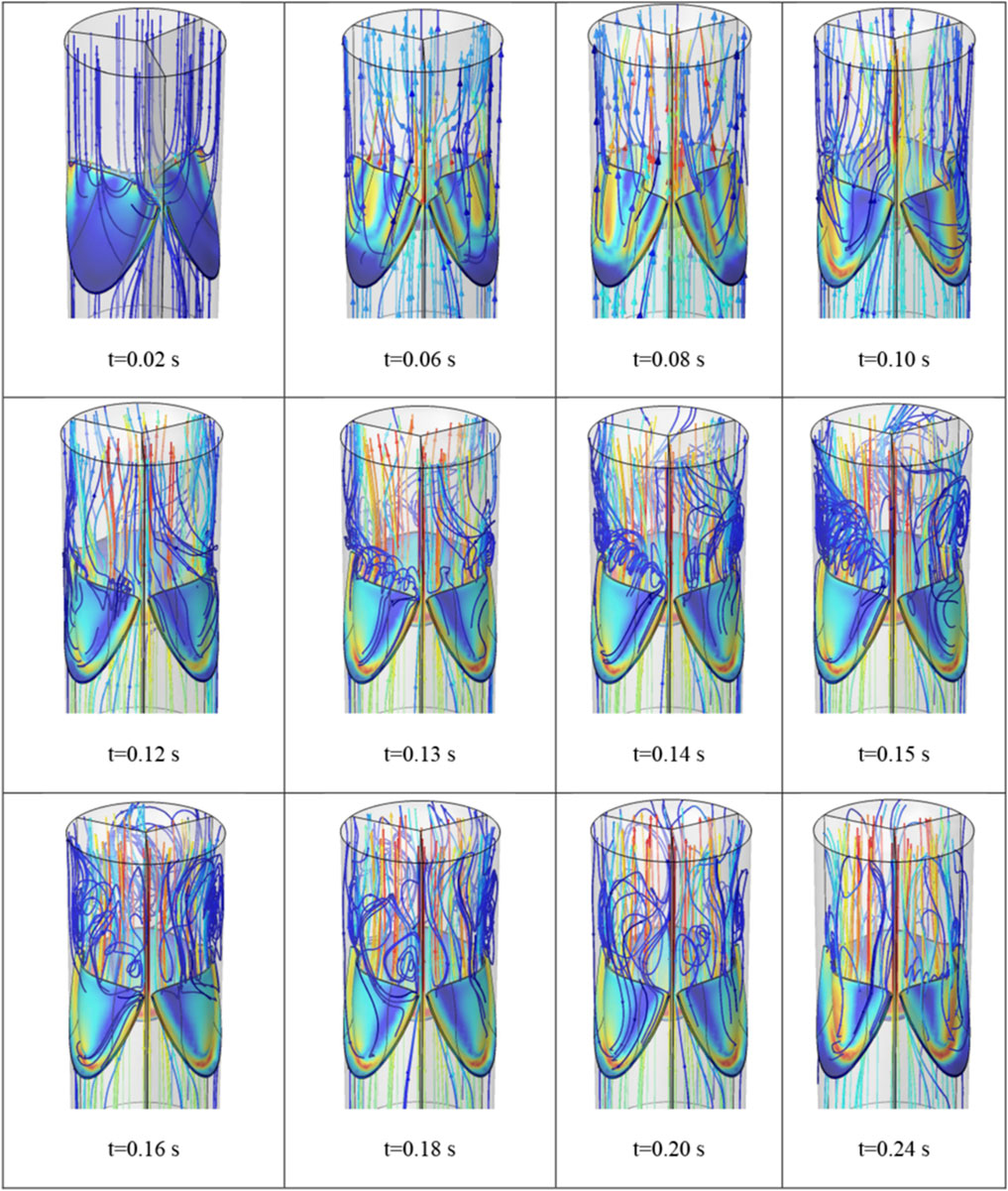
FIGURE 9. Streamlines of the blood flow during the valve opening.
Another important parameter of the performance of the prosthetic heart valves is the opening area percentage which is obtained as follows:
For the present design, the valve cross-section area at the largest opening is equal to 224.3 mm2, which is obtained using image-digitizing software. Since the vessel radius is 10 mm, the OA is obtained to be equal to 71%. This parameter is compared with the similar published studies in Table 3. It follows that the present design yields better results, compared with the similar studies. As we discussed earlier, the slope and curvature of the leaflets play a crucial role in the opening area of the valve.
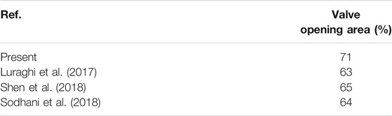
TABLE 3. Valve opening area percentage results.
Conclusion
Fluid-structure interaction simulations are promising for design cycle of the prosthetic heart valves because of the detained information that are obtained by them. From the mechanical point of view, a good prosthetic heart valve should have a large opening area to allow the blood flow to be as close to the natural valve as possible, while with as small stress as possible so that the operational life of the valve is as high as possible. To come up with the proper design, first, we conducted a series of 2D simulations to assess the effects of leaflet curvature on the performance of the valve. It is observed that the leaflets with linear profile and larger slope at the skirt area give the required features. Using this outcome, a 3D model is constructed and its geometrical parameters are varied so that the best possible performance parameters are obtained. The final design is simulated using fully coupled FSI analysis with results compared with the published data. It is shown that the present model gives better results for the valve opening area and the stress developed on the leaflets.
Data Availability Statement
The original contributions presented in the study are included in the article/supplementary material; further inquiries can be directed to the corresponding author.
Author Contributions
All authors listed have made a substantial, direct, and intellectual contribution to the work and approved it for publication.
Conflict of Interest
The authors declare that the research was conducted in the absence of any commercial or financial relationships that could be construed as a potential conflict of interest.
Publisher’s Note
All claims expressed in this article are solely those of the authors and do not necessarily represent those of their affiliated organizations or those of the publisher, the editors, and the reviewers. Any product that may be evaluated in this article, or claim that may be made by its manufacturer, is not guaranteed or endorsed by the publisher.
References
Abbas, S. S., Nasif, M. S., and Al-Waked, R. (2022). State-of-the-art Numerical Fluid–Structure Interaction Methods for Aortic and Mitral Heart Valves Simulations: A Review. SIMULATION 98, 3–34. doi:10.1177/00375497211023573
Arcidiacono, G., Corvi, A., and Severi, T. (2005). Functional Analysis of Bioprosthetic Heart Valves. J. Biomech. 38, 1483–1490. doi:10.1016/j.jbiomech.2004.07.007
Ataee, B., Khorasani, M. T., Karimi, M., and Daliri-Joupari, M. (2021). Surface Modification of Polyurethane/HCNT Nanocomposite with Octavinyl Polyhedral Oligomeric Silsesquioxane as a Heart Valve Material. Int. J. Polymeric Mater. Polymeric Biomater. 1–14. doi:10.1080/00914037.2021.1937160
Avanzini, A. (2017). Influence of Leaflet's Matrix Stiffness and Fiber Orientation on the Opening Dynamics of a Prosthetic Trileaflet Heart Valve. J. Mech. Med. Biol. 17, 1750096. doi:10.1142/s0219519417500968
Bailoor, S., Seo, J.-H., Dasi, L. P., Schena, S., and Mittal, R. (2021). A Computational Study of the Hemodynamics of Bioprosthetic Aortic Valves with Reduced Leaflet Motion. J. Biomech. 120, 110350. doi:10.1016/J.JBIOMECH.2021.110350
Black, M. M., Drury, P. J., and Tindale, W. B. (1983). Twenty-Five Years of Heart Valve Substitutes: A Review1. J. R. Soc. Med. 76, 667–680. doi:10.1177/014107688307600809
Borazjani, I. (2013). Fluid-structure Interaction, Immersed Boundary-Finite Element Method Simulations of Bio-Prosthetic Heart Valves. Comp. Methods Appl. Mech. Eng. 257, 103–116. doi:10.1016/J.CMA.2013.01.010
Driessen, N. J. B., Mol, A., Bouten, C. V. C., and Baaijens, F. P. T. (2007). Modeling the Mechanics of Tissue-Engineered Human Heart Valve Leaflets. J. Biomech. 40, 325–334. doi:10.1016/j.jbiomech.2006.01.009
Fallahiarezoudar, E., Ahmadipourroudposht, M., Idris, A., and Yusof, N. M. (2017). Optimization and Development of Maghemite (γ-Fe2O3) Filled Poly-L-Lactic Acid (PLLA)/thermoplastic Polyurethane (TPU) Electrospun Nanofibers Using Taguchi Orthogonal Array for Tissue Engineering Heart Valve. Mater. Sci. Eng. C 76, 616–627. doi:10.1016/J.MSEC.2017.03.120
Fallahiarezoudar, E., Ahmadipourroudposht, M., Yusof, N. M., Idris, A., and Ngadiman, N. H. A. (2017). 3D Biofabrication of Thermoplastic Polyurethane (TPU)/Poly-l-lactic Acid (PLLA) Electrospun Nanofibers Containing Maghemite (γ-Fe2O3) for Tissue Engineering Aortic Heart Valve. Polymers 9, 584. doi:10.3390/POLYM9110584
Gasparotti, E., Vignali, E., Losi, P., Scatto, M., Fanni, B. M., Soldani, G., et al. (2018). A 3D Printed Melt-Compounded Antibiotic Loaded Thermoplastic Polyurethane Heart Valve Ring Design: an Integrated Framework of Experimental Material Tests and Numerical Simulations. Int. J. Polymeric Mater. Polymeric Biomater. 68, 1–10. doi:10.1080/00914037.2018.1525717
Geronzi, L., Gasparotti, E., Capellini, K., Cella, U., Groth, C., Porziani, S., et al. (2021). High Fidelity Fluid-Structure Interaction by Radial Basis Functions Mesh Adaption of Moving walls: A Workflow Applied to an Aortic Valve. J. Comput. Sci. 51, 101327. doi:10.1016/J.JOCS.2021.101327
Gilmanov, A., and Sotiropoulos, F. (2015). Comparative Hemodynamics in an Aorta with Bicuspid and Trileaflet Valves. Theor. Comput. Fluid Dyn. 30, 67–85. doi:10.1007/S00162-015-0364-7
Gulbulak, U., Ertas, A., Baturalp, T. B., and Pavelka, T. (2020). The Effect of Fundamental Curves on Geometric Orifice and Coaptation Areas of Polymeric Heart Valves. J. Mech. Behav. Biomed. Mater. 112, 104039. doi:10.1016/J.JMBBM.2020.104039
Hsu, M.-C., Kamensky, D., Xu, F., Kiendl, J., Wang, C., Wu, M. C. H., et al. (2015). Dynamic and Fluid-Structure Interaction Simulations of Bioprosthetic Heart Valves Using Parametric Design with T-Splines and Fung-type Material Models. Comput. Mech. 55, 1211–1225. doi:10.1007/S00466-015-1166-X
Kazeroni, Z. S., Telloo, M., Farazin, A., Saber-Samandari, S., Sheikhbahaei, E., Kamyab-Moghadas, B., et al. (2021). A Mitral Heart Valve Prototype Using Sustainable Polyurethane Polymer: Fabricated by 3D Bioprinter, Tested by Molecular Dynamics Simulation. AUT J. Mech. Eng. 5, 109–120. doi:10.22060/AJME.2020.17450.5862
Kerr, M. M., and Gourlay, T. (2020). Design and Numerical Simulation for the Development of an Expandable Paediatric Heart Valve. Int. J. Artif. Organs 44, 518–524. doi:10.1177/0391398820977509
Kim, H., Lu, J., Sacks, M. S., and Chandran, K. B. (2007). Dynamic Simulation of Bioprosthetic Heart Valves Using a Stress Resultant Shell Model. Ann. Biomed. Eng. 36, 262–275. doi:10.1007/s10439-007-9409-4
Lee, J. H., Rygg, A. D., Kolahdouz, E. M., Rossi, S., Retta, S. M., Duraiswamy, N., et al. (2020). Fluid-Structure Interaction Models of Bioprosthetic Heart Valve Dynamics in an Experimental Pulse Duplicator. Ann. Biomed. Eng. 48, 1475–1490. doi:10.1007/S10439-020-02466-4
Liao, K., Seifter, E., Hoffman, D., Yellin, E. L., and Frater, R. W. M. (1992). Bovine Pericardium versus Porcine Aortic Valve: Comparison of Tissue Biological Properties as Prosthetic Valves. Artif. Organs 16, 361–365. doi:10.1111/J.1525-1594.1992.TB00532.X
Luraghi, G., Wu, W., de Gaetano, F., Rodriguez Matas, J. F., Moggridge, G. D., Serrani, M., et al. (2017). Evaluation of an Aortic Valve Prosthesis: Fluid-Structure Interaction or Structural Simulation. J. Biomech. 58, 45–51. doi:10.1016/j.jbiomech.2017.04.004
Meddahi-Pelle, A., Pavon-Djavid, G., Chakfe, N., and Heim, F. (2021). How Yarn Orientation Limits Fibrotic Tissue Ingrowth in a Woven Polyester Heart Valve Scaffold: a Case Report. Biomed. Eng./Biomedizinische Technik 66, 225–230. doi:10.1515/BMT-2020-0137
Mohmad Saberi, S. E. (2020). Development of 3D Printed Biodegradable Polyurethane Nanohybrid Scaffold for Heart Valve Regeneration. UCL: Doctoral Thesis.
Nestola, M. G. C., Zulian, P., Gaedke-Merzhäuser, L., and Krause, R. (2021). Fully Coupled Dynamic Simulations of Bioprosthetic Aortic Valves Based on an Embedded Strategy for Fluid-Structure Interaction with Contact. EP Europace 23, i96–i104. doi:10.1093/europace/euaa398
Park, M. H., Zhu, Y., Imbrie-Moore, A. M., Wang, H., Marin-Cuartas, M., Paulsen, M. J., et al. (2021). Heart Valve Biomechanics: The Frontiers of Modeling Modalities and the Expansive Capabilities of Ex Vivo Heart Simulation. Front. Cardiovasc. Med. 8, 689. doi:10.3389/fcvm.2021.673689
Shen, X., Bai, L., Cai, L., and Cao, X. (2018). A Geometric Model for the Human Pulmonary Valve in its Fully Open Case. PLoS One 13, e0199390. doi:10.1371/journal.pone.0199390
Siddiqui, R. F., Abraham, J. R., and Butany, J. (2009). Bioprosthetic Heart Valves: Modes of Failure. Histopathology 55, 135–144. doi:10.1111/J.1365-2559.2008.03190.X
Sodhani, D., Reese, S., Aksenov, A., Soğanci, S., Jockenhövel, S., Mela, P., et al. (2018). Fluid-structure Interaction Simulation of Artificial Textile Reinforced Aortic Heart Valve: Validation with an In-Vitro Test. J. Biomech. 78, 52–69. doi:10.1016/j.jbiomech.2018.07.018
Thomas, V., and Jayabalan, M. (2008). A New Generation of High Flex Life Polyurethane Urea for Polymer Heart Valve-Studies Onin Vivo Biocompatibility and Biodurability. J. Biomed. Mater. Res. 89A, 192–205. doi:10.1002/JBM.A.31937
Vaesken, A., Heim, F., and Chakfe, N. (2014). Fiber Heart Valve Prosthesis: Influence of the Fabric Construction Parameters on the Valve Fatigue Performances. J. Mech. Behav. Biomed. Mater. 40, 69–74. doi:10.1016/J.JMBBM.2014.08.015
Zakaria, M. S., Ismail, F., Tamagawa, M., Aziz, A. F. A., Wiriadidjaja, S., Basri, A. A., et al. (2017). Review of Numerical Methods for Simulation of Mechanical Heart Valves and the Potential for Blood Clotting. Med. Biol. Eng. Comput. 55, 1519–1548. doi:10.1007/S11517-017-1688-9
Zhou, H., Wu, L., and Wu, Q. (2021). Structural Stability of Novel Composite Heart Valve Prostheses - Fatigue and Wear Performance. Biomed. Pharmacother. 136, 111288. doi:10.1016/J.BIOPHA.2021.111288
Keywords: prosthetic heart valve, polymeric heart valve, fluid–structure interaction, finite element simulation, valve opening
Citation: Ghanbari J, Dehparvar A and Zakeri A (2022) Design and Analysis of Prosthetic Heart Valves and Assessing the Effects of Leaflet Design on the Mechanical Attributes of the Valves. Front. Mech. Eng 8:764034. doi: 10.3389/fmech.2022.764034
Received: 24 August 2021; Accepted: 11 January 2022;
Published: 04 February 2022.
Edited by:
Omid Bavi, Shiraz University of Technology, IranReviewed by:
Reza Roohi, Fasa University, IrelandMaria Giuseppina Chiara Nestola, University of Italian Switzerland, Switzerland
Copyright © 2022 Ghanbari, Dehparvar and Zakeri. This is an open-access article distributed under the terms of the Creative Commons Attribution License (CC BY). The use, distribution or reproduction in other forums is permitted, provided the original author(s) and the copyright owner(s) are credited and that the original publication in this journal is cited, in accordance with accepted academic practice. No use, distribution or reproduction is permitted which does not comply with these terms.
*Correspondence: Jaafar Ghanbari, ghanbari@qut.ac.ir