Design and development of a peristaltic pump for constant flow applications
 Patrich Ferretti
  Curzio Pagliari
 Andrea Montalti
- Department of Industrial Engineering, Alma Mater Studiorum University of Bologna, Bologna, Italy
In wide-ranging areas, including hydraulics, biomedical, automotive, and aerospace, there is often a need to move a fluid with a constant flow rate. This is difficult to achieve with any type of pump and usually other elements are inserted to regularize the output. This study focused on the peristaltic pump because there are few studies on it and it has some interesting features, such as extreme simplicity, a small number of components, and the extreme compactness of the whole system. The first part of this study is focused on analyzing the classical geometry of the peristaltic pump to understand the origin of the discontinuity in the flow rate; the second part proposes a new geometry that mitigates the flow irregularity by more than 200%. In this way, it is possible to use it in all the sectors where a constant flow rate is required but where insulation between the fluid and the machine is required. Together with the flow study, an analysis of how the main geometric parameters affect the operation of the pump is provided, complete with explanatory graphs and tables. A prototype made through additive manufacturing technologies is also proposed.
1 Introduction to the peristaltic pump
The peristaltic pump applies the principle of peristalsis (Jaffrin and Shapiro, 1971; Turton, 1994), whereby the prevalence of the treated fluid is imposed by a restriction running along the pipe (Weinberg et al., 1971; El-Din and Rabi, 2009). The pump consists of a rotor to which two or more rollers are attached, which rotate to throttle the pipe against the case isolating a volume of fluid and transferring it from the suction to the discharge (Latham, 1966; Shapiro et al., 1969; Karassik et al., 2008). Depending on the type of fluid, the element that chokes the pipe changes. For fluids with solid elements in suspension, skids are used while for fluids without solid particles, rollers are utilized (Saunier et al., 2022).
These pumps are widely used in all the processes where there is a requirement that the fluid should not meet machine components (Volk, 2013), for example, in the medical (Kunz et al., 1997; Khandpur, 2003), chemical (Farooq and Hussain, 2022), pharmaceutical (Abd-Alla et al., 2022a), or food industries (Liu et al., 2018). The dimensions vary according to the application (Formato et al., 2018), the nominal flow rate, and the type of fluid to be handled; they vary from tubes with an internal diameter of 2 mm for low-density fluids with no suspended particles, to tubes of 130 mm for high flow rates and transport of fluids with suspended bodies (Chakraborty et al., 2012). The number of rollers in commercially available pumps is usually 2 or 3. Small pumps are made with plastic components because they are lighter and cheaper, also they have to withstand a smaller number of operating hours; large pumps are made of metal materials to ensure good structural strength, proper operation given the forces involved, and a high number of operating hours (Elabbasi et al., 2011).
This article starts with the study of the classic peristaltic pump (Sausse, 2018) to study the pulsation generated by the fluid flow. It is one of the few pumps that allow the fluid to be isolated from the moving parts of the pump but in many sectors, they are forced to use other types because this behavior of the fluid is not permissible. Unlike other works in the literature (Abd-Alla et al., 2021; Bayones et al., 2021; Abd-Alla et al., 2022b; Bayones et al., 2022; Abd-Alla et al., 2022c; Abd-Alla A. M. et al., 2022; Abd-Alla et al., 2023a; Abd-Alla et al., 2023b) regarding the geometry of the machine (Kaplan et al., 2018), it was possible to obtain a constant flow rate (Formato et al., 2019) without losing performance and finally, a prototype was created using 3D printing technology (Dave and Davim, 2021; Hsu et al., 2022).
1.1 Introduction to FDM for the realization of functional parts
FDM is the most renowned 3D printing method in the market (Kristiawan et al., 2021) due to the variety of possible printable materials from mainstream PLA (Arockiam et al., 2022) to more professional materials such as nylons, reinforced polymers (Wickramasinghe et al., 2020) such as carbon fiber and ABS, and up to engineering materials such as Polyether ether ketone (PEEK) (Wang et al., 2020) and Polypropylene (PP) (Bachhar et al., 2020). 3D printing has been known for its ability in creating complex geometries at low costs, especially for rapid prototyping applications (Kafle et al., 2021). Nevertheless, FDM methodologies are still challenging as their exterior surface quality and internal structure (Kumar et al., 2022) makes these products difficult to be standardized for mechanical applications (Wickramasinghe et al., 2020). Moreover, because of the technology, they result in low productivity (Raza et al., 2022) while they prove to be solid for low-cost end-use parts and small-lot production (Rouf et al., 2022). FDM printing processes have many fields of applications: biomedical (Frizziero et al., 2022a), tissue engineering, human bone repair (Alessandri et al., 2022; Alessandri et al., 2023), antibacterial, bioprinting (Chaturvedi et al., 2022), electrical conductivity (Mora et al., 2020), electromagnetic, sensor, battery, automotive (Romero et al., 2021; Frizziero et al., 2022b; Frizziero et al., 2022c; Frizziero et al., 2023), aviation, smart textile (Chakraborty and Biswas, 2020), environmental, and luminescence applications among other areas (Jandyal et al., 2022).
1.2 Objectives
In summary, the objectives of the work are.
• find a geometry that allows a constant flow rate to be obtained;
• analyze how the flow varies as the geometric parameters of the pump vary;
• create a simple geometry composed of a few components.
2 Materials and methods
2.1 Displacement and flow rate of the classical peristaltic pump
A parameterization using geometric data that can be shared among various models of peristaltic pumps is presented and formulas and schematizations for calculating displacement and flow rate are then illustrated.
The peristaltic pump consists of a rotor to which two or more rollers are attached that rotate, squeezing the tube against the case, isolating a volume of fluid, and moving it from the suction to the discharge (Figure 1). Two zones of the machine are defined, the first is the “transfer zone” where the fluid is isolated and moved from the suction to the discharge and is 180° wide; the second is the “disengagement zone,” consecutive to the first and defines the amplitude in which the roller moves away from the tube until it makes no contact.
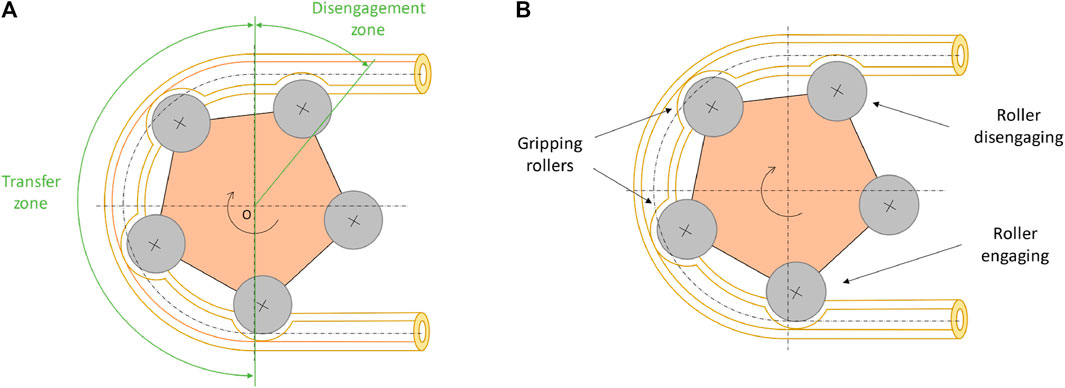
FIGURE 1. Schematics of the peristaltic pump (A) Functional zones of the machine; (B) Description of the rollers in the stages of rotor rotation.
Beginning with the calculation of the displacement, considering the internal volume of the tube running through the entire transfer zone, which will have to be multiplied by two to consider a full rotation of the rotor.
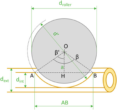
FIGURE 2. Diagram of machine and detail of a roller engaged on the tube.
Using the two relationships, the internal volume of the tube (
The volume occupied by the z rollers crushing the tube should be subtracted (
The volume occupied by the roller crushing the pipe, considering the pipe locally straight, is obtained from the intersection between two cylinders with different diameters at skewed axes. A schematization is presented in Figure 3.
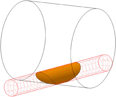
FIGURE 3. The volume given by the intersection of two cylinders with different diameters at skewed axes.
To derive the volume of the fluid element, begin by calculating the area of the circular segment when the roller crushes the tube; this is done theoretically by considering a tube that adheres perfectly to the roller as depicted in the figure below.
Knowing that:
Considering Figure 4, the Pythagorean theorem is applied to derive the segment AH:
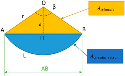
FIGURE 4. Diagram of the circular sector with construction parameters.
From which it is possible to derive the segment AB:
Carnot’s theorem on the AOH triangle:
From which the angle β′ is derived:
Turning then to the ß angle:
With a simple proportion, the length of the arc of the circumference of the circular sector is calculated:
Knowing that the area of the circular sector (yellow area + blue area in Figure 4) and the area of the triangle (yellow area in Figure 4) are:
The area of the circular segment is easily derived:
To obtain the volume of the circular segment, one must multiply the area found by its depth, in this case, it is the inner diameter of the pipe. Mathematically, a solid is generated that has a rectangular cross-section along the longitudinal axis represented in Figure 5 on the left. The theoretical volume to be calculated is represented in Figure 5 on the right.
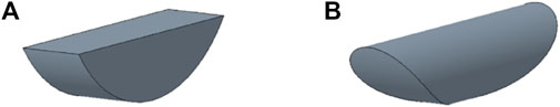
FIGURE 5. (A) Shape of the calculated volume; (B) Shape of the theoretical volume.
To arrive at an approximate solution of the volume sought, a corrective term is inserted into the element volume formula, which is the ratio of the area of the circle to the area of the square circumscribed by the circle.
Through this procedure, the calculated volume differs by approximately 2% from the theoretical volume calculated through the CAD program.
For the exact calculation, one would have to perform a triple integral on the intersection volume of two cylinders with skewed axes and different diameters (similar to Steinmetz volume), it presents too much complexity for the intended purpose.
The volume of the circular segment will be:
In conclusion, the displacement of the machine will be:
Knowing the rated capacity and displacement of the machine, it is possible to derive the rotational speed of the motor to properly move the pump.
The flow rate has been made independent of the pump rotation speed, so all considerations and comparisons will be comparable without having to define a rotation speed.
To define the flow rate in this machine geometry, the volume of fluid moved with a rotation of one degree by the last fully engaged roller in the conveying zone is estimated, from which the change in volume due to the roller disengaging on the pipe must be subtracted.
As can be seen in Figure 6, the angle ε defines the angular position of the rotor; deriving the angle γ knowing that the sum of the interior angles of a triangle (AOB) always makes 180:
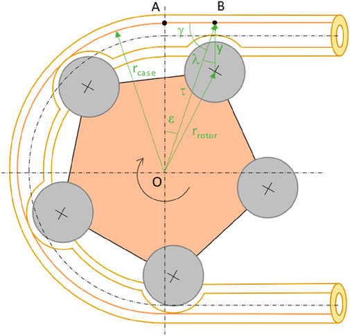
FIGURE 6. Schematic diagram of the pump with construction parameters.
Knowing the AO side and the two angles ε and γ, the OB side called τ can be derived:
Knowing the radius of the rotor, the cosine theorem is applied:
To derive the parameter y that varies as the angle ε changes:
One must choose the negative sign otherwise it makes no physical sense.
Considering Figure 7, the distance y is used to obtain the parameter f, which is of interest until the roller completely disengages from the tube, and is obtained through the closure equation:
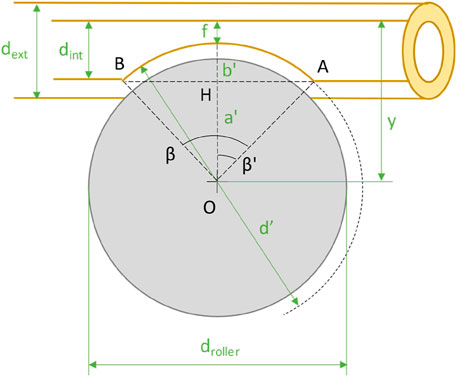
FIGURE 7. Detail of the roller being gripped on the tube with construction parameters.
Needed to derive the parameter a’, which at the point of last detachment will be equal to the radius of the roller:
Once the parameter aʹ is obtained, one can proceed with the calculation of the volume occupied by the roller on the tube, as carried out for the calculation of the displacement. Starting from Eq. (8), AH (Figure 7) is obtained, to obtain ß and arrive at the surface area value of the circular segment. The calculation of the volume of the fluid element is carried out as in Eq. (18). Plotting the trend on a graph, the curve shown in Figure 8 is obtained.
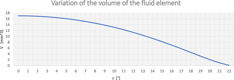
FIGURE 8. Variation of fluid element volume as angle ε changes during roller disengagement.
Knowing the volume occupied by the roller as the angle ε changes, the change in volume between one position (ε) and the next (ε + 1) is calculated:
Finally, the change in volume of the liquid with one degree rotation is calculated:
Considering:
The flow rate of this pump has two phases.
- The first phase begins when the roller has finished the transfer arc and no longer completely occludes the pipe, generating a passage light for the fluid. From this moment, the roller disengagement phase begins and ends when there is no more contact between the roller and the pipe. The duration of this phase is approximately 22.
- The second phase begins at the end of the first one and is the remaining rotation that transfers fluid to the delivery with a constant trend until the next roller begins to disengage from the pipe.
The entire cycle repeats every 360/z, where z = 5, so every 72.
Putting this concept back into formulas, getting:
The results of the described relationships are represented on a graph in Figure 9.
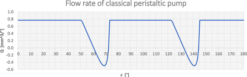
FIGURE 9. Flow rate of the peristaltic pump with classical geometry.
Some performance indicators are defined so that results can be evaluated and compared with each other:
Irregularity:
Average flow rate:
Average percentual flow rate:
From Figure 9, it can be seen that the flow irregularity is due to the disengagement of the roller from the pipe; in particular, there are some instances when the amount of fluid moved toward the discharge is less than the volume change due to the disengagement, resulting in a negative flow rate, i.e., fluid return.
This trend is caused by the disengagement of the roller in an arc of a very short length (≈22°). Such behavior is not permissible.
By varying construction parameters such as roller diameter, tube diameter, number of rollers, and rotor diameter, it is possible to limit the amplitude of negative peaks by obtaining a reasonable irregularity and a good average flow rate.
Unfortunately, none of the parameters allow for a constant flow rate or one that can be considered as such, the problem being due to the abrupt disengagement of the roller that generates a major oscillation in the flow rate.
2.2 Displacement and flow rate of eccentric peristaltic pump
The concept behind the new geometry is to increase the disengagement zone to reduce the flow irregularity (Figure 10).
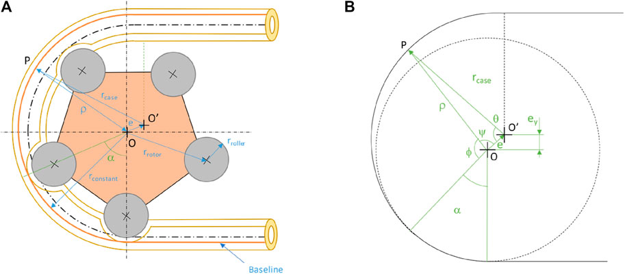
FIGURE 10. (A) Machine diagram with construction parameters; (B) Conceptual diagram with construction parameters.
The new geometry consists of a first zone, called the “transfer zone,” with a constant radius of amplitude equal to the angle between two successive rollers (e.g., 5-roller rotor, so α = 360/z = 72), which is necessary to isolate the fluid element and prevent the connection between discharge and suction.
The second zone, called the “disengagement zone,” has an eccentric arc to disengage the roller gradually, reducing the irregularity in the flow rate.
A working arc of 180 was also predetermined for this pump geometry so as to have comparable results. From the analyses below it will be clear whether this geometry really brings advantages over the classical pump.
As can be seen in Figure 10, angle α defines the arc of the case with a constant radius centered in O, and angle θ defines the arc of the case with eccentric geometry with the center in O':
Defining a generic point of contact P yields the triangle OPO’ and applying Carnot’s theorem gives:
The positive sign must be chosen otherwise it makes no physical sense.
The parameter ρ defines the diameter of the case according to the value of θ and the other geometric parameters. The graphical representation is shown in Figure 11.
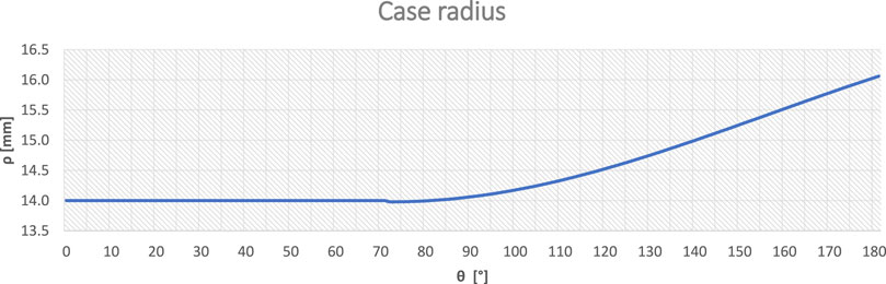
FIGURE 11. Case curvature radius ρ as a function of angle θ.
In the triangle OPO,’ while knowing the angle θ which is referred to O′, one can derive the angle φ because it is refers to O and then derive ψ:
And finally, getting φ:
As a verification, Carnot’s theorem can be reapplied by referring to the angle φ instead of θ:
The positive sign must be chosen otherwise it makes no physical sense.
To derive the volume of fluid occupied by the roller in all stages of disengagement, as can be seen in Figure 12, it is necessary to know the parameter x:
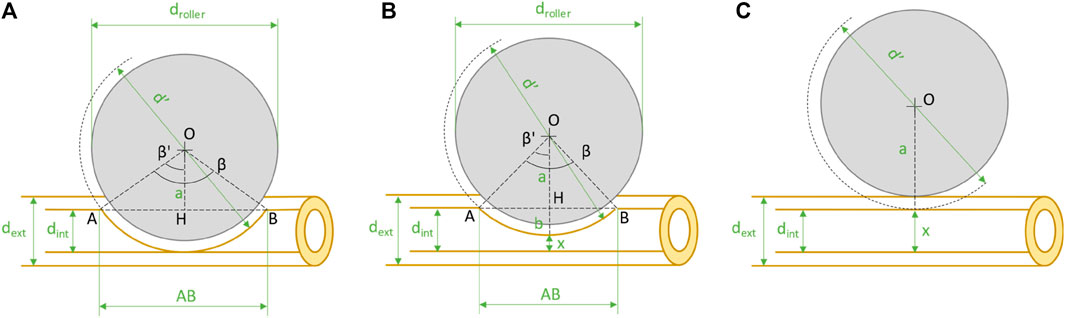
FIGURE 12. Schematic diagram of roller disengagement from the pipe with the geometrical parameters in the three stages: (A) Initial situation before disengagement (ε = 0 ÷ α); (B) Intermediate situation during disengagement (ε = α ÷ 180-α); (C) Final situation when disengagement is finished (ε = 180).
Deriving the b term and finally the a term:
At this point, we will refer to the calculations made earlier for the classical peristaltic pump in Eq. (8).
Knowing the volume occupied by the rollers in both the constant-radius phase and the variable-radius phase, it is possible to derive the displacement, which is approximately 11% greater than in the classical pump.
With the new case geometry, the flow rate will be calculated as before, except that the number of rollers that disengage, in some phases, will be more than one at a time (Figure 13).
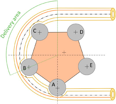
FIGURE 13. Diagram of roller disengagement in the rotor rotation stages.
For clarity, the formulas previously described are given:
The change in volume due to the gripping rollers varies depending on the angle of the rotor considered.
In this machine geometry, the transfer zone is reduced to the essentials to ensure no communication between suction and delivery and to maximize the roller disengagement zone from the pipe. Representing the instantaneous flow rate values on a graph yields the following (Figure 14).
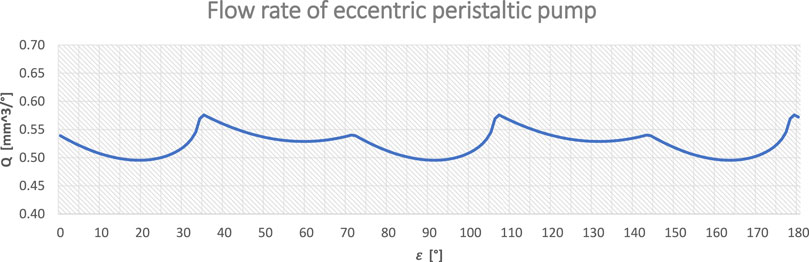
FIGURE 14. Flow rate of the eccentric peristaltic pump.
The flow rate trend is periodic, with a period defined by the angle between two rollers, which in this case is 72.
3 Results
By comparing the flow rate curves of the two types of pumps, a marked improvement in the pump’s flow rate is observed with a drastic reduction in irregularity; by varying some geometric parameters, its operation can be further improved.
In the following, the flow rate as structural parameters of the pump are adjusted will be analyzed by taking advantage of the representation on graphs (Figure 15) and the indices of irregularity, average flow rate, and average flow rate percentage. Only one parameter will be adjusted at a time to better appreciate its influence.
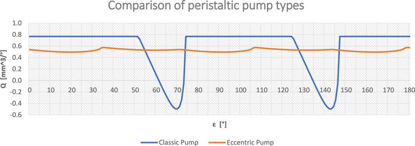
FIGURE 15. Flow rate comparison between classical and eccentric pump.
3.1 Geometric parameters of the eccentric pump
3.1.1 Variation of roller diameter
It can be seen from the graph (Figure 16) that as the roller diameter increases, there is a downward shift in the curve, leading to a reduction in the average flow rate. Since a large roller engaging on the pipe occupies a larger volume of fluid there is a reduction in displacement and flow rate.
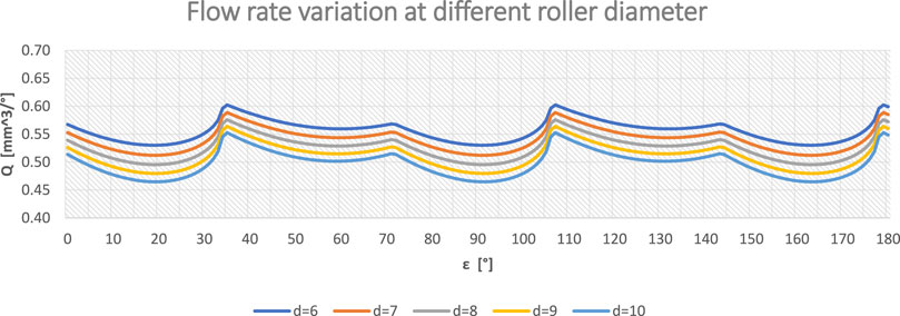
FIGURE 16. Flow rate at varying roller diameter.
Analyzing the indices of the five curves shows that as the diameter of the rollers increases, there is a slight increase in irregularity. Information that cannot be appreciated from the graph is shown in Table 1.
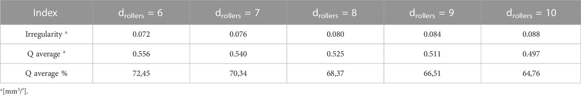
TABLE 1. Indices as roller diameter changes.
3.1.2 Variation in the number of rollers
There is a significant reduction in irregularity as the number of rollers increases and considering that each roller is a pumping element because it isolates an element of fluid to carry it to the discharge, the rule that a pump with ‘pumping elements’ of an odd number has less irregularity than one with a higher number of pumping elements internally is verified (Figure 17).
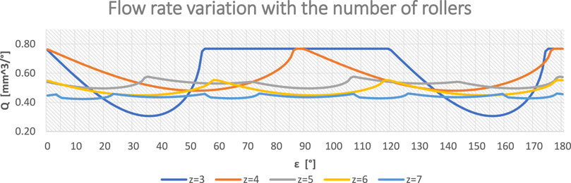
FIGURE 17. As z (the number of rollers) increases, the average flow rate is slightly reduced and the pulsation frequency increases but its amplitude is reduced, making the flow more constant.
By increasing z, the angle of the transfer zone drops, making the disengagement zone more gradual, thus achieving a reduction in the irregularity of the flow rate (Table 2).
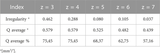
TABLE 2. Indices as the number of rollers changes.
This also results in a reduction in the average flow rate caused by increasing the fluid volume occupied by the rollers gripping the pipe.
Below are diagrams of machines with different numbers of rollers (Figure 18).
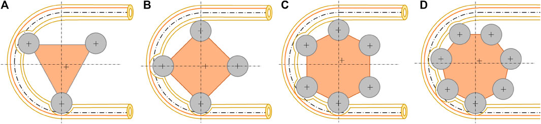
FIGURE 18. Diagrams of machine geometries with different numbers of rollers: (A) 3 rollers; (B) 4 rollers; (C) 6 rollers; (D) 7 rollers.
A bearing number of less than 3 was not considered because it does not allow the use of this eccentric geometry and we avoided going beyond z = 7 because it would require a larger rotor size and was not justifiable for the reduced improvement in irregularity.
3.1.3 Variation of tube diameter
Increasing the inner diameter of the pipe brings a quadratic increase in the flow rate but with a consequent increase in the irregularity. This is because the volume of fluid occupied by the roller, in a large pipe, is larger than in a small pipe.
For simplicity, the pipe thickness was kept constant in the five cases (Figure 19). In Table 3 the variation of the main indices is summarized.
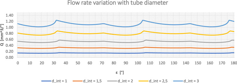
FIGURE 19. Flow rate as the inner diameter of the tube changes.
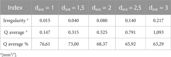
TABLE 3. Indices as the inner diameter of the tube changes.
3.1.4 Variation of case and rotor radius
As the rotor radius increases, there is a linear increase in the average flow rate and an almost constant irregularity (Figure 20). This is a useful parameter for increasing the average flow rate of the pump without having to give up good irregularity (Table 4). This is because a rotation of one degree of the rotor in a small case displaces less fluid than in a larger case with the same inner diameter of the tube and bearings. As the size of the rotor varies, the size of the case also varies consistently.
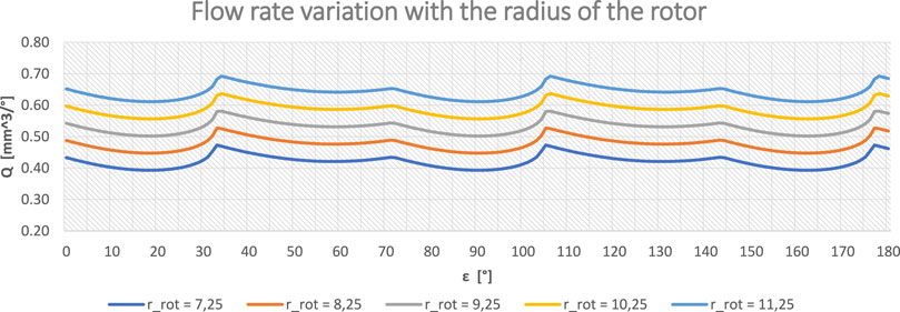
FIGURE 20. Flow rate as the radius of the rotor changes.
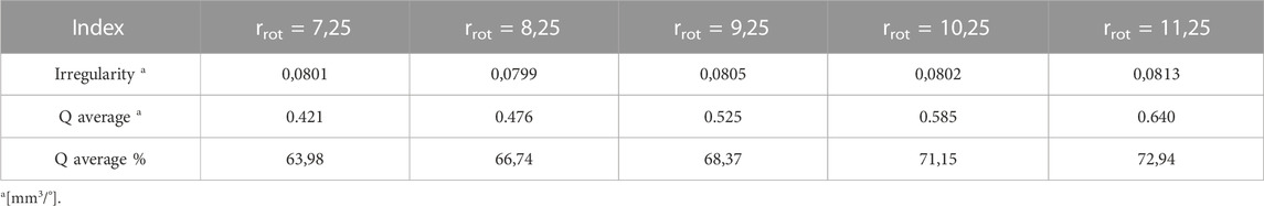
TABLE 4. Indices as rotor radius changes.
3.2 Realization of the 3D printed prototype
The peristaltic pump is one of the few pumps that can be made with 3D printing because there are no creeping elements that have to make a seal and need tight tolerances, it has few components and has no parts with complex geometries. Moreover, having the liquid inside the tube allows it to transport a fluid that is not akin to the material the pump is made of. Using CAD software, the eccentric pump was made (Figure 21) where all possible components were 3D printed, so the actual operation described and analyzed above could be verified. Given the small size of the prototype made, steel pins were used for the bearings; for larger machines, they could be printed in one piece with one of the two rotor flanges. Fixed wedges could be used as an alternative to rolling rollers; this configuration must provide for excellent lubrication to avoid excessive tube wear and reduced torque from the motor moving the pump.
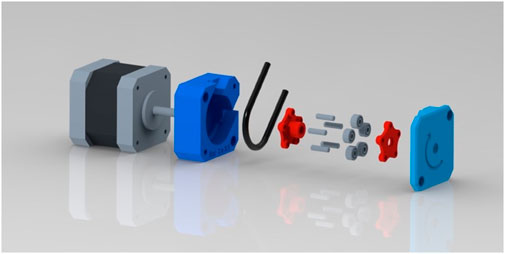
FIGURE 21. Exploded view representation of the pump.
Polyethylene terephthalate glycol (PETG), a material with fair mechanical properties in the range of 3D printing materials, was chosen, which has the following characteristics (Table 5).
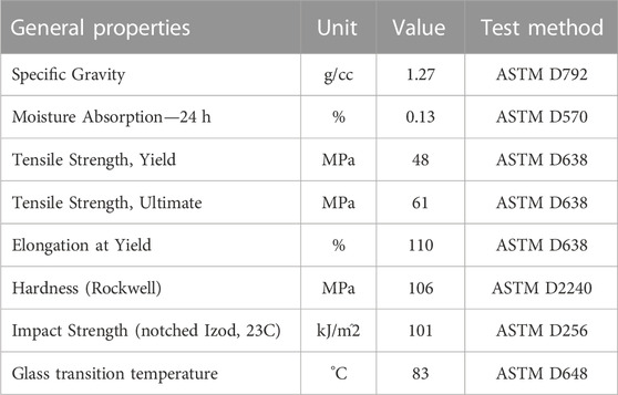
TABLE 5. General properties of PETG.
The design of the machine was structured to minimize supports and facilitate printing while minimizing the components to be assembled. The case is made of one piece and attached to the motor by two diametrically opposed screws, the rotor is composed of two flanges that support the pins and rollers that will be housed on the motor shaft via a form fit. Finally, there is the case closure flange, which prevents the tube from slipping out during operation, and is attached by two screws directly to the motor shell. The printing parameters used are as follows (Table 6).
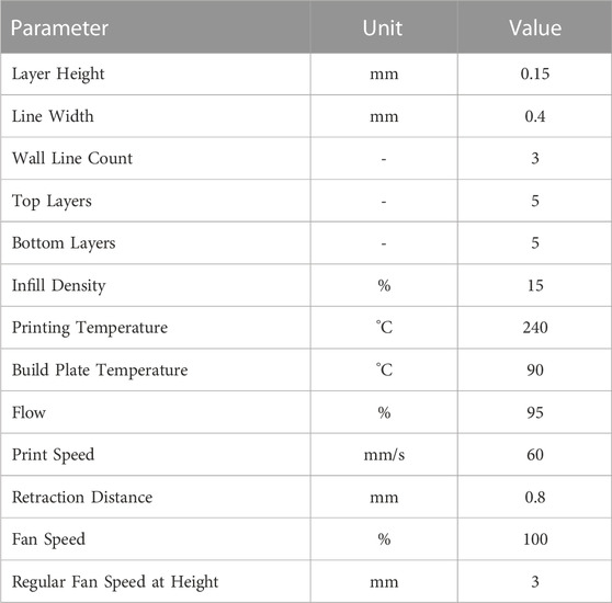
TABLE 6. Printing parameters.
The final 3D printed result is shown in Figure 22.
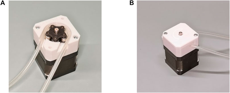
FIGURE 22. Photo of prototype made by 3D printing: (A) Without top flange with rotor and tube in view; (B) With top flange, ready for use.
4 Discussion
As a result of the illustrated analyses, the eccentric geometry of the machine greatly improved its operation. There was constant flow in the branch connected to the roller disengagement zone and the direction of rotation of the pump defined whether it was suction or delivery.
As needed, the same principle can be exploited to achieve both constant suction and delivery of the pump by inserting a part of the eccentric case before and after the constant radius transfer phase, but it is necessary to increase the working arc beyond 180°.
In summary, to further regularize the flow rate of the eccentric pump, one can.
- Reduce the diameter of the bearings;
- Increase the number of rollers;
- Reduce the diameter of the tube;
- Increase the disengagement arc of the rollers.
Table 7 shows the indices referring to the pump types, including two entries for the eccentric pump: the “standard” one uses generic parameters for good operation and the “plus” one maximizes the parameters to achieve very little irregularity.
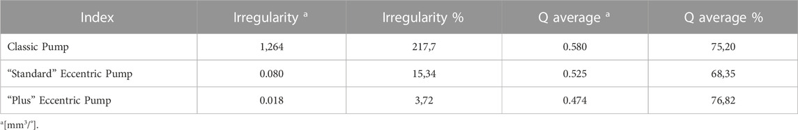
TABLE 7. Comparison of indices between pump types.
As can be seen from the values in the table, the “standard” eccentric pump has a flow rate with approximately 15 times less irregularity than the classic pump even though there is a slight decrease in the average flow rate.
The “plus” pump allows for a percentage flow rate irregularity of under 5% with a higher average percentage flow rate than the previous geometries. This means that of all the liquid that could flow in the pipe without roller-related obstructions, more than 75% arrives at the discharge; this can be used as a machine efficiency term. A graph (Figure 23) of the three pump types is also given for completeness.
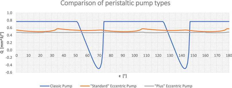
FIGURE 23. Comparison of flow rates among pump types.
Comparing the two pumps analyzed previously, and observing the percentage flow rate data, it can be seen that, at the same number of revolutions, the classic pump places approximately 7% more fluid at the delivery than the eccentric one. As a first approximation, the power losses of the two pumps can be considered equal because the materials, parameters, and boundary conditions are the same. It can be said that the classic pump requires less energy than the eccentric pump with the same flow rate delivered but does not allow obtaining a constant outgoing flow.
5 Conclusion
After carrying out various analyses and illustrating the results obtained, it emerged that the inclusion of an eccentricity in the pump body can lead to a considerable improvement in the reduction of the flow rate variability. This means that there is a better chance of using the pump efficiently. The geometry of the pump was parameterized to evaluate the effect on the flow rate by varying the main parameters. This made it easy to understand which modifications would be beneficial for a specific application. For example, reducing the diameter of the pipe can help reduce pulsations in the flow rate, even if this results in a decrease in the average pump flow rate. The pulsation in the flow rate of the classic pump has an irregularity greater than 200%, which leads to various problems within any circuit. With the new eccentric geometry, it is possible to reduce the irregularity by approximately 20 times.
The simple construction and the reduced number of components make the production and maintenance of the pump easy, guaranteeing excellent performance. Furthermore, this opens the door to various industries such as the biomedical, chemical, pharmaceutical, automotive, and aerospace industries. To demonstrate the ease of implementation and geometric feasibility of this type of pump, a working prototype was built using 3D printing technology.
Data availability statement
The original contributions presented in the study are included in the article/supplementary material, further inquiries can be directed to the corresponding author.
Author contributions
Conceptualization, AM; methodology, PF; software, AM; validation, AM; formal analysis, CP; investigation, AM; resources, AM; data curation, CP; writing—original draft preparation, AM; writing—review and editing, AM and PF; visualization, AM; supervision, AM and PF; project administration, AL and PF; funding acquisition, AL. All authors contributed to the article and approved the submitted version.
Conflict of interest
The authors declare that the research was conducted in the absence of any commercial or financial relationships that could be construed as a potential conflict of interest.
Publisher’s note
All claims expressed in this article are solely those of the authors and do not necessarily represent those of their affiliated organizations, or those of the publisher, the editors and the reviewers. Any product that may be evaluated in this article, or claim that may be made by its manufacturer, is not guaranteed or endorsed by the publisher.
References
Abd-Alla, A. M., Abo-Dahab, S. M., Abdelhafez, M. A., and Thabet, E. N. (2021). Effects of heat transfer and the endoscope on Jeffrey fluid peristaltic flow in tubes. Multidiscip. Model. Mater. Struct. 17 (5), 895–914. doi:10.1108/MMMS-12-2020-0292
Abd-Alla, A. M., Abo-Dahab, S. M., Thabet, E. N., and Abdelhafez, M. A. (2022b). Heat and mass transfer for MHD peristaltic flow in a micropolar nanofluid: Mathematical model with thermophysical features. Sci. Rep. 12, 21540. doi:10.1038/s41598-022-26057-6
Abd-Alla, A. M., Abo-Dahab, S. M., Thabet, E. N., Bayones, F. S., and Abdelhafez, M. A. (2023a). Heat and mass transfer in a peristaltic rotating frame Jeffrey fluid via porous medium with chemical reaction and wall properties. Alexandria Eng. J. 66, 405–420. doi:10.1016/j.aej.2022.11.016
Abd-Alla, A. M., Thabet, E. N., Bayones, F. S., and Alsharif, A. M. (2023b). Heat transfer in a non-uniform channel on MHD peristaltic flow of a fractional Jeffrey model via porous medium. Indian J. Phys. 97, 1799–1809. doi:10.1007/s12648-022-02554-2
Abd-Alla, A. M., Thabet, E. N., and Bayones, F. S. (2022c). Numerical solution for MHD peristaltic transport in an inclined nanofluid symmetric channel with porous medium. Sci. Rep. 12, 3348. doi:10.1038/s41598-022-07193-5
Alessandri, G., Frizziero, L., Santi, G. M., Liverani, A., Dallari, D., Vivarelli, L., et al. (2022). Virtual surgical planning, 3D-printing and customized bone allograft for acute correction of severe genu varum in children. J. Pers. Med. 12, 2051. doi:10.3390/JPM12122051
Abd-Alla, A. M., Abo-Dahab, S. M., Thabet, E. N., and Abdelhafez, M. A. (2022d). Impact of inclined magnetic field on peristaltic flow of blood fluid in an inclined asymmetric channel in the presence of heat and mass transfer. United Kingdom: Waves in Random and Complex Media. doi:10.1080/17455030.2022.2084653
Abd-Alla, A. M., Abo-Dahab, S. M., Thabet, E. N., and Abdelhafez, M. A. (2022a). Peristaltic pump with heat and mass transfer of a fractional second grade fluid through porous medium inside a tube, Sci. Rep. 12 10608–10614. doi:10.1038/s41598-022-14773-y
Arockiam, A. J., Subramanian, K., Padmanabhan, R. G., Selvaraj, R., Bagal, D. K., and Rajesh, S. (2022). A review on PLA with different fillers used as a filament in 3D printing. Mater. Today Proc. 50, 2057–2064. doi:10.1016/J.MATPR.2021.09.413
Bachhar, N., Gudadhe, A., Kumar, A., Andrade, P., and Kumaraswamy, G. (2020). 3D printing of semicrystalline polypropylene: Towards eliminating warpage of printed objects. Bull. Mater. Sci. 43, 171. doi:10.1007/s12034-020-02097-4
Bayones, F. S., Abd-Alla, A. M., and Thabet, E. N. (2022). Magnetized dissipative Soret effect on nonlinear radiative Maxwell nanofluid flow with porosity, chemical reaction and Joule heating. United Kingdom: Waves in Random and Complex Media. doi:10.1080/17455030.2021.2019352
Bayones, F. S., Abd-Alla, A. M., and Thabet, Esraa N. (2021). Effect of heat and mass transfer and magnetic field on peristaltic flow of a fractional maxwell fluid in a tube. Complexity 2021, 1–12. doi:10.1155/2021/9911820
Chakraborty, D., Prakash, J. R., Friend, J., and Yeo, L. (2012). Fluid-structure interaction in deformable microchannels. Phys. Fluids. 24, 102002. doi:10.1063/1.4759493
Chakraborty, S., and Biswas, M. C. (2020). 3D printing technology of polymer-fiber composites in textile and fashion industry: A potential roadmap of concept to consumer. Compos. Struct. 248, 112562. doi:10.1016/J.COMPSTRUCT.2020.112562
Chaturvedi, I., Jandyal, A., Wazir, I., Raina, A., and Ul Haq, M. I. (2022). Biomimetics and 3D printing - opportunities for design applications. Sensors Int. 3, 100191. doi:10.1016/j.sintl.2022.100191
Dave, H. K., and Davim, J. P. (2021). Fused deposition modeling based 3D printing. Berlin, Germany: Springer.
El-Din, M. G., and Rabi, M. (2009). Fluid power engineering. New York, NY, USA: McGraw-Hill Education.
Farooq, N., and Hussain, A. (2022). Peristaltic analysis of Williamson blood flow model with solar biomimetic pump. Int. Commun. Heat. Mass Transf. 138, 106305. doi:10.1016/J.ICHEATMASSTRANSFER.2022.106305
Formato, A., Guida, D., Ianniello, D., Villecco, F., Lenza, T. L., and Pellegrino, A. (2018). Design of delivery valve for hydraulic pumps. Mach 6, 44. doi:10.3390/MACHINES6040044
Formato, G., Romano, R., Formato, A., Sorvari, J., Koiranen, T., Pellegrino, A., et al. (2019). Fluid–structure interaction modeling applied to peristaltic pump flow simulations. Mach 7, 50. doi:10.3390/MACHINES7030050
Frizziero, L., Donnici, G., Galiè, G., Pala, G., Pilla, M., and Zamagna, E. (2023). QFD and SDE methods applied to autonomous minibus redesign and an innovative mobile charging system (MBS). Invent 8, 1. doi:10.3390/INVENTIONS8010001
Frizziero, L., Galletti, L., Magnani, L., Meazza, E. G., and Freddi, M. (2022c). Blitz vision: Development of a new full-electric sports sedan using QFD, SDE and virtual prototyping. Inventions 7, 41. doi:10.3390/INVENTIONS7020041
Frizziero, L., Leon-Cardenas, C., G. Galiè, , G. Alessandri, , L. Iannarelli, , L. Lucci, , et al. (2022b). IDeS method applied to an innovative motorbike—applying topology optimization and augmented reality. Invent 7, 91. doi:10.3390/INVENTIONS7040091
Frizziero, L., Trisolino, G., Santi, G. M., Alessandri, G., Agazzani, S., Liverani, A., et al. (2022a). Computer-aided surgical simulation through digital dynamic 3D skeletal segments for correcting torsional deformities of the lower limbs in children with cerebral palsy. Appl. Sci. 12, 7918. doi:10.3390/APP12157918
Alessandri, G., Santi, G. M., Martelli, P., Guidotti, E., and Liverani, A. (2023). 3D-printing of porous structures for reproduction of a femoral bone, F1000Research 12, 17. doi:10.12688/f1000research.129267.1
Hsu, M. C., Mansouri, M., Ahamed, N. N. N., Larson, S. M., Joshi, I. M., Ahmed, A., et al. (2022). A miniaturized 3D printed pressure regulator (µPR) for microfluidic cell culture applications. Sci. Rep. 12, 10769. doi:10.1038/s41598-022-15087-9
Jaffrin, M. Y., and Shapiro, A. H. (1971). Peristaltic pumping. Annu. Rev. Fluid Mech. 3, 13–37. doi:10.1146/annurev.fl.03.010171.000305
Jandyal, A., Chaturvedi, I., Wazir, I., Raina, A., and Ul Haq, M. I. (2022). 3D printing – a review of processes, materials and applications in industry 4.0. Sustain. Operations Comput. 3, 33–42. doi:10.1016/j.susoc.2021.09.004
Kafle, A., Luis, E., Silwal, R., Pan, H. M., Shrestha, P. L., and Bastola, A. K. (2021). 3D/4D printing of polymers: Fused deposition modelling (FDM), selective laser sintering (SLS), and stereolithography (SLA). Polym 13, 3101. doi:10.3390/POLYM13183101
Karassik, I. J., Messina, J. P., Cooper, P., and Heald, C. C. (2008). Pump handbook. New York, NY, USA: McGraw-Hill Education.
Khandpur, R. S. (2003). Handbook of biomedical instrumentation. New York, NY, USA: Tata McGraw-Hill.
Kristiawan, R. B., et al. Kristiawan, R. B., Imaduddin, F., Ariawan, D., Ubaidillah, , and Arifin, Z. (2021). A review on the fused deposition modeling (FDM) 3D printing: Filament processing, materials, and printing parameters. OEng 11, 639–649. doi:10.1515/ENG-2021-0063
Kumar, B., Raina, A., Singh, R. P., and Haq, M. I. U. (2022). “Mechanical properties for 3D printing of polymers through fused deposition modelling,” in Optimization of industrial systems. Editors D. Panchal, M. Tyagi, A. Sachdeva, and D. Pamucar (Hoboken, NJ, USA: wiley online library). doi:10.1002/9781119755074.ch27
Kunz, G., Beil, D., Deiniger, H., Einspanier, A., Mall, G., and Leyendecker, G. (1997). The uterine peristaltic pump: Normal and impeded sperm transport within the female genital tract. Adv. Exp. Med. Biol. 424, 267–277. doi:10.1007/978-1-4615-5913-9_49/COVER
Latham, T. W. (1966). Fluid motions in a peristaltic pump. Available at: https://dspace.mit.edu/handle/1721.1/17282 (accessed March 20, 2023).
Liu, C., Ho, C., and Wang, J. (2018). The development of 3D food printer for printing fibrous meat materials. IOP Conf. Ser. Mater. Sci. Eng. 284, 012019. doi:10.1088/1757-899X/284/1/012019
Mora, A., Verma, P., and Kumar, S. (2020). Electrical conductivity of CNT/polymer composites: 3D printing, measurements and modeling. Compos. Part B Eng. 183, 107600. doi:10.1016/J.COMPOSITESB.2019.107600
Elabbasi, N., Bergstrom, J., and Brown, S. (2011). Fluid-structure interaction analysis of a peristaltic pump, Proceedings of the 2011 COMSOL Conf. 1–4. Burlington, MA, February 2011.
Raza, M. H., Zhong, R. Y., and Khan, M. (2022). Recent advances and productivity analysis of 3D printed geopolymers. Addit. Manuf. 52, 102685. doi:10.1016/J.ADDMA.2022.102685
Romero, P. E., Arribas-Barrios, J., Rodriguez-Alabanda, O., González-Merino, R., and Guerrero-Vaca, G. (2021). Manufacture of polyurethane foam parts for automotive industry using FDM 3D printed molds. CIRP J. Manuf. Sci. Technol. 32, 396–404. doi:10.1016/J.CIRPJ.2021.01.019
Rouf, S., Raina, A., Ul Haq, M. I., Naveed, N., Jeganmohan, S., and Kichloo, A. F. (2022). 3D printed parts and mechanical properties: Influencing parameters, sustainability aspects, global market scenario, challenges and applications. Adv. Industrial Eng. Polym. Res. 5 (3), 143–158. doi:10.1016/j.aiepr.2022.02.001
Saunier, J., Khzam, A., and Yagoubi, N. (2022). Impact of mechanical stress on flexible tubing used for biomedical applications: Characterization of the damages and impact on the patient’s health. J. Mech. Behav. Biomed. Mater. 136, 105477. doi:10.1016/J.JMBBM.2022.105477
Shapiro, A. H., Jaffrin, M. Y., and Weinberg, S. L. (1969). Peristaltic pumping with long wavelengths at low Reynolds number. J. Fluid Mech. 37, 799–825. doi:10.1017/S0022112069000899
Turton, R. K. (1994). Rotodynamic pump design. Cambridge,UK: Cambridge University Press. doi:10.1017/CBO9780511529573
Wang, P., Zou, B., Ding, S., Li, L., and Huang, C. (2020). Effects of FDM-3D printing parameters on mechanical properties and microstructure of CF/PEEK and GF/PEEK. Chin. J. Aeronaut. 34, 236–246. doi:10.1016/j.cja.2020.05.040
Weinberg, S. L., Eckstein, E. C., and Shapiro, A. H. (1971). An experimental study of peristaltic pumping. J. Fluid Mech. 49, 461–479. doi:10.1017/S0022112071002209
Keywords: peristaltic pump, constant flow rate, 3D printing, calculation, fluid transfer
Citation: Ferretti P, Pagliari C, Montalti A and Liverani A (2023) Design and development of a peristaltic pump for constant flow applications. Front. Mech. Eng 9:1207464. doi: 10.3389/fmech.2023.1207464
Received: 17 April 2023; Accepted: 27 June 2023;
Published: 18 July 2023.
Edited by:
Jian Wu, Harbin Institute of Technology, ChinaReviewed by:
Esraa N. Thabet, Sohag University, EgyptMir Irfan Ul Haq, Shri Mata Vaishno Devi University, India
Copyright © 2023 Ferretti, Pagliari, Montalti and Liverani. This is an open-access article distributed under the terms of the Creative Commons Attribution License (CC BY). The use, distribution or reproduction in other forums is permitted, provided the original author(s) and the copyright owner(s) are credited and that the original publication in this journal is cited, in accordance with accepted academic practice. No use, distribution or reproduction is permitted which does not comply with these terms.
*Correspondence: Andrea Montalti, andrea.montalti8@unibo.it